1
Technical Specifications
For 50Wp
Solar Home Systems (SHS) in the
Kingdom of Cambodia
2!)15
(
'
• :.c·.'I'~~C.i~~
.- ·-
PREAMBLE
$).~ .. ··~~
•
\
.
.....~
S to:'\ Xt\.'1: I
n f':tn~n1~"titll·· ~
The objectives of the Royal Goverrunent of Cambodia (RGq ar~t~l\JJf~y the ye~
the villages of the Kingdom will have electricity of some form and1>¥-tfte-ye-ar"L'030, at least
70 % of households will have access to grid-quality electricity. To assist in development of
electric power in rural areas of the Kingdom of Cambodia, RGC has established a fund, by the
Royal Decree No. NS/R.KT/1204/048 dated 41h December 2004, called "Rural Electrification
Fund" (REF). Then on August 22, 2012 RGC has issued a new Royal Decree No.
NS/RK.T/0812/734 on the some articles amendment of the old Royal Decree to put REF under
the management of Electricite du Cambodge (EDC). Its activities are:
_-.·)
To promote equitable rural electrification coverage by facilitating the population's
access to electricity at affordable price for economic, social and households uses,
thus contributing to its poverty reduction; and
To promote and encomage the private sector to participate in providing sustainable
rural electrification services, in particular for the exploitation of the economic
application of well proven, technically and commercially, of new and renewable
energy teclmologies (RET).
In order to promote the supply of electricity from solar energy and to manage the technical
aspects of photo-voltaic modules and other Solar Home Systems (SHS) equipment, the
Teclmical Specifications for SHS are established.
-' )
·-
1 ~-
'I
SECTION I
TECHNICAL SPECIFICATIONS
1
Genera)
The Solar Home Systems (SHS) is intended to provide the user with a convenient means of -----,
supplying power for small electrical loads such as lights, radio/cassette pi~~
\
fhmrescew~~~.~~
':_
typical SHS operates at 12Vde and provides power for direct rc
radio/cassette players, small black and white TV or similar lo power afijl1lMI~e~r abo"ut~,\Ufl : \
tr."ru,n\'.~ ·
;
three to five hours a day.
;tt\~tnft..
--
..
- --
The SHS is packaged and pre-wired to provide convenient install
a~~li'StOiner
home site by a qualified technician. However, in the case of fully
g ated systems that are
designed for set up and use by the customer ("plug and play" systems), there is no need for
installation by a qualified technician. The system is constructed such that a user can perform
routine maintenance such as adding battery water and replacing light bulbs and fuses, and a
technician can easily perform system diagnostics or replace components.
_, . ......_
)
Nominal system voltage (rated voltage) shall be 12Vdc.
The entire SHS system must be designed and constructed so that it requires maintenance and
inspection by a technician no more frequently than once every 6 months.
The main components shall be integrated in such a way as to allow replacement (in case of
failure) with a similarly functioning component of a newer design or a different brand. This
will allow for future component evolution or variability of future component availability.
With the exception of the Photovoltaic (PV) module(s), the supplier shall design the system in
such a way that many components are pre-assembled and pre-wired consistent with Section
4.2 of this document.
,)
All components, including spares, will undergo full bench testing at the supplier factory or the
originating source factory with proper documentation supplied. All set point voltages will be
verified and documented with the results dated and the records maintained at the suppliers
facility.
2
Applicable standards
All goods and equipment supplied under these specifications shall conform to the following
standards unless otherwise specified. Other national or manufacturers' standards may be
accepted under the condition that they ensure substantial equivalence or higher.
•
•
•
•
International Electro-technical Committee (IEC) 61215: 1993 Crystalline Silicon
Terrestrial PV Modules - Design Qualification and Type Approval.
1BC 61646: 1996 Thin Film Silicon TeiTestrial PV Modules- Design Qualification
and Type Approval.
IEC 60904-1: 1987 Photovoltaic Devices Part 1 - Measurement of PV CurrentVoltage Characteristics.
IEC Standard 61427 © IEC: 2001 Ed.2, Secondary Cells and Batteries for Sclar....__
Photovoltaic Energy Systems - General Requirements and Methods ofTe;~..-~-~~·~
PV GAP Recommended Standards (various) See "Standards and Blar)Kr]'~ed" :A:.\
Specifications in http://www.pvgap.org for updated list.
~;t1cl•;~~·~
'?!i ~ ~ \
/,./)
2
!!J:::n ____..-
~
Ill \
•••
..
,
.
\It
.
w
...
. :.:,...•
;.1
i~\ .P•.., ~~
0
tQ
:F
•
~.;..,. '-~~. i:lU
·r.o-t/(11t- ~
:.;....'
•
3
ASTM International E standards (E 900-2000).
..
Acceptable standards for common electrical sub-items (Hous~~
and TIS or IS09000 series.
~ (1.'\ ..~~~~
r\
Certification Requirements
\
\
•
,
----
f\tl'\~m\1f"I~C"J""$lM:
~ r.\ @1 n1 ·•
•
'
.•.
Products to be financed under the Project must have test .,certif~te ..ffflnratesting
and certification organization acceptable to the Governmeritstating that the Solar
Home Systems meets or exceeds the' specifications cited in this document.
Organizations accredited according to ISO 17025 or equivalent standards will be
acceptable for issuing the component certification.
•
Products that bear the Photovoltaic Global Approval Program (PV GAP) Mark or
Seal or certified according to PVRS requirements will be acceptable for use in the
Project. PV GAP is a Geneva, Switzerland-based, not-for-profit international
organization, dedicated to the sustained growth of global PV markets to meet
energy needs worldwide in an environmentally sound manner. For more
information see http://www.pvgap.org/.
•
For sub-items not bearing the PVGAP Mark or Seal, the goods or equipment to be
supplied must have a type-test certificate from an accredited testing and
ce1tification organization stating that the PV System sub-item meets or exceeds the
specifications. Organizations accredited according to ISO 17025:2005 (General
requirements for the competence of testing and calibration laboratories, and have
those specific standards within their scope of accreditation), or equivalent
standards will be acceptable for issuing the sub-item certifications.
•
For sub-items made using same (i) production processes and construction methods,
(ii) materials and (iii) quality control procedures as the certified sub-items, but are
of different sizes/capacities, a Manufacturers Self Compliance Certificate if
accompanied by the Certificate of the tested sub-item will be acceptable. The
Manufacturers Self Compliance Certificate must be signed by an Officer of the
manufacturing company and attest the following: "We confirm that the xxxxx subitem(s) listed below have the same design and operating principles as the [state
make and model number] ofxxxxx sub-item that has a certificate acceptable to this
project, or bears a PVGAP Mark or Seal. We further confirm that these xxxxx subitems use the same (i) production processes and construction methods, (ii) materials
and (iii) quality control procedures as the certified sub-items. [List makes and
model number ofxxxxx sub-items.]"
•
All components, systems, documentation, and installations as appropriate, shall
meet all the requirements given in this document.
·..)
4
:-..
~~... ~ ".;.~
Operating Environment
4.1 The entire system shall be designed and built to withstand the environmental conditions
found in Cambodia. For design purposes, consider that temperature extremes could
range from + 10 to +40 degrees Centigrade and humidity levels could reach 90 percent.
4.2
3 ~
I
\
___-'
.,
circuitry used in coastal areas subj ect to humid and salty conditions should have
---protective coatings to resist corrosion.
5
-·---- ..
6
~ tr!~l~~~S~\f;)~
Warranty
rn1{' f\ .
mQ~tJf\1'\.1·
..
'
\
The supplier/dealer will provide a minimum twelve-month w\m~,at1!fh"~~annfacturer~-- ·
defects on all paris of the PV systems (Refer section .. . , Sche~ule 6f require m;-..flrt5le1 List of goods and Delivery Schedules: Item No. 1 to Item No.
en -use devices such as
light bulbs. The specific wananty conditions are further defined in Specifications A to F. The
supplier/dealer will be responsible for round trip transportation charges of replacements for all
parts of the PV systems (Item No. 1 to Item No. 2) and balance of system sub-items (Item No
. .. to Item No . .. ) from and to destination places as specified in the Bidding Documents
(BDs).
The Supplier warrants that all the Goods are new, unused, and of the most recent or current
models, and that they incorporate all recent improvements in design and materials, unless
provided otherwise in the Contract. For each shipment, all wananties will start from the day
the overall acceptru1ce certificate is signed by authorized representative of the department of
Rural Electrification Fund (REF) after receipt of the systems at the supplier/dealer
warehouses.
On all major individual components, manufacturer's warranties will be passed through to the
user. Specifically, the PV modules should be warranted against reduction of output of no
more than 10 percent of rated capacity over a minimum ten year period. The charge
controller, low voltage disconnect, switches, and charge indicators should be warranted for at
least one year. The battery should be wananted for at least two years. Battery end-of-life will
be determined when the battery capacity down 1.75 V/cell at 25 degrees centigrade drops to
less than 80 percent of the initial rated capacity. The warranty period of SHS to the user is
started from the date of installation agreement between user and EDC. The supplier will deal
the warranty work until finish warranty period of the contract.
6
Packaging and Transportation
The following instructions on packaging and transportation apply for each item before
shipping to final destination in Cambodia, and based on the quantities indicated in list of good
and delivery schedule.
1.
2.
3.
Each item shall be properly packaged for shipping to prevent any shipping related
damage. The bidder will be responsible for settling any shipping related damage claims
up to the supplier/dealer warehouses and will be responsible for replacing damaged subitems in a timely manner.
One complete pre-wired battery box for each system must be packaged together with
two lamps, two holders and two reflectors in a box. The solar modules for each system
should be conveniently packaged in separate boxes. The remaining lamps, holders and
reflectors shall be appropriately packaged, the quantity per final destination being in
accordance with the list of good ru1d delivery schedule.
The bidder must keep in mind that most of goods have to be shipped to their rural
destination on roads/tracks, which are in poor conditions. Packing box labels, sizes and
weights should be appropriate for manual handling in rural areas by no more th~
4.
··f!~?{
and accessible for scanning with a bar code reader.
4
'·II
iP----
p---/
w
~~·~~.
4'\
<l'._
t
b~ .\ ~
).~
0
'~~~·~~i~f.; ..: I o
•I)'
(i.t;j:,
~;
.. -"~
. ~""V.«r"'~~
' n
"l.":,,.\
o/
~;~~c;~(
'
.
This list shall include the following:
quantity and description of each item of contents (including major internal subitems, such as battery and controller inside the battery box);
- - - - -- b) serial number of each item of contents; and
.------~ r.c2\~
c) Bar code of the serial number of each item of contents. r--~--- .. ~~~~i\~"8~ U~
I
u•
\Jt\i'~\t'J'~
a)
I
1.
2.
3.
-)
4.
5.
:_.)
6.
7.
8.
9.
Specification A: Solar Photovoltaic Modules
\
1
#t'~"'"~'00\1'
~ ----------
'..\·..,~.
p~;;~l-Uti:t""modules.
The photovoltaic array will consist of one or more flat-plate
Each
module should comprise of no less than 36 series-connected single or poly-crystalline
silicon solar cells. Flat plate thin-film modules could also be used.
Cells should be laminated between high transmissivity low iron tempered glass and
weather resistant back-sheet to protect moisture penetration.
The photovoltaic module should have a peak power output of at least the specified
rated value respectively under Standard Test Conditions (STC) as defined in IEC
60904-1. The peak power output for thin film modules should be the value after light
soaking.
PV modules that bear the PV GAP Mark as proof of compliance with PVRS2 or PVRS3
will be accepted. In the absence of a PV Mark or Seal, modules must be certified in
accordance with IEC 61215, IEC 61646 or lEE Specification 1262-1995 and must be
manufactured in an ISO 9000 accredited manufacturing facility. For photovoltaic
modules of differing sizes made by the same manufacturer, and use the same (i)
production processes and construction methods, (ii) materials and (iii) quality control
procedures as previously certified module, a Manufacturer's Self Compliance
Certificate will be accepted in lieu of the above certifications. Each module must be
factory equipped with either (a) weather-proof junction box with terminal strip that
allows safe and long lasting wiring connection to the module, or (b) output cable that
connects the module via a sealed weather proof termination.
Each module should have a permanent label fixed by manufacturer, printed in indelible
manner such that it can be reasonably expected to remain legible for 10-15 years when
used in remote tropical areas, carrying the following minimum information:
Manufacturers name and location, type and model number, Serial Number, Bar Code of
2
the serial number, Peak Watts, Isc, Imax, Vmax, Voc (at 1000W/m irradiance at 25°C cell
temperature and 1.5 AM) and certification mark or description.
The supplier's name should be added on a separate label with contact information (such
as land and email addresses) and order date, to assist with warranty inquiries.
The modules must be constructed with heavy duty anodized aluminum frames tough
enough to protect the modules from damage during use and during transport over rough
terrain, and suitable for drilling and bolting for support brackets. Four movable holes
will be drilled in the frames to fix the panel to the supporting frame.
Four holes will be drilled in the frames to fix the panel to the supporting frame. The
supplier will provide 5 galvanized bolts +nuts (6 mm diameter and 20 mm long) per
system (four+ one spare).
PV module support st.J.ucture with aluminum pole make mounting PV module on the
rooftop attached with silicon water proof.
5~
II
1.
2.
3.
4.
5.
Specification B: Charge Controllers (12Vdc)
Controllers that bear the PVGAP mark a1testing to meeting PVGAP PVRS6A and meet
the Pulse Width Modulated (PWM) requirement noted in item 2 below will be accepted
without further certifications. For controllers that do not meet this req~·
certificate issued by a testing laboratory accredited to ISO 17Q2~~t~i~~tE
that the controllers have been tested and meet the requirezfents not£cMJ&l6w~"outd"be
•
provided.
\
~ t\5\ tnt nl' ·
The charge controller set points must be factory preset wit~ thfl~tU'If>\5~~!p~itab1e t£_~
the specified battery ch~acteristics to prevent battery 'pver:ch~_Oligfl~disconnect and reconnect set points) or over-discharge (le~oliage-disconnect and
reconnect set points). Controller shall be series design, not shunt. Controller shall be
constant voltage Pulse Width Modulated (PWM) charging with 0-100% duty cycle.
On/off style switching controllers are not acceptable. Circuitry to allow periodic
equalizing charging of the battery must be provided. Control set points for charging,
discharging and other functions must be sufficiently stable to insure proper operation of
the device over the range of anticipated ambient temperatures (0°C to +50°C).
The charge controllers' nominal currents must be SA for the 50Wp system.
The charge controller must be able to withstand 125% of the PV module rated open
circuit voltage with the battery removed from the circuit for one hour duration.
The low voltage disconnect must be capable of handling at least 150 percent of the
maximum expected continuous load (assuming all end use devices are on
simultaneously).
Maximum current draw of the controller, when no LED's are lit should not exceed 10
mA.
Controller should include the following protective features:
'1\
0
6.
7.
a.
b.
c.
d.
e.
f.
)
g.
h.
l.
8.
9.
Electronic fuses should be self-resetting or resettable. Mechanical fuses are not
acceptable.
Lightning surge protection.
The quiescent current consumption should not be more than 8mA.
Use of electro-mechanical relays is not permitted.
Protection against short circuit ofPV, load and battery connections.
Protection against reverse polarity for both PV and battery connections.
Reverse current leakage protection must be provided.
High voltage load protection to 125% of rated battery voltage.
Sealant of both sides of circuit board to prevent corrosion.
Some means must be provided to safely disconnect the battery and the module during
servicing or repair by a technician.
Each Controller should have a pe1manent label fixed by manufacturer, printed in
indelible manner such that it can be reasonably expected to remain legible for
years when used in remote tropical areas, carrying the following minimum i ! ~',
,,?
~9
a.
Make and Model Number,
b. Serial Number,
c. Bar Code (containing the serial number),
d. Nominal Voltage [V],
e. Maximum PV- Current [A],
f. Maximum Load Current [A],
g. Polarity of Terminals,
h. Displays,
6
p.---
K~t
.~
),
0
1.
Characteristic Fuse Rating.
--
·warranty: The Charge Controllers must be warranted against failure for ami~
years.
III
l.
2.
3.
4.
5.
6.
7.
8.
9.
\ --
.., ... ~·.1\'l~~c:~i&i
u1•:t·2··~J~
H!~f'f:~11 "'!'!tt\.1~f\~N'\Ul~--
Specification C: Batteries (12Vdc)
b~
(V~~~w~
The battery will
sealed Valve Regulated Lead Acid
Mat (AGM) type, e1ther of flat or tubular plate.
Batteries that bear the PVGAP mark attesting to meeting PVGAP PVRS5A will be
accepted without further certifications. For batteries that do not meet this requirement, a
certificate issued by a testing laboratory accredited to ISO 17025 requirements, attesting
that the batteries have been tested and meets the requirements noted below, should be
provided.
The nominal capacity value of the batteries should be C/20 discharge (specified at 25°C
and at 20h discharge rate down to 1.75V per cell)
Battery cycle life must exceed 1000 cycles at 10% daily depth-of-discharge (DOD), and
200 cycles at 50% DOD~ at 25°C.
Battery end-of-life will be determined when the battery capacity down to 1.75 V/cell at
25·c drops to less than 80% of the initial rated capacity.
The maximum self-discharge should not exceed 5% of their rated capacity per month.
The batteries should satisfactorily withstand the interim battery capacity test noted in
Section IV (Page 15 to 17), with the following acceptance criteria:
The battery
capacity should be at least 100% of the nominal capacity C10 capacity after the "6th
CIO-test'·'.
For a flat plate battery, after it has gone through 3 test sequences according to IEC
Standard 61427 IEC:2001 Ed.2 "Secondary Cells and Batteries for Solar Photovoltaic
Energy Systems - General Requirements and Methods of Test" (a test sequence is
defined as going through one complete procedure defined in paragraphs 6.4.1, 6.4.2 and
6.4.3 of IEC 61427), the battery should yet retain at 80 percent of its initial C lO
capacity (according to end-of-test condition as defined in paragraph 6.4.4. Similarly,
for tubular plate battery, after it has went through 8 test sequences as defined above, the
battery should yet retain at least 80 percent of its initial Cl 0 capacity according to test
procedures given in draft IEC Standard 61427 standard.
Each Battery should have a permanent label fixed by manufacturer, printed in indelible
manner such that it can be reasonably expected to remain legible for at least 5 years
when used in remote tropical areas, carrying the following minimum information:
a.
b.
c.
d.
e.
Make and Model,
Nominal Capacity (20 hour rate),
Date of Production engraved,
Polarity of Terminals,
Bar Code (containing the serial number).
Warranty: The batteries must be warranted against failure for a minimum of2 years.
IV
4}"
Specification D: Lamps (12Vde)
I.
2.
7
p------
3.
4.
5.
6.
7.
8.
)
9.
10.
Lamps should be resistant to insects, conosion and moisture.
Lens covers if used, should be easily removable by user for bulb replacement ~· _
cleaning. The design of the lamp must allow for tube replacemen~-~the
user of coming in contact with any electrical component ~-cOl'ffiictSt~r.<&W~i~tf:me
user or damage the fixture.
iie
N'\,trt\t\.P.
LED Bulb Light that bear the PVGAP mark attesting tom etinfl PcX@1\~li.Ul$~)i will
_ ;.
be accepted without further certifications so long as lumin~us ~c'acy sliould ~ast-100 lumen/rated Watt (rated voltage times rated current oft~--a001roftl1e rating of
tube and without any covers or reflectors). For LED Bulb Light that do not meet This
requirement, a certificate issued by a testing laboratory accredited to ISO 17025
requirements, attesting that the lamps have been tested and meets the requirements
noted below, should be provided.
The minimum operating frequency should be greater than 20 kHz.
The generated wave shape must be symmetrical in both half cycles over the voltage
range of 10 to 14Vde at an ambient temperature of 25°C.
The input connections to the inverter should prevent the application of voltage with
reverse polarity, or the inverter should be protected against damage when the rated
voltage is applied with reverse polarity.
The lifetime of LED Bulb Light must exceed 30,000 hours.
LED Bulb Light must be marked with the manufacturer name; model number, rated
voltage, wattage and date of manufacture or batch number.
Warranty: The lamps must be wananted against failure for a minimum of 1 year.
V
Specification E: House Kit Sub-items
1.
The 230/400V conductor should be stranded, except the conducts from charge controller
to all other loads are single ·copper wires, and flexible insulated copper, twin core
sheathed and insulated to withstand circuit voltage of 1OOOV and conductor temperature
of 70°C must be used. All wiring shall be color coded and/or labeled.
Minimum acceptable cross section of the wire in each of the following sub-circuits is as
follows:
2.
)
•
•
•
3.
4.
5.
6.
7.
From PV module to Charge Controller: 2 x 4 mm2
From Charge Controller to Battery: 2 x 2.5 mm2
From Charge Controller to socket outlet: 2 x 2.5 mm2
From Charge Controller to all other loads: 2 x 1 rrun2
The 2x4 mm2 conductors for outdoor use should be sheathed with a UV protective
material according to IEC 60811, H07RNF or equivalent standard. Alternative of
protection inside a UV-resistant conduit is also accepted.
All house kit sub-items should be of quality approved by the national industrial
standards of the country of origin. Acceptable standards are DIN, JIS, BS and TIS or
IS09000 series.
Tumbler switches as well as sockets and plugs should be DC-rated to be able to carry
cunents of up to 5A at 12Vdc. If AC sub-items are used the current ratings should be at
least 15A at 230VAC.
The plug and sockets should physically prevent reverse polarity connections.
-...
Tumbler switches as well as sockets and plugs should be included their s~~~·t''
The supplier will ~rovide screws for support box; minimum 4 screws fof ~n~~~
socket and/or plug mto the wood wall.
·fat. ~ -,!' ·ll • 'G
t,;·
' _.'-', ~ 0
M.
~
~~ •:;• .·. .:tj ~
3 ~
v
(\.. ~l
~ '4!nc-,'>- ~
8
*
v
, ....
t'c,RICHf t'\\'>
VI
Specification F: Battery 8oxes (DC Power Supply Board)
1.
The battery and charge controllers are to be wired and assembled in a comJ act durable
box constructed of non-conosive material such as PVC or other heavy duty plastic. If
metal containers are used it must be coated with material that will prevent c~
from acid spills and humidity. The enclosure must be constructed.oia.-t'l~me~-~
so as to last 10 years v:rithout maintenance.
~,,:~<a~fii~Y.~ "
.
The front side of the box should have indicators and a n\settable cucuit br~"'~~\~.H·
overload.
\
"'\\\1\~~-· ~ .. - - - - - One lateral side must be equipped with one input socket f\)1· '\i~ module.~·
lateral side must be equipped with one output socket for LP~·Tl'ie""ffi.rtlet will be
protected by the circuit breaker. In addition, two adapted male plugs will be provided
with the battery box to be installed by the local technician.
The indicators may be LED's, LCDs, or analog or digital meters, and must, at a
minimum, indicate when the PV system condition is:
r .... -
2.
3.
4.
•
•
5.
6.
Charging mode.
Battery state of charge.
Pre-warning of low voltage disconnects (LVD).
The chosen indicator must come appropriately labeled such that the user does not have
to refer to a manual to understand the existing battery or PV module condition.
The inlet socket for the PV module mounted on the battery box must be designed to
prevent reverse-polarity connection, and also to prevent connection of any other type of
device (i.e. use of any standard household sockets and plugs is not allowed). A
matching connection plug, compatible with the PV module inlet socket and PV module
inlet cable specified in the House Kit sub-items must be supplied. This plug will be
fitted to the module inlet cable by trained technicians in the field during installation.
These sockets and plugs must be DC rated and capable of carrying up to 5A at 12Vdc
for the 50Wp system.
The inlet socket must be clearly labeled with intuitive icons depicting a solar panel
and/or the sun.
)
7.
The outlet socket for the loads mounted on one lateral side of the battery box must be
connected to the charge controller outlet and designed to prevent reverse-polarity
connection, and also to prevent connection of any other type of device (i.e. use of any
standard household sockets and plugs is not allowed). A matching connection plug,
compatible with the load outlet socket and load outlet cable specified in the House Kit
sub-items must be supplied. This plug will be fitted to the load outlet cable by trained
technicians in the field during installation. These sockets and plugs must be DC rated
and capable of carrying up to SA at 12Vde for the 50Wp system.
The outlet sockets for loads must be clearly labeled with intuitive icons depicting a
small generic household appliance (e.g. lamp and portable radio) .
8.
9 ~·
r
The circuit breaker should be resettable by the user once the overload is disconnect~.d.--- ·
This circuit breaker must be clearly labeled with instructions in~~~~~
use heavy loads.
tl4~~~-. . 'il~~
,
.
~ t\f\4'\t nn. ,
9.
The battery and controller shall be assembled in such a way a to~~ffioot Cfn - - -·· ·
case of failure) by a trained field technician at the installatk n ~H~: · With a~
functioning sub-item, of a newer design or a different brand. ~aJ'l'Ow' for future
sub-item evolution or variability of future sub-item availability. Units that are only
factory serviceable will not be accepted.
10. None of the electrical c01mections or terminals (controller, battery, plugs, sockets, fuses
. .. ) should be accessible to users. Switches, inlet/outlet plug and/or sockets and
protection fuse reset buttons (if used) should be user accessible.
11. The DC power supply board must be properly vented to allow heat dissipation and/or
gas emission.
12. The DC power supply board must also be equipped with simple but strong and reliable
features on the back side enabling the installers to solidly tie the box to any structure
inside the house.
13. The suggested design of the DC power supply board is summarized on the following
page.
·J
10
r
"\j
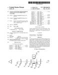
Schematic Representation of the SHS1
·._)
SECTION II
DRAWINGS AND DOCUMENTATION
~---
Drawings:
\
a.
b.
c.
d.
)
.--------------
The bidders must submit the following:
'i\<~~ift.j~~~~~
, llJ,.1 .t-~ (a rJ9 n~ et"'ms M:
IH\f51
'~;'-'
.. ..
i
A
___--
Mechanical drawings showing detailed physical specificatim1sJbr_Item.-No:--hfn~
No. 2. As specified in section .. ., Schedule of Requirements, Tablel -List of Good and
Schedule.
Mechanical drawings showing detailed physical specifications for all PV modules for
Item No. 1 and Item No. 2. As specified in section ... , Schedule of Requirements, Table
1-List of Goods and Schedule.
Mechanical drawings showing detailed physical specifications of the battery and
controller box.
A circuit diagram showing the wiring connections of sub-items assembled in the battery
box.
Documentation:
The PV systems must be provided with two supporting documents, namely, a User's Manual
intended for the customers (to be included with each of the packaged systems) and a
Technician's Manual for Installation, Operations and Maintenance (for use by the service
technicians). The latter will include the specific details on installation, operation and
maintenance. The documents must be provided in English with permission to translate into
local language. The User's Manual documentation should be simple and easy to understand.
Sketches and graphics should be provided to make the manual easy to understand and use. The
documentation shall include the following:
1.
2.
)
3.
4.
5.
6.
Theory of operation with a discussion on: battery charging by the anay; functions,
battery low voltage protection and battery overcharge protection. The relationship
between energy available on a daily basis and sunlight conditions should be clearly and
simply explained.
A description of all user interactive hardware including disconnect switches and status
indicators.
Procedures for proper system operation, including a list of load limitations and any
problem loads. Suggested operation, including load conservation during periods of
inclement weather and/or a low voltage disconnect event. The procedures for checking
that the photovoltaic array is not shaded and how to prevent shading must be expla'
. ·~
.
.
~ ft<:"Any user mamtenance Items.
~;
~{~
Procedures for emergency shut down and for extended periods of system non- ~::~ ~
-·
A trouble-shooting guide for users.
:!: '
·:~~~· • w
•*\
~~
~.
l
~
(1'\
""·
~ ·~.....,.
;;
f, 'W.
.
.'
~
~
4.- 0
~· -~
<>i ·~ .~ ~
~1CITE o'V Cw-v:
12 ~
C> ..
Technician,s Manual for Installation, Operations and Maintenance
1.
2.
3.
r
l-=------
•
o
•
•
•
'
•
•
I
/
4.
5.
6.
7.
8.
------
A complete list of all system sub-items, with associated .JllllllUf~!er~i~1S
specifications and warranties.
~··a\ie•~~~-i.j~~~ u~
Complete installation instructions.
\
N~f'\JC'\5\t1'1\'.n: '
A recommended post-installation acceptance test procedures, vncj.y~:U·trg,hl\~roptiafe
- -set points and test procedures. They will include the following:
Verify that the installation of the photovoltaic module with regard to position,
direction, inclination and shading avoidance will maximize energy generation.
Ensure that the battery has received an equalization charge just before installation.
Use a shunt to measure the current from the array under charging conditions to
verify the array charging current. This measurement should be done under clear
sky conditions.
Test all the loads for proper operation.
Make system-wide voltage drop measurements in the sub-circuits to verify that
connections arc within the maximum allowable voltage drop.
Note all measurements in the installation log.
Explain to the user the system operating principles, load management requirements,
impact of shading of the array and how to check and avoid it, user maintenance
checks and how to conduct them.
A recommended annual maintenance schedule, with complete maintenance instructions.
A detailed trouble-shooting guide referencing all the system sub-items. This shall
include repairs and diagnostic procedures that can be done by the supplier or a qualified
third party. Repairs and procedures not to be attempted by non-electricians and/or
electricians unfamiliar with photovoltaic systems shall also be identified.
A functional block diagram, electrical single-line drawing showing the placement of all
hardware and ratings of all sub-items and physical layout diagram.
Emergency shutdown procedures.
·
Product Service Manuals for the controllers, batteries, PV modules and lamps.
,)
13 ~-
SECTION III
INSPECTIONS AND TESTS
The following inspections and tests shall be performed:
I
\
General Condition
nfifr.'n,~'!'"ro~
•
nt-Jet~mH'.!'·
.
____
i
~-=----·---
1.
()
------------
..\---~·
··~:~~,~~
~~-;'l~•'JU
~
Sub-items rriust be tested and certified according to specified standards or
performance specifications at a testing center that is accredited to ISO 17025
requirements to perform such tests.
2. All sub-items, including spares, will undergo full bench testing at the supplier
factory or the originating source factory with proper documentation supplied. All
set point voltages will be verified and documented with the results dated and the
records maintained at the suppliers facility.
3. The supplier is to deliver random samples of the equipment taken from the
production line, for physical inspection and electricity performance tests by the
purchaser.
4. The purchaser reserves right to reject any Goods or any part thereof that fails to
pass any test and/or inspection or do not conform to the specifications. The
Supplier shall either rectify or replace such rejected Goods or parts thereof or make
alterations necessary to meet the specifications at no cost to the Purchaser, and shall
repeat the test and/or inspection, at no cost to the Purchaser
5. Each sub-item delivered should bear a pem1anent label with serial numbers plus
measured detailed electrical specifications as indicated in the Specifications.
~~~
~- ~ ::::::-"'
fi;;l ~
.. ,::s-
. .
l i Trammg
The bidder shall organize o training workshop in Cambodia on the use and
Home System (SHS) in consultation with Department of REF.
~z~ ·' -.~"'
teftlflr~
~~-- ~
( :} .z-.~fuf: .) ~
~ f"'\
til ·<:'~: ·J ?,)
I.':J
~~··~·~~ ..~· ( )
('., ~·)~"'""' ...-~· ,9
\
".fl/.., " •.,.
~~v
"~~
14 ~
c;
0
SECTION IV
INTERIM BATTERY ACCEPTANCE SHORT TEST PROCEDURE
Perform the test sequence as given below in Table 1 while maintaining the batteiy temperature between 20-25°C2 . The tests must be conducted
on 3 batteries that are randomly selected, at a testing center acceptable to the PMO. Record the data in Table 2. If the test results vary by more
than 10% of each other, for the three batteries, an additional two batteries should be tested to achieve better statistical significance. This test will
take approximately 17 days to perform using automatic battery testing equipment.
C apacity Test No.
Initial charge
Initial charge
1st discharge
Rest Period
1st recharge
1st recharge
2nd discharge
Rest Period
2nd recharge
2na recharge
3 ro discharge
Rest Period
3rd recharge
3rct recharge
I. C10 Test
2. C10 Test
\
Step
3. ClO Test
Table 1 Interim Battery Acceptance Short Test Procedure
C urrent/voltage
Current/voltage
End-of-step
Setting
Limit
Criteria
U=2.4 V/cell
+ Iro
2.4 V/cell
Duration 8 hours
+ Iro
U<l.8 V/cell
-Iro
OA
I hour
U=2.4 V/cell
+ Iro
2.4 V/cell
Duration 8 hours
+ I10
U< l.8 V/cell
-Iro
OA
I hour
U=2.4 V/cell
+ I10
Duration 8 hours
2.4 V/cell
+ Iro
U< l.8 V/cell
-110
I hour
OA
U=2.4 V/cell
+ Iro
Duration
8 hours
2.4 V/cell
+ Iro
I
I
Remarks
Constant current charging
Constant voltage charging.
I
Battery on open circuit
Constant current charging
Constant voltage charging.
Battery on open circuit
Constant current charging
Constant voltage charging
I
Battery on open circuit
Constant current charging
Cons~! voltage charging
Depending on the battery temperature (or ambient temperature in the laboratory during the tests) a correction of the capacity is necessary if the temperature deviates by more than 3 ~g-~
from 25°C. A correction factor of 0.6% per Kelvin is commonly used (see formula below). The formula can be applied for temperatures between 10 and 35°C. The pass criteria m~!?,~lle4'$ c;:for the temperature corrected values.
/'·?!~,.-~~"it
~~\"'"•
I
r... r.~~
2
~
25oC
CIO
=
C10TII'>6JSUmd
'r
1+ 0.006· (Tmeasured - 25°C)
~~~.:.e~~-'(:!~
"'<IWh.,"
~ t-<5
II
15
-.
II
l
..
H!lSHllF.tilBCUftntH\J'lmiM :
..
..
• ....
'
---:
1· r,:~
'' i .\
1.'_,... • =~
' ·
~~\ ~·,..l
~~~~I
(::-~S:'-~ \ r:>, ·""~··:...::*,) 0" ,~~-;
l~ -
I :f...
1'
~~ • •
0~
'. ;"',. _, ·<-.
. . . . .-..;~--. . ,.~.....·,
'"'"'' "£•; .
t
.._·
(\..~
<"'' "(..,, l'f ·::.!/..s~·
/
Dl l c.i'~ .•.i '
,...:..:..__.,.
......
~
u
/' ......
•\
Table 1 Interim Battery Acceptance Short Test Procedure
Current/voltage
Current/voltage
End-of-step
Remarks
Setting
Limit
Criteria
I 4. ClO Test
4th discharge
-Ito
U<1.8 V /cell
4th recharge
+ IlO
U=2.4 V/cell
Constant current charging
4th recharge
2.4 V/cell
Gradient of current Constant voltage charging
+Ito
is 0 A/s, but
maximum 36 hours 3
Alternative for lh recharf{e dependinf{ on availability ofequipment
i
lh recharge
+ 110
U=2.4 Vlcell
Constant current charging
lh recharge
2.4 V/cell
+ 110
I< 0.1 x lw
Constant voltaf{e charf{inf{
4fh recharge
Capacity charged in 41h recharge > 112% ofcapacity
0.1 x ho
discharged during 4th discharge
..
stn discharge
5. Cto Test
-!10
U<1.8 V /cell
Rest Period
OA
I hour
Battery on open circuit
5th recharge
U=2.4 V/cell
Constant current charging
+ !10
stn recharge
Duration 8 hours
Constant voltage charging
2.4 V/cell
+ !10
U< 1.8 V/cell
6. C2o discharge
-0.5 X IlO
Rest Period
OA
I hour
Battery on open circuit
Constant current charging
6th recharge
U=2.4 V/cell
+IJO
Constant voltage charging
6m recharge
Duration 8 hours
+ I10
2.4 V/cell
U< 1.8 V/cell
7. C 100 discharge
-0.1 X Ito
Battery on open circuit
OA
I hour
Rest Period
7th recharge
Constant current charging
U=2.4 V/cell
+Ito
Constant voltage charging
7tn recharge
Duration 8 hours
2.4 V/cell
+I!O
U<
1.8
V
/cell
8. Cs discharge
-2 X Ito
Battery on open circuit
I hour
OA
Rest Period
Constant current charging
gtn recharge
U=2.4
V
/cell
+I10
Capacity Test No.
\,
v
Step
I
./~r::.
;( c-) .x..
~
~ ','
~~tnyr.Ql;;;-:\~.Z'->
3
Note that the end of the constant voltage charging is reached only when the battery current has not changed for two hours. If this criterion has not been reached after 36 hours of
process, continue with the next step of the test procedure.
f /,.. 1
r
16
/
I
··-·
..__
y .. >:1
..
..
., ...
----·-------
'tB~-z.~·
),
h!~;mt:tH1tnsruoruutnaun,...
11
1::..~~~
*
t..\
0~~- - 1 ~u
\ ·,.- ·~t~·- ~:,v:~-'.?.:J~
\.,
~""·
('\. x: , ""
·-; .. . .! o"""
<~\
..,.,
ia~-~l'!ii~1~~~fi~
.,~
I
t . .:.~ r
,,.
.r~ ~ ·/.~'<'
··'~'(f-; --c.~~-
~c
OU
I' .,
\
;
.,__,
'-..../
Capacity Test No.
6. C10 Test
I
Discharge
Capacity Test
1. C10 Test
2. Cw Test
3. clO Test
4. Cw Test
5. C 10 Test
C2o Test
C 100 Test
Cs Test
6. clO Test
\
Step
8th recharge
9th discharge
Rest Period
9th recharge
9m recharge
Table 1 Interim Battery Acceptance Short Test Procedure
Current/voltage
Current/voltage
End-of-step
Setting
Limit
Criteria
2.4 V/cell
Duration 8 hours
+110
U< 1.8 V/cell
- 110
OA
1 hour
U=2.4
V /cell
+ 110
Duration 8 hours
2.4 V/cell
+110
Remarks
Constant voltage charging
I
Battery on open circuit
Constant current charging
Constant voltage charging
Table 2 Data Recording for Interim Battery Acceptance Short Test
Discharging
End-ofBattery
Measured
Pass Criteria
Current (A)
Discharge
Temperature
Capacity
Voltage
(°C)
(Corrected to
(V/cell)
25°C (Ah))
1 x l10 =
1.80
1 x l10 =
1.80
1 X IIO =
1.80
'
1 x l10 =
1.80
1 x 110 =
1.80
Measure Capacity> 100% Nominal Capacity
0.5 x I10 =
1.80
0.1 x l10 =
1.80
~
~ ! ~~<t>60L'.
1.70
2 x l10 =
1 X IIO
1.80
Measured Capacity > 95% Nominal ~~.k 1,
.
&
¥
J ..t;;
f&of&of&o ~ o(j.o(ff.o<f.,
I
~
...
17
I
L
-
~r.n~i\1~~~§
J
Htl81£1JM~SCU9MHMt!'UClfi ·
til;
•
-
,..
1
,_...*-'~~---·-
.~
r"'"~:1
.
.....--.-............- ...._i
l~~l~·."' \ iu•..:"; '. ~;\;; ·i·~~ ;;
..._.
II
..
: unR1 tun tn an' 9 "~ ~n £!1 wn :
N
I
'
•
2015
e
.........Y.\,...__.,...,.,...,.....__ ...,_..,..____
Technical Specifications
For5Wp
Solar Home Systems
in the Kingdom of Cambodia
~- )
•
1
i
'
'.'
PREAMBLE
The objectives of the Royal Government of Cambodia (ROC) are that by the year 2020, all
the villages of The Kingdom will have electricity of some form and by the year 2030, at least
70% of households will have access to grid-quality electricity.
R:;;
G:.;:C~-
To assist in development of electric power in rural areas of the Kingdom of Cambodia, :.:
has established a fund, by the Royal Decree No. NS/RKT/120~--4ttr1:JeCiffiber .
2004, called "Rural Electrification Fund" (REF).
.\ " " ~ "~~i: ief•.\W..,
iS:"'
Then on August 22,2012 ROC has issued a new Royal Decree No1,N~~1{!¥l~.i:f9d~\i~1'\l!\'M:
some articles amendment of the old Royal Decree to Put REF ~ncf~r the mahagemen,Lu£-- -·Electricite du Cambodge (EDC). Its activities are:
--------=--
To promote equitable rural electrification coverage by facilitating the Population's
access to electricity at affordable price for economic, social and Households uses,
thus contributing to its poverty reduction; and
To promote and encourage the private sector to participate in providing Sustainable
rural electrification services, in particular for the exploitation of the Economic
application of well proven, technically and commercially, of new and Renewable
energy technologies (RET).
In order to promote the supply of electricity from solar energy and to manage the Technical
aspects of Photo-voltaic modules and other 5Wp Solar Home Systems (SHS) Equipment, the
Teclmical Specifications for 5Wp SHS are established.
, . -;.Q.
The Technical Specifications will be revised and updated by the
at!&.e ~... ~ , al
Electrification Fund during the implementation period of the Proj ect a
products emerge.
~~:::
\) 11
,..., ( ~q ~~~~'1·
·~(~s ..__
•r...
~,,¥' t~~~\d
'I};
. ,. .
?,
n...-' ,·\'.;.,
·:. ·~·.
~\))·:·~
,, ... ~.
·~ .">;
'-::. t DU
r ,, ~~,,
.
"··"'
,.,\~
' i'J':: ......:.:__~ 0"
~
'
I
,l..IJ
.p_ ~
i' "'·\
-·--....... ,
,.J'
..·
.. '.
SECTION I
TECHNICAL SPECIFICATIONS PICO SOLAR HOME SYSTEMS (PSHS)
1.
General
A Pico Solar Home System (PSHS) which is included the Portable Solar Lamp (PSL) is
defined as a small PV-system with a power output of 1 to lOW, mainly _used ~or lightin~ .
Portable lantern, Phone charger and thus able to replace unhealthy and me~ces
\
r:__---- ~:.f.·V~•«J"!:~
·\
such as kerosene lA.mps and candles.
~
Nominal system voltage (rated voltage) shall be 3.7 Vdc.
\
"
~~&~A••~ ~n
1 t -. m !\l~~
.. ~l-1-;..l'
\
·~
•n.,~f\\JC\..~tntM: \
·•
'*
------
Depending on the model, small ICT applications (e.g. mobile phone cl}_arget:,-Fadto}can also
be added. 5Wp SHS are powered by a small solar panel and use a battery which can be
integrated in the lamp itself.
2.
Advantages of PSHS
5Wp SHS offer a wide range of advantages:
•
•
3.
There is no need for installation by a qualified technician. 5Wp SHS is a fully
integrated system that is designed for set up and use by the Customer ( 11 plug and
play 11 systems).
Little maintenance required high degree of expandability and flexible use.
The prices are general. It is within the payment capacity of most rural people in
developing Countries.
Applications
5Wp SHS offer a variety of using purposes:
(-)
2
---'
SECTION II
GENERAL REQUIREMENTS
1.
Applicable Standards
All goods and equipment supplied under these specifications shall conform to the following
standards unless otherwise specified. Other national or manufacturers' St~~\
accepted under the condition that they ensure substantial equivalenc~ot higher. ~ifi"~'5~~~ ·~
,
I
tti1(tt •
:.,) ~
\1
•
\
Internat~onal Electro-technic~! Comn:ittee. (lEC) 61215: \ 993•. Cri~Vt\lffit fu\¢thl N'\ tn! C\!1 · .
Terrestnal PV Modules - Destgn Quahficat10n and Type Appr~P •·· "'
_ _ _ _J
IEC 61646: 1996 Thin Film Silicon Terrestrial PV Modules - D.~sign-QtlaliftCafion
find Type Approval.
IEC 60904-1: 1987 Photovoltaic Devices Part 1 - Measurement of PV Cun·entVoltage Characteristics.
IEC Standard 61427 © IEC: 2001 Ed.2, Secondary Cells and Batteries for Solar
Photovoltaic Energy Systems - General Requirements and Methods of Test.
PV GAP Recommended Standards (various) See "Standards and Blank Detailed
Specifications in ht,tp://www.pvgap.org for updated list.
ASTM International E standards (E 900-2000).
Acceptable standards for common electrical sub-items (House kit) are DIN, JIS, BS
and TIS or IS09000 series.
2.
<.J
Certification Requirements
Products to be financed under the Project must have test certificate from a testing
and certification organization acceptable to the Government stating that the SWp
SHS meets or exceeds the specifications cited in this document. Organizations
accredited according to ISO 1702S or equivalent standards will be acceptable for
issuing the component certification.
Products that bear the Photovoltaic Global Approval Program (PV GAP) Mark or
Seal or certified according to PVRS requirements will be acceptable for use in the
Project. PV GAP is a Geneva, Switzerland-based, not-for-profit international
organization, dedicated to the sustained growth of global PV markets to meet
energy needs worldwide in an environmentally sound manner. For more
information see http://www.pvgap.org/.
For sub-items not bearing the PVGAP Mark or Seal, the goods or equipment to be
supplied must have a type-test certificate from an accredited testing and
certification organization stating that the PV System sub-item meets or exceeds the
specifications. Organizations accredited according to ISOJ 7025:2005 (General
requirements for the competence of testing and calibration laboratories, and have
those specific standards within their scope of accreditation), or equivalent
standards will be acceptable for issuing the sub-item certifications.
For sub-items made using same (i) production processes and construction methods,
(ii) materials and (iii) quality control procedures as the certified sub-items, but are
of different sizes/capacities, a Manufacturers Self Compliance Certificate if
accompanied by the Certificate of the tested sub-item will be acceptable. The
Manufacturers Self Compliance Certificate must be signed by an ..Dfti.~;..of the
manufacturing company and attest the following: "We confir~ ~f~zg~x~
~:-s bitem(s) listed below have the same design and operating pr~#~es ~'e.. W
ma~e and model number] of xxxxx sub-item that has a certifi ~/ac~. ~· .. e t W
proJect, or bears a PVGAP Mark or Seal. We further confirm ~\~e
. ~~
-~~\~.;!.
l~ tJ~-1t.(6ff
- '~>. w ..·~ ,., 1:$··'
3 ~
-;,):....:...;:::;...· ,:$}
I~ r'!J'f/i..;~
INJ
, 12
__!..;/
items use the same (i) production processes and construction methods, (ii) materials
and (iii) quality control procedures as the certified sub-items. lList makes and
model number ofxxxxx Sub-items.]"
All components, systems, documentation, and installations as appropriate, shall
.. ...
... · . <··
meet all the requirements given in this document.
\- 3.
Operating Environment
I
-
~-~~ii~\~\)1~~
'"'\«"'W"nmH\D:
H1'Hr,'I~1!M~~ ... ; . .... ·-
i'
The entire system shall be designed and built to withstand ~the envi..r~---·
conditions found in Cambodia. For design purposes, consicter-tfiattemperature
extremes could range from + 10 to +40 degrees Centigrade and humidity levels
could reach 90 percent.
All wiring, closures, and fixtures must be resistant to high humidity conditions,
corrosion and insect and dust intrusion. In particular, electronic components and
circuitry used in coastal areas subject to humid and salty conditions should have
protective coatings to resist corrosion.
--;
4.
Warranty
The supplier/dealer will provide a minimum twelve-month warranty against manufacturer's
defects on all parts of the PV systems. The warranty period twelve-month to the user will start
from the date of installation agreement between user and EDC/REF. The supplier will deal the
warranty work until finish warranty period ofthe contract.
The specific warranty conditions are further Defined in Specifications A to G. The supplier/
dealer will be responsible for round trip Transportation charges of replacements for all parts
of the PV systems (Item No.1 to Item No.2) and balance of system sub-items (Item No ... to
Item No ... ) from and to destination places as specified in the Bidding Documents (BOs).
The Supplier warrants that all the Goods are new, unused, and of the most recent or current
models, and that they incorporate all recent improvements in design and materials, unless
provided otherwise in the Contract.
.)
On all major individual components, manufacturer's wan·anties will be passed through to the
user. Specifically, the PV modules should be warranted against reduction of output of no
more than 10 percent of rated capacity over a minimum ten year period. The chargecontroller,
low voltage disconnect, switches, and charge indicators should be warrantedfor at least one
year. The battery should be warranted for at least two years. Battery end-of-life will be
determined when the battery capacity down 1.75 V/cell at 25 degreescentigrade drops to less
than 80 percent of the initial rated capacity.
5.
Packaging and Transportation
The following instructions on packaging and transportation apply for each item before
shipping to final destination in CamLv~~a, ~u~ ~a.:>... .~ ,m the quantities indicated in list of good
and delivery schedule.
6.
The bidder must keep in mind that most of goods have to be shipped to their
ruraldestination on roads/tracks, which are in poor conditions. Packing box labels,
sizesand weights should be appropriate for manual handling in rural areas by no
morethan t\;vo persons per item.
A Packing List shall be attached to the outside of each box so as to be clearly
_
-------readable and accessible for scanning with a bar code reader.
1 -.. ,, ~~~~\:S~tl
Product Components
\
~~-~1Q ~.>
"'
.
ruin\JC\f\tlls~n·
,
The products should be composed with PSHS together with PSL to
time and should consist of the following components.
)
5~
~e ~pjff1J~ ~t~~ s~__....
.--
-----
SECTION III
DETAIL TECHINICAL SPECIFICATIONS OF PSHS
AND ITS COMPONENT (PSL)
1.
Specification A: Solar Photovoltaic Modules.
,....-
•
·:S::.~
.,~~~·Q,I'
~ ll••~i·\;u
1
..
-------------\
:.. ,. .....
·,
---
"
1
\
The Module should be 5W/ 6V Poly-Crystalline solar parlel.
• _ ~n 1ti'\Hf'5't!\1~: \
The efficiency of the solar panel should be over 17%.
. ·: " •:·'''~'"!' · • "' _ ____-J
The photovoltaic array will consist of one or more flat-plate photovo~ed~
Cells should be laminated between high transmissivity low irontempered glass and
weather resistant back-sheet to protect moisture penetration.
The photovoltaic module should have a peak power output of at least the specified
rated value respectively under Standard Test Conditions (STC) as defined in
IEC0904-1 . The peak power output for thin film modules should be the value after
light soaking.
PV modules that bear the PV GAP Mark as proof of compliance with PVRS2 or
PVRS3 will be accepted. In the absence of a PV Mark or Seal, modules must be
certified in accordance with IEC 61215, IEC 61646 or lEE Specification 1262-1995
and must be manufactured in an ISO 9000 accredited manufacturing facility.
The modules must be constructed with heavy duty anodized aluminum frames
tough enough to protect the modules from damage during use and during transport
over rough terrain, and suitable for drilling and bolting for support brackets.
- _)
Warranty: The modules should be warranted against reduction of output of no more than
10% of rated capacity over a ten-year period.
2.
Specification B: Battery
2.1
Battery in System Unit of 5Wp SHS
The battery should be installed compactly in the system unit.
The battery type should be Lithium (Li-ion) or Nickel Metal Halide battery type.
Lead Acid battery should not be used to avoid the increasing of size and weight
which lead to the inconvenience of portability.
The battery voltage and current at CIO should be 3.7V, 6600mAh (25.9 Watts,
I 00% efficiency use).
The Span Life should be at least 500 Circles.
~)
Warranty: The System Unit must be warranted against failure for a minimum of2 years.
2.2
Battery in Lamp Unit of PSL
-
The battery should be installed compactly in the lamp unit.
The battery type should be Li-ion battery type. Lead Acid battery should not be
used to avoid the increasing of size and weight which lead to the inconvenience of
portability.
The battery voltage and current at ClO should be 3.7V, 2200mAh (8.14 Watts,
100% efficiency use).
• ~~
The Span Life should be at least 500 Circles.
z:-};. ,... ,
,.<~,
.,,..,
'
....,.,
' f'
"'~ ,.,
:\\;.1'
~5:
'"'l
Warranty: The Lamp Unit must be waiTanted against failure for a minim r_) ~~t~'-~.
.
~~
\ ... \'\... ~}'.-'··
J,, .
""""
. ·.· ~ \ ·'I· " ; ....~l1J :> •
\ ~·,,
~'\
~ ~
,'\(,, . -~
\•
6
\
"
....
..
1
A, . ,_ ._,:
1
.
-~·'
'~ ...........
.Ju_
c~l\"~
//
(-
•
(·
.i; • • ... ,.~ t'"\V I
(JV I
.
H
..:.---
3.
Specification C: Lighting Source
3.1
Lighting Source of SWp SHS
The light source should be 2W LED Lamp which is installed with its lamp socket.
One output cable with 2000mm of length should be already connected to the lamp
socket at one side while the other side should be connected with DC male connector.
The cable's size should be big enough to prevent the power loss.
_
The connector must be fit to the female connector located at the ou~
the system unit.
·- - - ~iall~~\S~!)
The lamp should be adjustable for its brightness.
\
~ H'\!':
The brightness level of the lamp should be adjustable into 'Amog.e~'fYlWd\WMitm! N"t!'
which are switchable at 4 locations :
\ '4 ,;, •.\ '· · ' ""
- ----- _.._-·a) Stage I : I 00% Brightness.
b) Stage 2: 70% Brightness.
c) Stage 3: 30% Brightness.
d) Stage 4: 0% Brightness (Turn Off).
u,...
---
.
---
The lamp should be super bright white LED light with 6000K to 6500K and I60200LM.
The lamp should be aluminum alloy case.
The life time of the lamp should be over 50,000 Hours.
Warranty: The lamps must be warranted against failure for a minimum of2 years.
3.3
Lighting Source of PSL
The light source of Lamp Unit should be I W with 16 pes of cell of LED which is
installed with the body of the lamp unit.
The lamp should be super bright white LED light with 6000K to 6500K and
IOOLM.
The brightness level of the lamp should be adjustable into 2 stages with a switch
which are switchable at 2 locations:
a) Stage I: I 00% Brightness (Tum On).
b) Stage 2: 0% Brightness (Tum Off).
The Lamp Unit (body) and its handle should be ABS materiel or materielequivalent.
The globe holder of the lamp body should be transparent PC or materielequivalent.
The life time of the lamp should be over 50,000 Hours.
4.
Specification D: Input and Output
4.1
Input and Output of SWp SHS's System Unit
4.1.1 Input
,,•
.
The input connector located at the system unit should be connectable with solar
module for charging.
The input connector located at the system unit should be connectable with AC
adaptor for charging.
The input connector located at the system unit should be connectable with personal
computer (USB) for charging.
The AC adaptor should be provided to charge the battery of the system with 230V_______..
electricity.
__.----:-::-___.\
-
4.1.2 Output
\
~tf.e~~\f~~;a
fi1
~1f\~:
"f\"' r.P' a:r. 8 ru ~" ~ (\f\
.
USB female connector or other type of female DC connector rs-.a't!Cepta151e at ~---of the system unit.
-~- --·---The output voltage should be 5V.
The output current should be at lease 700mA which is enough for charging mobile
product such as phone, digital camera, MP3 player... etc.
The number of the output connectors located at the system unit with the same rate
should be at least 4 outputs: 2 outputs for lamp and 2 outputs for multi-purposed
usage.
4.2 · Input and Output of PSL's Lamp Unit
4.2.1 Input
The input connector located at the Lamp Unit should be connectable with solar
module for charging.
The input connector located at the Lamp Unit should be connectable with AC
adaptor for charging.
The input connector located at the Lamp Unit should be connectable with personal
computer (USB) for charging.
The AC adaptor should be provided to charge the battery of the system with 230V
electricity.
.)
4.2.2 Output
USB female connector or other type of female DC connector is acceptable at output
of the lamp unit.
The output voltage should be 5V.
The output current should be at lease 700mA which is enough for charging mobile
product such as phone, digital camera, MP3 player ..• etc.
5.
Specification E: Safety Protection
The system of both 5Wp SHS and PSL must have the following protection installed together
to prevent the damage of the whole system and human life.
The protection of Over Charging.
~
The protection of Over Discharging.
~ t~~~
The protection of Short Circuit.
_,"f' ,/ ~~:A i~~\
The protection of decomposing by the~
r.: ~~ .... }~~ \
(;i,
]ti_
.\ . r;~.\-:. ·j
·
.
-:.."'f
...i;Fp • • I
·~ ~"' .. ,(,,
....._,
·~
/("
\
8
...~
~~c.
••
.:,;
-~...
rt~
{'..'.:>
'·'/,c- ... •• . '0'~
' · ' D(J (.f!.~Q)
~-·-
ty'
,,,
.
. .•.
6.
Specification F: Charging Time
The fully charging time is varied according the condition of charging such as the weather
(sun!igh1, cloudy or raining ...) and the placement of the solar panel. However, the charging
time of the system should not be exceeded the foll owing period at normal condition.
6.1
SWp SHS Battery
Charge by Solar Panel: 5-8 Hours
Charge by Personal Computer: 8-10 Hours
Charge by AC Transformer : 5-8 Hours
6.2
PSL Battery
Charge by Solar Panel: 3-5 Hours
Charge by Personal Computer: 3-5 Hours
Charge by AC Transformer : 3-5 Hours
7.
Specification G: Working Time
The working time is varied according the condition of using. However, the working time of
the system should not be less than the following time period when calculating base on the
number of lamp.
7.1
For SWp SHS
13Hrs 100% lighting.
20Hrs 70% lighting.
43Hrs 30% lighting.
The working hours will decrease according to the number of lamps.
7.2
)
For PSL
The working time is varied according the condition of using. However, the working time of
the system should not be less than 8 operating hours.
8.
Specification H: System Accessories
The accessories of the Pico Home Solar System included Portable Solar Lamp should be
included the following items.
1 pes of 5 Watts solar panel with the specification A.
1 unit of 5Wp SHS with specification B and D to K.
2 pes of lighting source with the specification C.
1 set of charging accessories (adaptor for phone and mobile electronic devices).
1 unit of Portable Solar Lamp with specification B to K.
9.
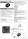
Specification I: Block Diagramof Each Unit
The System Unit of 5Wp SHS and the Lamp Unit ofPHL should
as in Figure 1 and Figure 2 respectively.
9
~
/~ -~
!.v".:; / 1~,"-~~·
cofllj¥~"eJ~t~g~~·~
I ~~ \ '-:::. ···~
,M~>
~
·\.
-P \ \ ·:--'
*
'V,~.J . ··v
-v·
·(~ .....:~;,~ ~~ ~/ ~')
..
~~
.I:(.....
'ii'
"/·.. -........:.....::......-- \.)
am
Ill
.L/
~ .
Over Charge Protection
Charge
Controller
Over Discharge
Short Circuit Protection
Dim ModeController
Battery
Mode Selection Switch
Fig 1: Block Diagram of System Unit of
Charge
Controller
Over Charge Protection
Over Discharge
Short Circuit Protection
Battery
ON/OFF Switch
Fie 2: Blocl<. Diaeram of Lamp Unit ofPSL
10.
Specification J: Packing Detail
The package of both 5Wp SHS and PSLshould be packaged as a gift box which all the
accessories in Specification Hare included.
11. Specification K : Certification of Whole System
,t: . ~"~
~~--- -<'.:.
':7
.\
The whole system of both 5Wp SHS and PSL should get the compliance ve(.§~~1~
the following certificate to proof the quality of the product.
~ (;~~~~·~· \ ~
("I,. ~~ ·,~l.
.._
J'f•
-:.~'.:_,.,~:~,Ji~*-.:
t.,~· (')~-.
,. ~
~·
CE Certificate.
ROHS Certificate.
FCC Certificate.
'?~
......
• ..., ~· .
~
"'~~
10
~
l.
Supply Requirements
\
List of G oods and Delivery Schedule
For 50Wp Solar Home Systems
(SHS)
r
I:
f
~
..
-
~•t:er!l~t:SlfS:>
~
tltfB1l1Jl't~8flJ~M~H\J'l011U!:
___________i
,
Page 1 of5
r·u v,...
.
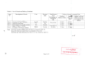
Table 1: List of Goods and Delivery Schedule
Item
NO
Description of Goods
Item 1
Item2
Item 3
Nominal 50 Wp PV System
House Kit Sub-items
Spare Battery for 50 Wp systems
Spare 12Vdc x 7 W CFL
(Compact Fluorescent Lamps)
Item4
Unit
10,500
1
500
10,000
Physical
unit
Nwnber
Set
Nwnber
Final (Project
Sites)
Destinations as
specified in
BDS
Phnom Penh
Responsible by
Nwnber ,
the Bidder
Delivery (as per Incoterms) Date
Earliest
Delivery Date
Latest
Delivery
Date
30 days
30 days
30 days
60 days
60 days
60 days
30 days
60 days
Bidder's offered
Delivery date [to
be provided by the
bidder]
I
Note: Sub-items needed per PV system for Item 1 is shown in Table IA.
House Kit Sub-items under Item 2 are detailed in Table lB.
Quantities per final destination for Items 1 to 2 are detailed in Table 1C.
\
p-~
rUAir.mntn&n.HJftlltu~I\IOi,
.:.~.o~ ~~\G~ts~;s
...
I
\t
Page 2 of5
I
....
11'.
......
•
-..__
<#
...
--
Table lA: Breakdown of sub-items required for each Solar PV system
Each system comprises the following sub-items
Number of module per system
Module size range
12Vde battery charge controller
12Vdc battery charge controller
12Vdc battery rating (20h rate)
Number of batteries per system
Battery Boxes (self-standing per wall mounted)
12Vdc x 7W CFL (input power rating) with holder, reflector and
insulation ring
Plug and socket for module inlet cable 4mm2
Plug and socket for load outlet cable 2.5mm2
Load outlet cable to lamp 1mm2
Circuit breaker for load outlet
-~<
Quantity/Size
Item 1
Specifications and standards
Number
Wp
Number
Current rate
Ahper Wp
Number
Number
1
50-55
1
5
1.4 to 1.8
1
1
Specification A
Specification B
Specification B
Specification C
Specification F
Number
2
Specification D
i
Set
Set
Set
Number
1
1
1
1 (5A)
Specification ElF
Specification ElF
Specification ElF
Specification F
~r
r
~•~en,~~$-5~~:5
.... "'
u
tz-
I u~a1mne:2m!ngfl~aun:
Page 3 of5
·--
---- ·-------- -----··-
-~
I
i
j
I
Table lB: House kits sub-items
Item 2 - House kit comprises the following sub-items
2
PV module inlet cable 4mm stranded and flexible insulated copper, twin
core sheathed and insulated (12m per system)
2
Load outlet cable 2.5IIL."Tl stranded and flexible insulated copper, twin core
sheathed and insulated (3m per system)
2
Load outlet cable to lamp 1mm stranded and flexible insulated copper, twin
core sheathed and insulated (12m per system)
15A tumbler switches
Pin sockets and plugs
Supporting box for sockets and plugs
Wood screws 05mm x L50mm to fix the board on the wall (I)
Cable clips N4 (for 2x4mm2 )
Cable clips Nl (for 2x2.5mm2)
Cable clips Nl (for 2xlmm2)
Wire nails 1Omm length
Bracket nails 80mm length
2
Strip connector 4mm
Insulation tape rolls 1em width x 5m length
Bolts 06mm x L20mm <2)
\,
Note:
Unit
Quantity
Specifications and standards
meter
126,000
Specification E
meter
31,500
Specification E
meter
126,000
Specification E
Number
Number
Number
Number
kg
kg
kg
21,000
21,000
10,500
52,500
210
84
336
Specification E
Specification E
Specification E
Specification E
Specification E
Specification E
Specification E
kg
210
Specification E
kg
Strips of 12
roll
Number
500
1,050
1,050
52,500
Specification A
Specification E
Specification E
Specification A
I
~,:-
( 1) including 4 per board + 1 spare
(2) including 4 per panel+ 1 spare
r--
/
~
Page 4 of5
- - - -·- ·--- ·- .. -
{>1461in.l~~l!;':li
-----------------·
· rntiflf.fJn
tnaru9nunnuun:
~
.,. ...
Table lC: Quantity per fmal destination for Items 1 to 2
Item
Item 1
Item 2
\
Note:
Number
Number of systems and sub-items per fmal
destination (I)
10,500
meter
meter
meter
Number
Number
Number
Numberl.lJ
kg
kg
kg
kg
kg
x12 pc
rolls
NurnberlJJ
126,000
31,500
126,000
21,000
21,000
10,500
52,500
210
84
336
210
500
1,050
1,050
52,500
Description of Goods
Nominal 50WpPV System
House kits sub-items and spares:
PV module inlet cable 4mm.l
Load outlet cable 2.5mm.l
Load outlet cable to lamp 1mm2
15A tumbler switches
3 Pin sockets and plugs
supporting box for sockets and plugs
Wood screws
4mm.l cable clips N4
2.5mm.l cable clips N1
1mm.l cable clips N1
Wire nails 1Omm length
Bracket nails 80mm length
Strip connector 4mm.l
Insulation tape rolls
Bolts+ nuts
Unit
(1) Quantities per province may be subject to minor changes. Definite numbers to be confirmed during negotiation.
(2) Including 4 per board + 1 spare
(3) Including 4 per panel+ 1 spare
r ,
~
Page 5 of5
~-
:z::::::.,.~··-
::a::
•
!
;
yrY::
Cl:~
~~;u.;.:~!t-{\S~Z
•
t::
-
l~~lllngJB~U~n!!~~f
Supply Requirements
List of Goods and Delivery Schedule
For 5Wp Solar Home System
\
-··~------A
:l
.i
Page 1 of3
..
• •
---~
"
;
HfH!l~t~ ·:eru~ntHtJHfllUil:
.
L ___
~
•
~~n~efiJ~~\;S~~
~
-
~
~
--
}bt~
·'
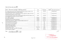
Table 1: List of Goods and Delivery Schedule
Item
No
Description of Goods
Item 1 Nominal 5Wp PV System
Unit
Physical
unit
Final (Project
Sites)
Destinations as
specified in BDS
2,000
Numbers
Phnom Penh
Delivery (as per Incoterms) Date
Earliest
Latest
Bidder's offered Delivery
Delivery Date Delivery Date date [to be provided by the
bidder]
30 days
60 days
Note: Sub-items needed per PV system for Item 1 is shown in Table lA.
Quantities per fmal destination for Items 1 are detailed in Table lB.
Table 1A: Breakdown of sub-items required for each Solar PV system
Each system comprises the following sub-items
Quantity/Size
Item 1
I
Specifications and standards
i
I
'
Module size range
\
i
Wp
5
Specification A
Solar Photovoltaic module and input cable 4m
Number
1
Specification A
"Plug-and-Play" system unit (Battery, Charge Controller,
Protection Circuit. .. etc)
Number
1
Specification B and D to K (All in one)
Lighting Source (Cable 2m, LED Lamp 2W, Plug .. .etc)
Number
2
Specification C (All in one)
Portable Solar Lamp
Charging accessories (adaptor for phone and mobile electronic
devices)
Kit for wall mounting of the System Unit of 5Wp SHS
Number
1
specification B to K (All in one)
Number
1
Number
1
I
I
...........
. .#1
\~
ur. suun rn fHUt ru1 M muut: I
A
Page 2 of3
117
,_._
------··-··I
Table lB: Quantity per final destination for Items 1
Unit
Number of systems and sub-items
per final destination (I)
Solar Photovoltaic module and input cable 4m
Number
2,000
"Plug-and-Play" system unit (Battery, Charge Controller, Protection
Circuit ... etc.)
Number
2,000
Lighting Source (Cable 2m, LED Lamp 2W, Plug ... etc.)
Number
4,000
Portable Solar Lamp
Number
2,000
Charging accessories (adaptor for phone and mobile electronic devices)
Number
2,000
Kit for wall mounting ofthe System Unit of 5Wp SHS
Number
2,000
Item
Description of Goods
Item 1
-
Note:
- ----
(1) Quantities per province may be subject to minor changes. Definite numbers to be confirmed during negotiation.
rr
\.
-~
....... ;:.;;.:-:(<:·~-~ -·l."--.:::
~ ............ ~~ l ,,.fot:~,~4V
... !.,~>
. .
'"'~
I. H tHn
,. ttf n "tt 'l nHf n ~H\~
... 01 H\W
L ---- - - -
~
Page 3 of3
Technical Characteristics of SHS-SOWp
Items
I
Description
Unit
Statement of Compliance
of Bidder
Remarks
Solar Photovoltaic Module(s)
Country of Origin
Any country
Model number
Type (a-Si, Mono/Poly Crystalline Si,etc.)
Min Number of cells in series per module
Number
Open circuit voltage (Voc)
v
Short circuit current (lsc)
A
Rated peak power (Pmax) at Standard
Testing Condition
\
EDC's
requirement
Any country
Poly- or MonoCrystalline
36
I
I
Wp
Vmax
v
I max
A
'
NOCT (Nominal Operating CellTemperature)
DegC
Anodised Aluminium Frames
Yes
JUNCTION Box: Weatherproof,suitable
Cable entry inlets I outlets, external
Grounding screw, + ve and -ve terminal Mark,
ULAE Certification.
Yes
~--
~
Page 1 of6
-
-------
I
I
......
-
~na~~~if\5~~
L~~-run~eru~nyc..omJnfl:
]JJY:
Test laboratory
-
Attach I-V Curve
Yes
Test Certificate provided
Yes
Warrantee against reduction of output
Of no more than 10%
I
PVGap,IEC
61215,61646
Test certification standard
Year
I
!
i
10
Support Structure
Type
Wind velocity %--Withstand Capacity
I
I
(Roof/Pole)
m/sec
35
Material
II
I
Charge Controllers (12V)
Country of Origin
Any country
VRLA&AGM
(for dry battery)
Model number
\
I
Enclosure material
Rated voltage
Nominal Current for 50Wp
Vdc
12
A
5
Reconnect voltage (Vrr)
I
Yes
High voltage disconnect
Voltage regulation set point (Vr)
!
v
v
Charging indicator
. Battery Status OK
(Yes/No)
Yes
- --
Page 2 of6
\rs
;
...
mao211Jlf~~~
I H~mttH1~8n.t!ng~nunn:
L_ ____
lfW~"
I
--~ '
. System Charging OK
(Yes/No)
. System Connectiong Status OK
(Yes/No)
Maximum Current Handling Capacity
A
Disconnecte Voltage
v
v
Reconnect voltage
Yes
Current draw with LEDs
rnA
Current draw without LEDs
rnA
10
Short circuit protection
(Yes/No)
Yes
Reverse polarity protection
(Yes/No)
Yes
Electronic over current protection
(Yes/No)
Yes
Lightening surge protection
(Yes/No)
Certifying body
PVGAP/PVRS6
Test certificate provided
Warrantee
!
Yes
Year
2
(Yes/No)
Yes
System Monitoring
\
Battery State-of-Charge indicator
Type of indicator
Indicator settings
Fully charged suitable to use
Energy conservation
v
v
Other (explain)
-·
~
..
b"1~~fliijg'i\SlfiZ
Page 3 of6
.
~
I
unrnurntnsnntnuMmznr!:
....
., ...
l_
- ·· -·- ·-
i
-
l' J I"'
I
m
Battery
Country of Origin
Any country
Model number
Battery enclosure
Open/sealed
Battery type: Valve regulated Lead Acid
(VRLA) and Absorbed Glass Mat (AGM)
With flat or tubular plate
Sealed
VRLA&
AGM
!
Nominal voltage
v
12
Capacity per battery at C/20 down to 1.75/cell,
50Wp
Ah
50
At (DOD) of 10%
No
1,000
At (DOD) of 50%
No
200
(%/month)
5
12
Battery Gassing Voltage
v
v
Max. Charging Current (Continuous)
A
Max. Discharging Current (Continuous)
A
Cycle life down to maximum allowable depth
ofDischarge (DOD) at 25"C
Self-discharge rate
\
Nominal Battery low voltage
!
'
!
Certified to standard No further type test
certificate if certified to PVGAP PVRS5A
Test certificate provided
Yes if not PV
GAP Approved
Page4 of6
~
I
ir~tJ~inJ~\S~z
. -
-
a.
unH"lttmtnsruonlfMmznn:
....
~
.
pw~
Provide I-V Curve at specified Temperature
Warrantee
IV
Yes
Year
2
Lighting Fixtures
Country of Origin
Any country
Model number(s)
Wattage(s)
Voltage
Switching withstand for Ballast/lamp
Lifetime of lamp
Number of fixtures per solar home unit
w
7
Vdc
12
Nwnber
5,000
Hours
5,000
Nwnber
2
Number of fluorescent (CFL/TFL) lights
Lumen output(s)
Luminous efficiency
Minimum striking voltage
\
Maximwn continuous operating voltage
Minimwn Operating frequency
L
I
35
L/W
v
v
!
20
kHz
Yes
Test certificate
v
House Kit Sub Items
Copper
Wire material type
Insulation UV resistant of the outdoor
conductors
- --
- - -- -
Yes
Page 5 of6
~
I
I
----------
unmm~msrutn~J~)mJnn
:
.. .
- ------ - - - -- · ------l ~
-....
li• ~~~il·~~~~U)
..,
~v
.....
.....
I
Wire sizes
PV module to controller
mm2
4
Controller to battery and switch board
mm2
2.5
Switch board to load
mm2
1
Adc
Aac
5
15
A
5
12 VDC socket outlet
(Yes/No)
Yes
Reverse polarity protection
(Yes/No)
Yes
6 and/or 9V outlet
(Yes/No)
Switches
Rated for 12Vdc or
Rated for 230Vac
Socket Outlet
Socket and Plugs at 12Vdc
I
I
~r:
\
ro~~ii1J~1=S!ifi
I HEfntl,ri~fHU~f'I~~C"tHUl:
____ __________
:..__
\~
Page 6 of6
\
i
Technical Characteristics of SHS-SWp
Items
I
Description
Unit
EDC's
requirement
Statement of
Complian ce of Bidder
Remarks
Solar Photovoltaic Module(s)
Country of Origin
Any country
Model number
Type (a-Si, Mono/Poly Crystalline Si,etc.)
Min Number of cells in series per module
~'
Poly Crystalline
Number
36
Open circuit voltage 01oc)
v
6
Short circuit current (Isc)
A
0.86
Wp
5
Vmax
v
7.3
I max
A
0.91
degC
-40°C to 50°C
Rated peak power (Pmax) at Standard
Testing Condition
NOCT (Nominal Operating
CellTemperature)
Yes
Anodised Aluminium Frames
JUNCTION Box: Weatherproof,suitable
Cable entry inlets I outlets, external
Grounding screw, + ve and -ve terminal
Mark, ULAE Ccertification.
Test certification standard
\~
I
Yes, expect
external grounding
screw
CE,ROHS,FCC
Page I of6
m~~iri.jf~~~
\<
l 1-"r ~("
J!nmnmtneruenHMltnHUl: I·
-~
Q
.,
...
~
~
-
Recognized
Institute
Yes
Test laboratory
Attach I-V Curve
Test Certificate provided
Warrantee against reduction of output
Of no more than 10%
Yes
year
10
(roo£'Pole)
Screw
m/sec
N/A
Support Structure
Type
Wind velocity %--Withstand Capacity
Material
II
Aluminum
Charge Controllers ( V)
Country of Origin
I
Any country
Model number
Vdc
Aluminum or
Plastic
3.7
A
N/A
Enclosure material
Rated voltage
\
Nominal Current for 5Wp
\
High voltage Charge disconnect
v
v
N/A
(Yes/No)
Yes
. Battery Status OK
(Yes/No)
Yes
. System Charging OK
(Yes/No)
Yes
Voltage regulation set point (Vr)
Reconnect Charge Voltage (Vrr)
Charging indicator ?
~
4.2
3.7
-
Page 2 of6
\~
· --~.11~J~t~t; ---l
;
unmtt!nrnerutnlH\tsffiHl.n: ;
"'
"
f#
....,
.
III
Output Controller
Brightness adjustable
IV
Level
3
Level 1 (High light mode)
%
100
Level 2 (Mediam light mode)
%
50
Level 3 (Low light mode)
%
25
Open/sealed
Battery
Country of Origin
Model number
Battery enclosure
Nominal voltage
v
Sealed
Lithium (Li-ion) or
Nickel Metal
Halide battery type
3.7V
Capacity per battery at C/20 down to
1.75/cell, 5Wp
Ah
6600mAh@1C
Battery type: Lithium (Li-ion) or Nickel
Metal Halide battery type
\.
Cycle life down to maximum allowable depth
ofDischarge (DOD) at 25"C
500
At (DOD) of 10%
No
NIA
At (DOD) of 50%
No
NIA
(%/month)
1%
2.75
Battery Gassing Voltage
v
v
No gassing
Max. Charging Current (Continuous)
A
0.22
Self-discharge rate
Nominal Battery low voltage
J.._
m·~ia·:JJ/'fl::;r
Page 4 of6
\1?
l...i:.~.;n
IIJ" !!J81U~
n!fM ~ :
Max. Discharging Current (Continuous)
0.66
A
Certified to standard No further type test
certificate if certified to PVGAP PVRS5A
CE,ROHS,FCC
Test certificate provided
Yes
Provide I-V Curve at specified Temperature
Warrantee
v
Not Provided
Year
2
Lamp
Any country
Country of Origin
Model number(s)
Wattage(s)
Voltage
Switching withstand for Ballast/lamp
\
Lifetime of lamp
Number of fixtures per solar home unit
w
2
Vdc
3.7
Number
NIA
Hours
50,000
Number
2
NOCFL
Number of fluorescent (CFL/TFL) lights
Lumen output(s)
Luminous efficiency
Minimum striking voltage
Maximum continuous operating voltage
Minimum Operating frequency
Test certificate
L
160-180
LIW
115(nominal) up to
125
v
v
2.9
kHz
Not required
3.7
Lighting Africa
Page 5 of6
~
;
I
l.
I
~Q~~f""~1ft:S!fi:i
..
lw .
"rJmlll~!foaru!n!!~...-.muUJ. r
VI
House Kit Sub Items
Wire material type
Copper
Insulation UV resistant of the outdoor
conductors
Yes
Wire sizes
PV module to controller
mm2
2xl
Controller to battery and switch board
mm2
2xl
Switch board to load
mm2
2xl
Adc
Aac
3
A
3
12 VDC socket outlet
(Yes/No)
Yes
Reverse polarity protection
(Yes/No)
Yes
6 and/or 9V outlet
(Yes/No)
No, 5VUSB
Switches
Rated for 12Vdc
I
i
Socket Outlet
Socket and Plugs at 12Vde
\
\
I
:
}JAV ~.
- _____
.
..
I
""""' ......
L~!! !fl um ~" IU! ng MffiHlll:
..
Page 6 of6
~
..,
mG~~~Hei~~t'iq)