1
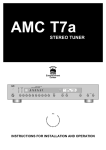
THE DINI GROUP LOGIC Emulation Source User Manual DNJTAG_USB LOGIC EMULATION SOURCE DNJTAG_USB User Manual Version 1.0 Date of Print May9, 2012 The Dini Group 7469 Draper Avenue La Jolla, CA92037 Phone 858.454.3419 • Fax 858.454.1728 [email protected] www.dinigroup.com Copyright Notice and Proprietary Information Copyright © 2012 The Dini Group. All rights reserved. No part of this copyrighted work may be reproduced, modified or distributed in any form or by any means, without the prior written permission of The Dini Group. Right to Copy Documentation The Dini Group permits licensee to make copies of the documentation for its internal use only. Each copy shall include all copyrights, trademarks, disclaimers and proprietary rights notices. Disclaimer The Dini Group has made reasonable efforts to ensure that the information in this document is accurate and complete. However, The Dini Group assumes no liability for errors, or for any incidental, consequential, indirect, or special damages, including, without limitation, loss of use, loss or alteration of data, delays, or lost profits or savings, arising from the use of this document or the product which it accompanies. Table of Contents INTRODUCTION ............................................................................................................................................................................................................... 1 1 2 3 4 5 GENERAL DESCRIPTION ............................................................................................................................................................................. 1 FEATURES .................................................................................................................................................................................................. 1 PACKAGE CONTENTS: ................................................................................................................................................................................ 2 INSPECT THE BOARD .................................................................................................................................................................................. 3 ADDITIONAL INFORMATION ....................................................................................................................................................................... 3 GETTING STARTED ........................................................................................................................................................................................................ 5 1 1.1 2 2.1 2.2 3 3.1 BEFORE YOU BEGIN ................................................................................................................................................................................... 5 Warnings ........................................................................................................................................................................................................... 5 BOARD SETUP ............................................................................................................................................................................................ 5 Before Powering Up the Board .......................................................................................................................................................................... 5 Powering Up the Board ..................................................................................................................................................................................... 6 INSTALLING THE SOFTWARE ...................................................................................................................................................................... 6 Installing USB to JTAG Converter Software (Windows 7)................................................................................................................................. 6 HARDWARE DESCRIPTION .......................................................................................................................................................................................... 7 1 2 2.1 2.2 3 3.1 4 4.1 OVERVIEW ................................................................................................................................................................................................. 7 SPECIAL REQUIREMENTS ........................................................................................................................................................................... 8 Requirements ..................................................................................................................................................................................................... 8 Additional Notes ................................................................................................................................................................................................ 8 LED INDICATORS ....................................................................................................................................................................................... 8 Power Supply LEDs ........................................................................................................................................................................................... 8 MECHANICAL ............................................................................................................................................................................................. 9 Custom Form Factor ......................................................................................................................................................................................... 9 List of Figures Figure 1 – DNJTAG_USB .................................................................................................................................................................................................................................. 1 Figure 2 – DNJTAG_USB Block Diagram.......................................................................................................................................................................................................... 7 List of Tables Table 1 – Power Supply LEDs.......................................................................................................................................................................................................................... 8 1 Chapter I N T R O D U C T I O N Introduction This User Manual accompanies the DNJTAG_USB. 1 General Description This DNJTAG_USB lets the user daisy chain up to 4 Xilinx JTAG devices and can communicate with these devices from outside a chassis via a USB-A to MICRO USBB cable. The PCI Express fingers only provide power to the DNJTAG_USB so it can be plugged into any width PCI Express slot and no external power is needed. 2 Features Figure 1 – DNJTAG_USB DNJTAG_USB User Manual www.dinigroup.com 1 I N T R O D U C T I O N DNJTAG_USB Board features the following: USB to JTAG converter (U3) 4 Xilinx JTAG 14-pin headers (J1, J2, J3, J4) LED Indicators o Power to the board (DS1) o Power from the JTAG cable (DS2) Clock Buffer (U4) Automatic bypass of unused JTAG connecters (U2, U5, U6) Two separate powering options (one or the other): o PCI Express fingers o External power connector (J5) for use without PCI Express power 12V, 25W power output (J6) – do not use without consulting The Dini Group first. Stiffener Bar Mounting holes for various mounting options o External chassis o PCI Bracket (standard/low profile) 3 Package Contents: Before using this board, be sure to inspect the board to verify that you received the correct item. If any of these items are missing, contact The Dini Group before you proceed. The DNJTAG_USB board kit includes the following: DNJTAG_USB Standard profile PCI bracket (attached to DNJTAG_USB) Stiffener (attached to DNJTAG_USB) DNJTAG_USB User Manual www.dinigroup.com 2 I N T R O D U C T I O N Low profile PCI bracket USB-A to MICRO USB-B cable (2m) 14-pin Xilinx JTAG cable, F/F PCI Express power output cable, F/F (do not use without consulting The Dini Group first) CD ROM containing: o User Manual (pdf format) o Schematic (pdf format) o Component Datasheets (pdf format) 4 Inspect the Board Place the board on an anti-static surface and inspect it to ensure that it has not been damaged during shipment. Verify that all components are on the board and appear intact. 5 Additional Information For additional information, please visit http://www.dinigroup.com/. The following table lists some of the resources you can access from this website. You can also directly access these resources using the provided URLs. Resource Description/URL User Manual This is the main source of technical information. The manual should contain most of the answers to your questions Dini Group Web Site The web page will contain the latest user manual, application notes, FAQ, articles, and any device errata and manual addenda. Please visit and bookmark: http://www.dinigroup.com E-Mail You may direct questions and feedback to the Dini Group using this e-mail address: [email protected] Phone Support Call us at 858.454.3419 during the hours of 8:00am to 5:00pm Pacific Time. FAQ The download section of the web page may contain a document called DNJTAG_USB Frequently Asked Questions (FAQ). DNJTAG_USB User Manual www.dinigroup.com 3 I N T R O D U C T I O N Resource Description/URL This document is periodically updated with information that may not be in the User Manual. DNJTAG_USB User Manual www.dinigroup.com 4 G E T T I N G 2 Chapter S T A R T E D Getting Started Congratulations on your purchase of the DNJTAG_USB. The remainder of this chapter describes how to start using the DNJTAG_USB. 1 Before You Begin 1.1 Warnings ESD Warning - The board is sensitive to static electricity, so treat the PCB accordingly. The target markets for this product are engineers that are familiar with FPGAs and circuit boards. However, if needed, the following web page has an excellent tutorial on the “Fundamentals of ESD” for those of you who are new to ESD sensitive products: http://www.esda.org/basics/part1.cfm Operating Temperature - Avoid touching the power supplies as these parts operate at high temperatures and may cause skin burns. 2 Board Setup The instructions in this section explain how to install the DNJTAG_USB. 2.1 Before Powering Up the Board Before powering up the board, prepare the board with one of the two options described below: Option 1: For use in a chassis, plug in board to any PCI Express slot Option 2: For use outside a chassis, remove PCI bracket and plug in J5. DNJTAG_USB User Manual www.dinigroup.com 5 G E T T I N G S T A R T E D 2.2 Powering Up the Board The DNJTAG_USB is powered by the PCI Express connector, or the floppy drive connector (J5). Turn on ATX power supply 3 Installing the Software 3.1 Installing USB to JTAG Converter Software (Windows 7) After board is powered on, plug in ‘USB-A to MICRO USB-B cable’ from your computer to the DNJTAG_USB. Windows update should install the needed driver automatically. The DNJTAG_USB is now ready to be used with the Xilinx tools. DNJTAG_USB User Manual www.dinigroup.com 6 H A R D W A R E 3 Chapter D E S C R I P T I O N Hardware Description This chapter describes the hardware features of the DNJTAG_USB 1 Overview A high level block diagram of the DNJTAG_USB is shown in Figure 2. Figure 2 – DNJTAG_USB Block Diagram Power can be sourced from PCI Express slot or floppy drive power. USB cable is used to interface to 1 to 4 Xilinx JTAG devices. LEDs are used to indicate power supply presence. PCI Express 12V, 25W power output (do not use without consulting The Dini Group first). DNJTAG_USB User Manual www.dinigroup.com 7 H A R D W A R E D E S C R I P T I O N 2 Special Requirements 2.1 Requirements Most of these requirements that are indicated on the back of the DNJTAG_USB 1. Must have Xilinx JTAG (J1) or Altera JTAG (J10) connected in order to use the others. 2. Cannot use both J1 and J10 at the same time. 3. All VREF have to be the same. 4. +VREF from Xilinx JTAG voltage range is 1.65V – 5.5V 2.2 Additional Notes Most of these notes are indicated on the back of the DNJTAG_USB 1. J5 is for non-PCIe usage 2. J6 25W power output should only be used after consulting The Dini Group. 3 LED Indicators 3.1 Power Supply LEDs Two green LEDs are provided to indicate the presence of +3.3V and +VREF. Table 1 – Power Supply LEDs Signal Name +3.3V +VREF DNJTAG_USB User Manual LED DS1 DS2 www.dinigroup.com 8 H A R D W A R E D E S C R I P T I O N 4 Mechanical 4.1 Custom Form Factor The DNJTAG board will fill in the slot next to any single slot board, but was specifically designed to fit in the slot next to the following Dini Group boards: DNBFC_S12_PCIE DNK7F5_PCIE DNPCIE_10G_HXT_LL Contact [email protected] compatibility. DNJTAG_USB User Manual for more information www.dinigroup.com about mechanical 9