1
FORCE GATE ARRAY FGA-002
User’s Manual
Edition No. 6
November 1996
P/N 201559
FORCE COMPUTERS Inc./GmbH
All Rights Reserved
This document shall not be duplicated, nor its contents used
for any purpose, unless express permission has been granted.
Copyright by FORCE COMPUTERS
I N D E X
1.
Introduction
2.
CPU and VME Interface
3.
Interrupt Management
4.
The 32 Bit DMA Controller
5.
Force Message Broadcast
6.
The Mailboxes
7.
The Timer
8.
Miscellaneous
9.
Register Format Short Description
10.
Boot Software
11.
User Notes / Product Error Report
(FMB)
As to Title Page, see separate File "Title.man"
CAUTION
The FGA-002 gate array contains registers, which are used to
configure
the
gate
array
for
special
external
hardware
requirements.
These registers are reserved and will be setup by the boot software
according to the hardware environment in which the gate array is
implemented.
These registers must not be changed by the user.
Some of these hardware configuration registers also contain user
selectable bits.
Programming the contents of these registers has to be
carefully without changing the bits initialized by the
software.
done
boot
Registers not described must not be programmed.
Unqualified changes of register bits may have unpredictable
consequences for the gate array and external hardware.
It is expressly forbidden to change register bits, except those
defined for the user.
User selectable registers and register bits are given in the
Register Format Short Description in section 7 of this manual.
They are designated with capital letters in the register format
scheme.
- i -
NOTE
Throughout the description, the terms active and inactive, asserted
and negated or set and cleared are used to designate a signal or
a register bit as true or false, independent of whether the signal
is active in the logic "1" state or the logic "0" state.
The default contents given for the register is the value after the
gate array has been reset and not the value which is programmed by
the boot software.
If no reference is made concerning the gate array support for dual
ported memory structure / shared memory structure, the described
gate array functions are common to both structures.
- ii -
INTRODUCTION
INTRODUCTION
The FGA-002 gate array is a high speed CMOS device manufactured in
1.2 micron technology and containing 24,000 gates in a 281 pin PGA
package.
It provides interfaces to the 68020/30 microprocessor as well as
a VMEbus compatible interface.
The auxilary interface of the gate array is a high speed data
channel used by the internal 32 bit DMA controller. The interface
allows data transfer rates of up to 6 MByte/second.
The timing of the local I/O interface is programmable and provides
easy interfacing of local I/O devices.
All control, address and data lines of the CPU and the VMEbus are
either directly connected or connected via buffers to the gate
array allowing easy implementation and usage.
The gate array registers are programmed by the local CPU.
FEATURES:
-
Programmable decoding for CPU and VME access to the local main
memory
-
Interrupt management for internal and external interrupt
sources
-
32 bit multi-port DMA Controller
-
FORCE Message Broadcast slave interface with
2 message channels
-
8 interrupt capable MAILBOXES
-
8 bit TIMER with 16 selectable internal source clocks
- iii -
INTRODUCTION
1.
1.1
The CPU Interface
Connected signals
The FGA-002 is directly connected to signal lines of the 68020/30
microprocessor. The following signals are connected:
PROCESSOR
Signals
32 address signals
32 data signals
Function code signals
Transfer size
Asynchronous bus control
A31..A00
D31..D00
FC2..FC0
SIZ0, SIZ1
AS,ECS,
R/W,RMC,
DSACK0,DSACK1
Synchronous bus control signal STERM,CIIN,CIOUT
Bus arbitration control signals BR,BG,
BGACK
Interrupt control signals,
IPL2..IPL0
Bus exception control signals
RESET,
HALT,
BERR
Processor clock
CLK
1.2
FGA-002
Signals
ACPU31..0
DCPU31..0
FC2..FC0
SIZE 0,1
ASCPU,ECS,
RWCPU,RMC
DSACK0,DSACK1
STERM,INHIN,INHOUT
BRCPU,BGCPU,
BGACK
IPL2..IPL0
RESCPU
HALT
BERRC
CKCPU
Decoding signals
The FGA-002 gate array decodes local address areas, secondary bus
areas and several areas for a VMEbus access.
The following
decoding outputs are supplied:
Local MAIN memory decoding signal
System eprom decoding signal
Local I/O area decoding signal
Secondary or VSBbus decoding signal
Co-processor decoding
CSDPR
CSPROM
CSLIO
CSVSB
CSCOPR
The local main memory map is software programmable. The memory
capacity is selectable from 64 Kbyte to 256 MByte.
The areas which decode accesses to the VMEbus are specially
designed to serve the needs of multi-processor applications.
- 1 -
INTRODUCTION
2.
The VMEbus Interface
The FGA-002 gate array is connected to the VMEbus via the
receiver/transmitter circuits.
The control signals for the
transceiver circuitry is also provided by the gate array.
Control of bus mastership/addressing in slave mode as well as a
single level bus arbiter and the bus mastership request/release
logic are also included in the FGA002.
The following VMEbus signals are applied to the gate array:
VMEbus
signals
Addressing signals
A31..A01
LWORD
Address Modifier signals AM5..AM0
Data signals
D31..D00
Asynchronous bus control AS*,DS1*,DS0*
WRITE*,DTACK*
DTACK*, BERR*
Bus arbitration signals BRx*
BGxIN*
BGxOUT*
BBSY*
BCLR*
Interrupt signals
IRQ 7..1
Utility signals
SYSRESET*
ACFAIL*
SYSFAIL*
FGA-002
signals
AVME31..01
LWDVME
AM5..0
DVME31..00
ASVME,DS1,DS0
RWVME
DTACK,BERRV
BRVMEO, BRVMEI
BGVMEI
BGVMEO
BBSYO,BBSYI
BCLRI
VIRQ 7..1
RESVO, RESVI
ACFAIL
SFAILO, SFAILI
There is a decoding range defined for accesses from the VMEbus to
the local main memory. The FGA-002 gate array decodes all address
and address modifier signals. The address range for the main memory
is software programmable with the lowest boundary at 4 KByte.
Several Address Modifier Codes are selectable for a valid memory
decoding. It is selectable if the decoding is valid for Read only
or Read and Write cycles. This allows on-board memory to be
protected from being overwritten by VMEbus accesses.
The gate array includes slot 1 functions such as the Single Level
Arbiter and the SYSRESET generator.
Several release options for the VMEbus are provided.
Timing and enable of the bus release options are software
selectable.
The following bus release functions can be selected:
Release on request
(ROR)
Release on Bus Clear
(RBCLR)
Release voluntary
(RV)
Release on ACFAIL
(RACFAIL)
- 2 -
INTRODUCTION
3.
The Interrupt Management
The FGA002 includes several internal interrupt sources which are
fully under software control.
Additionally, 11 interrupt inputs are provided for utility
interrupts and those from local I/O devices. The 7 interrupts from
the VMEbus may also be connected.
The interrupt of each source can be mapped to any level for service
request from the local CPU.
Except for the VMEbus interrupts, the gate array supplies an
individual interrupt vector for each interrupt source.
Four local interrupt request channels support fetching the
interrupt vector from the interrupting device through the local I/O
interface.
4.
The DMA Controller
The 32 bit high speed DMA controller operates to the local cpu bus,
the VMEbus and to the auxilary bus.
The DMA controller uses an internal 32 byte deep FIFO to minimize
the number of transfer cycles. If the source and destination
addresses are aligned, the data is transferred in bursts of 32
bytes.
The DMA controller uses the local bus or the VMEbus continuously
only for the time of a transfer burst. This guarantees realtime
capability of the system since neither the VME master nor the local
cpu is blocked in its operation.
The DMA controller executes 68020/30 compatible cycles on the local
side and uses the VME interface for VMEbus compatible transfer
cycles.
- 3 -
INTRODUCTION
5.
FORCE MESSAGE BROADCAST -FMB-
The FORCE Message Broadcast Concept is realized inside the FGA-002
gate array.
The FMB concept allows up to 20 CPU boards on the VMEbus to be
synchronized using interrupts. The interrupt is performed by
simultaneously sending each board a message byte. Any VME master
with 32 bit addressing capability can accomplish an FMB broadcast
cycle.
The implementation of the FMB concept in the FGA-002 is realized
with two individual message channels, each able to perform two
interrupt requests.
While the 8 byte FIFO of channel 0 allows several messages to be
sent in succession, channel 1 with its one byte FIFO can be used
for prioritized messages.
In the current version of the FGA-002 gate array, 8 bit wide
messages can be received.
6.
THE MAILBOXES
The FGA-002 includes 8 mailboxes. The dual ported mailboxes are
accessible by the local processor as well as by VME masters.
The mailboxes provide a means to synchronize multiple cpu boards
by sending them an interrupt.
The mailboxes also can be used as semaphores for the
allocation of system resources used by several masters in common.
7.
The Timer
There is an 8 bit timer included in the FGA-002 gate array.
The timer can be used as a periodical timer or as a watchdog timer,
generating a sysfail signal to the VMEbus.
The timer generates
programmable level.
an
interrupt
request
with
a
software
The clock source for the timer is software selectable from one of
16 internally generated clocks.
- 4 -
INTRODUCTION
8.
History of Manual Revisions
Revision 1:
Complete Rework of Manual.
Revision 2:
The following Sections/Chapters have been edited as
indicated below:
Section 1 "INTRODUCTION", Chapter 1.1 "Connected
signals":
Under "PROCESSOR Signals", AS,DS has been changed
to AS,ECS,; STERM has been changed to STERM,CIIN,
CINOUT.
Under "FGA-002 Signals, ASCPU,DSCPU has
been changed to ASCPU,ECS,; STERM has been changed
to STERM,INHIN,INHOUT.
Section 1 "INTRODUCTION", Chapter 2 "The VMEbus
Interface":
Under "FGA-002 Signals", VIRQ 7..0 is now VIRQ
7..1.
Revision 3:
Section 10, "The FGA-002 Gate Array Boot Software"
has been updated to comply with the FGA-002 boot
software Version 3.1.
Revision 4:
Section 3, "Interrupt Management":
Page 2-23:
0 and 1 were switched by Autoclear.
Section 4, "The 32 Bit DMA Controller":
Page 3-4:
0 and 1 were switched by bits 3 & 4
of the attribute code.
Section 9, "Register Format Short Description":
Page 8:
Bits 0, 1, and 2 were switched.
Page 30:
Bit 1 was added.
Page 31:
Bits 3, 4, 5, 6, and 7 were added.
Revision 5:
Section 2, "The VME Interface"
Page 2-5:
Table 2-2 corrected for Standard A24
NDA
- 5 -
CPU AND VME
INTERFACE
This page was intentionally left blank
THE CPU AND VME INTERFACE
TABLE OF CONTENTS
1.
2.
CPU INTERFACE
. . . . . . . . . . . . . . . . .
1.1 FEATURES
. . . . . . . . . . . . . . . . .
1.2 ADDRESS DECODING STRUCTURE
. . . . . . . .
1.3 MAIN MEMORY . . . . . . . . . . . . . . . .
1.3.1
The MAIN MEMORY Decoding Registers
1.3.2
The MAIN MEMORY ENABLE Bit
. . .
1.3.2.1
Register CTL11
. . . .
1.3.3
The MAIN MEMORY SIZE
. . . . . .
1.3.3.1
Register CTL11
. . . .
1.3.3.2
Register CTL10
. . . .
1.3.4
The MAIN MEMORY BASE ADDRESS
. .
1.3.4.1
Register MAINUU . . . .
1.3.4.2
Register MAINUM . . . .
1.3.5
The MAIN MEMORY DSACK/STERM . . .
1.3.5.1
Register CTL11 . . . .
1.3.5.2
Register CTL16 . . . .
1.4 VSB BUS SELECT
. . . . . . . . . . . . . .
1.4.1
Register CTL3
. . . . . . . . .
1.5 SECONDARY Bus (D32) . . . . . . . . . . . .
1.6 SECONDARY Bus (D16) . . . . . . . . . . . .
1.7 SYSTEM EPROM Decoding Area
. . . . . . . .
1.7.0.1
Register CTL14 . . . .
1.7.1
SYSTEM EPROM DSACK Control
. . .
1.7.1.1
Register CTL9
. . . .
1.8 LOCAL I/O AREA
. . . . . . . . . . . . .
1.8.1
LOCAL I/O Page A: FF8X XXXX
. .
1.8.2
LOCAL I/O Page B: FF9X XXXX
. .
1.8.3
LOCAL I/O Page C: FFAX XXXX
. .
1.8.4
LOCAL I/O Page D: FFBX XXXX . . .
1.8.5
BOOT SRAM : FFCX XXXX . . . . . .
1.8.6
THE GATE ARRAY ITSELF: FFDX XXXX
1.8.7
BOOT EPROM: FFEX XXXX . . . . . .
1.8.8
LOCAL I/O Page E: FFFX XXXX . . .
1.9 ACCESS TO FGA-002 REGISTERS . . . . . . . .
1.9.1
Supervisor/User Access
. . . . .
1.9.1.1
Register CTL1
. . . .
1.9.2
DSACK Control . . . . . . . . . .
1.9.2.1
Register CTL6
. . . .
1.10 BOOT DECODING FEATURES
. . . . . . . . . .
VME MASTER INTERFACE . . . . . . . . . . . . . .
2.1 FEATURES
. . . . . . . . . . . . . . . . .
2.2 Description . . . . . . . . . . . . . . . .
2.3 Addressing Capability
. . . . . . . . . .
2.3.1
Address Modifier Signal Generation
2.4 Data Transfer Capability
. . . . . . . . .
2.4.1
D16 Master Option . . . . . . . .
2.4.1.1
Register CTL3
. . . .
2.4.2
Support for Unaligned RMW cycles
2.4.2.1
Register CTL16 . . . .
.
.
.
.
.
.
.
.
.
.
.
.
.
.
.
.
.
.
.
.
.
.
.
.
.
.
.
.
.
.
.
.
.
.
.
.
.
.
.
.
.
.
.
.
.
.
.
1-1
1-1
1-2
1-4
1-4
1-6
1-6
1-7
1-7
1-7
1-8
1-9
1-9
1-10
1-10
1-10
1-11
1-11
1-11
1-11
1-12
1-12
1-13
1-13
1-14
1-15
1-15
1-15
1-15
1-16
1-16
1-16
1-16
1-16
1-17
1-17
1-18
1-18
1-19
2-1
2-1
2-2
2-2
2-4
2-6
2-9
2-10
2-11
2-11
THE CPU AND VME INTERFACE
TABLE OF CONTENTS (cont’d)
2.5
2.6
2.7
3.
VMEbus ARBITRATION
. . . . . . . . . . . . .
2.5.1
Automatic Re-Arbitration
. . . . .
2.5.2
Internal/External Arbiter select
.
2.5.2.1
Register CTL1
. . . . .
VMEbus REQUEST
. . . . . . . . . . . . . . .
2.6.1
VMEbus request on power fail detection
2.6.2
FAIR request option . . . . . . . .
2.6.2.1
Register CTL8
. . . . .
VMEbus RELEASE
. . . . . . . . . . . . . . .
2.7.1
Release On Request (ROR)
. . . . .
2.7.1.1
Register CTL7
. . . . .
2.7.2
Release on Bus Clear
. (RBCLR)
. . . . . . . . .
2.7.2.1
Register CTL7
. . . . .
2.7.3
Release Voluntary (RV)
. . . . . .
2.7.4
Release on ACFAIL* (RACFAIL)
. . .
2.7.5
Release Every Cycle (REC) . . . . . .
2.7.5.1
Register CTL12 . . . . . .
2-12
2-13
2-13
2-13
2-14
2-14
2-14
2-15
2-16
2-16
2-17
2-18
2-18
2-19
2-19
2-20
2-20
VME SLAVE INTERFACE
. . . . . . . . . . . . . . .
3-1
3.1 FEATURES
. . . . . . . . . . . . . . . . . .
3-1
3.2 VME Access to the local MAIN MEMORY . . . . .
3-2
3.2.1
Decoding scheme for accesses to the local
MAIN memory from the VMEbus side
.
3-3
3.2.2
VME Page Decoding
. . . . . . . .
3-4
3.2.2.1
Register VMEPAGE . . . .
3-4
3.2.3
VME Interval Decoding
. . . . . .
3-5
3.2.3.1
Registers for Bottom and Top
page selection
. . . . .
3-5
3.2.4
Enable Address Modifier Decoding
.
3-7
3.2.4.1
Register ENAMCODE
.
3-8
3.3 Shared Memory Structure Support
. . . . . . . . . . . 3-9
3.3.1
RMW Cycles from VME to the MAIN Memory 3-10
3.3.1.1
Register CTL15 . . . . .
3-10
3.4 VME Access to FGA-002 functions . . . . . . .
3-11
3.4.1
VME page selection
. . . . . . . .
3-12
3.4.1.1
Register MYVMEPAGE . . .
3-12
3.4.2
Address Modifier Code selection . .
3-13
3.4.2.1
Register CTL5
. .
3-13
THE CPU AND VME INTERFACE
LIST OF FIGURES
Figure 1-1: Masking scheme for the base address register
bits
. . . . . . . . . . . . . . . . . . .
1-9
THE CPU AND VME INTERFACE
LIST OF TABLES
Table 1-1:
Table 1-2:
Table 1-3:
Table 1-4:
Table 2-1:
Table 2-2:
Table 2-3:
Table 2-4:
The 32bit Address Decoding Map
MAIN MEMORY control overview
Address assignment of the local
control registers
. . . . . .
MAIN MEMORY SIZE
. . . . . .
. . . .
. . . . .
MAIN MEMORY
. . . . .
. . . . .
Address ranges of the VMEbus areas with
addressing capability and data transfer
capability (Axx : Dxx)
. . . . . . . .
Supported Address Modifier Codes for CPU
access to the VMEbus areas
. . . . . .
Supported Data Transfer Types for D16 MASTER
and D08 MASTER capability
. . . . . .
Supported Data Transfer Types for D32, D16
and D08 MASTER capability
. . . . . . .
1-3
1-5
1-5
1-7
2-3
2-5
2-7
2-8
THE CPU AND VME INTERFACE
This page was intentionally left blank
THE CPU INTERFACE
1
CPU INTERFACE
1.1
FEATURES
- programmable main memory decoding
- programmable main memory size
- programmable DSACK/STERM timing for main memory access
- programmable DSACK timing for user eprom access
- Supervisor/User mode select for gate array register access
- programmable DSACK timing for gate array register access
- LOCAL I/O decoding pages with selectable timing parameters
1-1
THE CPU INTERFACE
1.2
ADDRESS DECODING STRUCTURE
The Gate Array decoding logic involves a 4 GByte address space
to control the access to the local MAIN MEMORY, the VMEbus, the
VSB bus, the secondary bus and the Local I/O Area.
The decoding logic contains hard wired decoding logic and
software programmable decoding logic.
Software programmable decoding is realized for the local MAIN
MEMORY. The size and the base address can be selected.
For the remaining areas hard wired decoding is included.
The address range $0000 0000 - $FAFF FFFF is shared by the
local MAIN MEMORY, the Extended VMEbus address range and the
VSB bus selection.
The address range $FB00 0000 ...$FFFF FFFF contains five
16MByte pages, four pages for additional VMEbus and secondary
bus decoding and one page for the SYSTEM EPROM and the LOCAL
I/O Area.
The LOCAL I/O decoding area is provided to select devices which
are connected to the Gate Array’s Local I/O bus such as the
BOOT SRAM, the BOOT EPROM and diverse I/O devices.
The following table shows the 32bit decoding map for the 4GByte
address space of the CPU.
1-2
THE CPU INTERFACE
Table 1-1:
The 32bit Address Decoding Map
0000 0000
:::: ::::
MAIN MEMORY
A32 : D32
:::: ::::
VSB Bus
A32 : D32
: D16
: D8
:::: ::::
VMEbus Extended Address Range
A32 : D32
: D16
FB00 0000
:::: ::::
FBFE FFFF
VMEbus Standard Address Range
with 32 bit data bus
A24 : D32
FBFF XXXX
VMEbus Short
Address Range
with 32 bit data bus
A16 : D32
FC00 0000
:::: ::::
FCFE FFFF
VMEbus Standard Address Range
with 16 bit data bus
A24 : D16
FCFF XXXX
VMEbus Short
Address Range
with 16 bit data bus
A16 : D16
SECONDARY bus
Address Range
with 32 bit data bus
A24 : D32
SECONDARY bus
Address Range
with 16 bit data bus
A24 : D16
FAFF FFFF
FBXX XXXX
FCXX XXXX
FDXX XXXX
FD00 0000
:::: ::::
FDFF FFFF
FEXX XXXX
FE00 0000
:::: ::::
FEFF FFFF
1-3
THE CPU INTERFACE
Table 1-1 : cont’d
FFXX XXXX
FF00 0000
:::: ::::
FF7F FFFF
FF80 0000
:::: ::::
:::: ::::
FFFF FFFF
SYSTEM EPROM Area
A23 : D32
LOCAL I/O
A23 : D08
FF8X
FF9X
FFAX
FFBX
FFCX
FFDX
FFEX
FFFX
XXXX
XXXX
XXXX
XXXX
XXXX
XXXX
XXXX
XXXX
Area
:
:
:
:
:
:
:
:
LOCAL I/O Page A
LOCAL I/O Page B
LOCAL I/O Page C
LOCAL I/O Page D
BOOT SRAM
GATE ARRAY Registers
BOOT EPROM
LOCAL I/O Page E
1.3
MAIN MEMORY
1.3.1
The MAIN MEMORY Decoding Registers
A20
A20
A20
A20
A20
A20
A20
A20
:
:
:
:
:
:
:
:
D08
D08
D08
D08
D08
D08
D08
D08
The local MAIN MEMORY decoding is realized as software
programmable decoding logic. The decoding logic includes
registers for the selection of the memory size and the local
base address. The registers can be programmed by the local cpu.
A set of two registers has to be programmed for the memory size
as well as for the base address selection.
The local sided MAIN MEMORY decoding can be enabled/disabled by
a single bit in the register CTL11.
During the initialization of the MAIN MEMORY decoding
registers, the decoding should be disabled by this bit.
To terminate access cycles to the MAIN MEMORY, the STERM signal
or the DSACKx termination signal can be selected. Both
termination modes indicate to the processor a long word port
size. The timing of these signals is controlled by the CTL11
and the CTL16 registers.
1-4
THE CPU INTERFACE
The first of the following tables gives an overview of the
registers and the corresponding bits, which are used to select
the local sided decoding area and the cycle termination mode
for MAIN MEMORY accesses.
The second table shows the address assignment for these
registers.
Table 1-2:
MAIN MEMORY control overview
REGISTER
CTL11
Bits
SIZE
3210
CTL10
Bits
MAINUM
Bits
CTL16
Bits
76543210
76543210
76543210
BASE
ENABLE
MAINUU
Bits
7
DSACK
654
STERM
Table 1-3:
210
Address assignment
control registers
of
the
local
MAIN
MEMORY
Register
Mnemonic
Address
R/W
Default
Control Register 10
Control Register 11
Base Address Reg. UM
Base Address Reg. UU
Control Register 16
CTL10
CTL11
MAINUM
MAINUU
CTL16
$FFD002C0
$FFD002C4
$FFD002C8
$FFD002CC
$FFD0035C
R/W
R/W
R/W
R/W
R/W
$00
$00
$00
$00
$00
1-5
THE CPU INTERFACE
1.3.2
The MAIN MEMORY ENABLE Bit
Bit 7 of the CTL11 register selects if the local sided MAIN
MEMORY decoding is enabled or disabled.
After reset, the register is cleared to 0 which disables the
decoding.
During the initialization of the MEMORY SIZE and the MEMORY
BASE address, the bit should be cleared to disable the decoding
logic.
1.3.2.1
7
MAIN
ENA
7
1
0
Register CTL11
6
5
4
2
1
0
S27
S26
S25
S24
MAIN DSACK
3
MAIN ENA -
This bit is used to enable/disable the
local sided MAIN MEMORY decoding area.
enabled
disabled
1-6
THE CPU INTERFACE
1.3.3
The MAIN MEMORY SIZE
The SIZE of the local MAIN MEMORY is programmed in the CTL10
and CTL11 registers.
The bits S27..S16 select the SIZE in
ranges of 64 KByte up to 256 MByte.
1.3.3.1
Register CTL11
7
6
MAIN
ENA
5
4
MAIN DSACK
1.3.3.2
3
2
1
0
S27
S26
S25
S24
Register CTL10
7
6
5
4
3
2
1
0
S23
S22
S21
S20
S19
S18
S17
S16
The following table summarizes the selectable memory sizes.
Other combinations are not allowed!
Table 1-4:
MEMORY SIZE
256 MByte
128 MByte
64 MByte
32 MByte
16 MByte
8 MByte
4 MByte
2 MByte
1 MByte
512 KByte
256 KByte
128 KByte
64 KByte
MAIN MEMORY SIZE
CTL11
CTL10
S27 S26 S25 S24
S23 S22 S21 S20 S19 S18 S17 S16
0
1
1
1
1
1
1
1
1
1
1
1
1
0
0
1
1
1
1
1
1
1
1
1
1
1
0
0
0
1
1
1
1
1
1
1
1
1
1
0
0
0
0
1
1
1
1
1
1
1
1
1
0
0
0
0
0
1
1
1
1
1
1
1
1
1-7
0
0
0
0
0
0
1
1
1
1
1
1
1
0
0
0
0
0
0
0
1
1
1
1
1
1
0
0
0
0
0
0
0
0
1
1
1
1
1
0
0
0
0
0
0
0
0
0
1
1
1
1
0
0
0
0
0
0
0
0
0
0
1
1
1
0
0
0
0
0
0
0
0
0
0
0
1
1
0
0
0
0
0
0
0
0
0
0
0
0
1
THE CPU INTERFACE
1.3.4
The MAIN MEMORY BASE ADDRESS
The base address for the local main memory has to be defined
within the address range $0000 0000 ... $FAFF FFFF.
A set of two registers is provided for the base address
selection:
MAINUU register
MAINUM register
The following terms are used to designate the address bytes of
a 32 bit address value.
Address bits
Address byte
A31..A24
A23..A16
A15..A08
A07..A00
Upper-Upper
Upper-Middle
Lower-Middle
Lower-Lower
Byte
Byte
Byte
Byte
The local base address of the main memory can be selected by
assigning the value of the upper-upper address byte (A31..A24)
to the MAINUU register and the upper-middle byte (A23..A16) to
the MAINUM register.
The base address decoding is performed by a comparison of the
CPU address lines A31..A16 with the register bits B31..B16 of
the BASEUU and the BASEUM register. The main memory is
addressed when the CPU address signals match the register bit
pattern stored in the bits B31..B16.
To determine which values have to be written into the base
address registers, the programmed main memory size also has to
be taken into account.
When the memory size is selected to be greater than 64 Kbyte,
the base address register bits B27..B16 will be masked by the
SIZE bits S27..S16. In this case, the masked base address bits
can be ignored and need not be initialized.
A base address register bit is masked, if "0" is stored in the
corresponding SIZE register bit.
A masked base address register bit will not be compared for the
base address decoding.
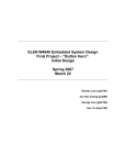
The masking scheme is demonstrated in figure 1-1.
1-8
THE CPU INTERFACE
Figure 1-1: Masking scheme for the base address register bits
CPU Address signals
A31 A30 A29 A28 A27 A26 A25 A24 A23 A22 A21 A20 A19 A18 A17 A16
S27 S26 S25 S24 S23 S22 S21 S20 S19 S18 S17 S16
SIZE selection bits
"0" means that the bit Bxx will not be compared
B31 B30 B29 B28 B27 B26 B25 B24 B23 B22 B21 B20 B19 B18 B17 B16
MAINUU
Base address register bits
1.3.4.1
MAINUM
Base address register bits
Register MAINUU
7
6
5
4
3
2
1
0
B31
B30
B29
B28
B27
B26
B25
B24
7..0
1.3.4.2
B31..B24 -
These bits are used to define the
the Upper-Upper byte of the main
memory base address. The bits will
be compared with the CPU address
signals A31..A24.
Register MAINUM
7
6
5
4
3
2
1
0
B23
B22
B21
B20
B19
B18
B17
B16
7..0
B23..B16 -
These bits are used to select the
Upper-Middle byte of the main
memory base address. The bits will
be compared with the CPU address
signals A23..A16.
1-9
THE CPU INTERFACE
1.3.5
The MAIN MEMORY DSACK/STERM
Access cycles to the MAIN MEMORY area are terminated either
with the DSACKx signals for a long word port, or with the
synchronous STERM output signal, generated by the gate array.
The timing of the signals can be selected by the registers
CTL11 for the DSACK signal and CTL16 for the STERM signal.
The timing is given as a number of waitstates, which the
processor has to insert before the cycle will be terminated.
Three timing options are offered for the DSACK signals and the
STERM signal.
After reset, the registers are cleared to zero and no
termination mode is selected.
1.3.5.1
7
Register
6
MAIN
ENA
6..4
CTL11
5
4
MAIN DSACK
MAINDSACK -
7
Register
6
1
0
S27
S26
S25
S24
CTL16
5
URMW
VMETIMEOUT
2..0
MAINSTERM
000
001
010
100
2
This bit field is used to select the
DSACK timing for an access to the local
MAIN MEMORY.
No DSACK Generation
0-Waitstate DSACK
1-Waitstate DSACK
2-Waitstate DSACK
000
001
010
100
1.3.5.2
3
-
4
3
PEB
PEA
2
1
0
MAIN STERM
This bit field is used to select the
STERM timing for an access to the local
MAIN MEMORY.
No STERM Generation
0-Waitstate STERM
1-Waitstate STERM
2-Waitstate STERM
1-10
THE CPU INTERFACE
1.4
VSB BUS SELECT
An access to the VSB bus is indicated by the VSB select signal
CSVSB. This signal is low when the VSBbus is decoded. A
register bit in the CTL3 register enables the VSB bus
selection.
If the bit "VSBENA" is set, all accesses to the decoded VMEbus
Extended Address Range will lead to a VSB bus access.
The VSB bus access will be refused and redirected to a VMEbus
access when the gate array input pin NOVSB is asserted low.
1.4.1
Register
CTL3
Register
Control 3
Register
Mnemonic
Address
R/W
Default
CTL3
$FFD00250
R/W
$00
Format of CTL3
7
6
5
4
3
2
VECTOR
BIT 7
BIT 6
7
1
0
1.5
VSBENA -
1
VSBENA
0
OPT16
This bit is used to control the VSB bus
decoding
VSB bus decoding enabled
VSB bus decoding disabled
SECONDARY Bus (D32)
The address range $FD00 0000 ... $FDFF FFFF is decoded for
accesses to a Secondary bus with 32 bit data bus width.
A valid decoding of this area is indicated by the output signal
CSVSB.
1.6
SECONDARY Bus (D16)
The address range
$FE00 0000 ... $FFEF FFFF is decoded for
accesses to a Secondary bus with 16 bit data bus width.
A valid decoding of this area is indicated by the output signal
CSVSB.
1-11
THE CPU INTERFACE
1.7
SYSTEM EPROM Decoding Area
The SYSTEM EPROM area is decoded in
the address range
$FF000000 - $FF7FFFF.
The Gate Array pin CSPROM is low when this area
By default, only read accesses to this area
However, a control bit can be programmed to
accesses as well. This feature may be useful in
hardware configurations.
The enable bit SEPROMWRITE for write accesses
EPROM area is contained in the register CTL14.
1.7.0.1
Register
is decoded.
are allowed.
enable write
special board
to the SYSTEM
CTL14
Register
Mnemonic
Address
R/W
Default
Control 14 Register
CTL14
$FFD00354
R/W
$00
Format of CTL14
7
6
SEPROM
WRITE
BSCUT
7
1
0
5
4
VMEDTACKEVAL
SEPROMWRITE -
3
2
DSVMEWRITE
1
0
ASTOVME
This bit selects if the SYSTEM EPROM
area is also decoded for write cycles.
read and write cycles possible
only read cycles possible
1-12
THE CPU INTERFACE
1.7.1
SYSTEM EPROM DSACK Control
Access cycles to the SYSTEM EPROM area will be terminated by a
Long Word DSACK signal, generated by the Gate Array.
The timing of the DSACK signals can be selected in the CTL9
register.
This register selects the number of waitstates the processor
has to insert before the cycle will be terminated.
After reset, the CTL9 register is cleared to 0 and the DSACK
generation for SYSTEM EPROM accesses is disabled by default.
1.7.1.1
Register
CTL9
Register
Mnemonic
Address
R/W
Default
Control 9 Register
CTL9
$FFD0027C
R/W
$00
Format of CTL9
7
6
5
4
-
-
-
-
2..0
000
001
010
011
100
101
110
111
SEPROMDSACK -
3
2
RESET
OPTION
1
0
SEPROMDSACK
This bit field selects the number of
waitstates for data cycles to the
SYSTEM EPROM decoding area.
No DSACK Generation
0 Waitstate DSACK
1 Waitstate DSACK
2 Waitstate DSACK
3 Waitstate DSACK
4 Waitstate DSACK
5 Waitstate DSACK
6 Waitstate DSACK
1-13
THE CPU INTERFACE
1.8
LOCAL I/O AREA
The Gate Array decodes the LOCAL I/O Area in the following
address range:
$FF80 0000 ... $FFFF FFFF
The LOCAL I/O Area is split into eight pages. Six pages can be
used to decode onboard devices connected to the Gate Array’s
byte wide LOCAL I/O bus.
When these pages are accessed, the Data transfer to the onboard
devices is performed via the LOCAL I/O interface of the gate
array, which executes an individual timing protocol, selectable
in the register LIOTIMING for the LOCAL I/O pages A - D.
One page selects the Gate Array itself and another one a
special LOCAL I/O page, which is not supported by the LOCAL I/O
interface.
A valid decoding of the LOCAL I/O Area is indicated by a low
level on the output pin CSLIO of the gate array.
The various pages of the LOCAL I/O Area have to be decoded with
external hardware using the processor address lines A22..A20
and the signal CSLIO, generated by the gate array.
In order to decode the BOOT EPROM area during the boot-up
procedure, the address signal A23 needs to be included as well.
Please refer to the chapter "BOOT DECODING FEATURES" for more
details.
The LOCAL I/O interface is implemented with a byte wide data
bus and consists of the following signals:
Signal Name
Function
CSLIO
RDLIO
WRLIO
DLIO 0-7
LOCAL I/O Area Select
Read Strobe
Write Strobe
Data Lines
1-14
THE CPU INTERFACE
The LOCAL I/O Pages are defined as follows:
Address Range
Definition
FF8X
FF9X
FFAX
FFBX
FFCX
FFDX
FFEX
FFFX
LOCAL I/O Page A
LOCAL I/O Page B
LOCAL I/O Page C
LOCAL I/O Page D
BOOT SRAM
GATE ARRAY Registers
BOOT EPROM
LOCAL I/O Page E
XXXX
XXXX
XXXX
XXXX
XXXX
XXXX
XXXX
XXXX
:
:
:
:
:
:
:
:
The LOCAL I/O pages A - D can be used to select onboard devices
whose access protocol meets one of the timing parameters
provided for the LOCAL I/O pages A - D. The devices must be
connected to the LOCAL I/O interface. Accesses to these pages
are terminated with a byte DSACK to the processor.
1.8.1
LOCAL I/O Page A: FF8X XXXX
This page selects the LOCAL I/O Interface with an access time
for R/W cycles, defined by the bits 1..0 of the LIOTIMING
register.
1.8.2
LOCAL I/O Page B: FF9X XXXX
This page selects the LOCAL I/O Interface with an access time
for R/W cycles, defined by the bits 3..2 of the LIOTIMING
register.
1.8.3
LOCAL I/O Page C: FFAX XXXX
This page selects the LOCAL I/O Interface with an access time
for R/W cycles, defined by the bits 5..4 of the LIOTIMING
register.
1.8.4
LOCAL I/O Page D: FFBX XXXX
This page selects the LOCAL I/O Interface with an access time
for R/W cycles, defined by the bits 7..6 of the LIOTIMING
register.
1-15
THE CPU INTERFACE
1.8.5
BOOT SRAM : FFCX XXXX
This LOCAL I/O page is decoded for the BOOT SRAM device. A
DSACK signal code for an 8 bit port is generated to terminate
accesses to this page.
1.8.6
THE GATE ARRAY ITSELF: FFDX XXXX
This page selects the Gate Array itself. Cycle termination is
performed with long DSACK. Accesses to the gate array registers
are indicated by a low CSLIO signal. For more details please
refer to the chapter "Access to FGA-002 Registers" in this
section.
1.8.7
BOOT EPROM: FFEX XXXX
This page is reserved for the BOOT EPROM device. A byte DSACK
signal is generated for this page. Please refer to the chapter
"BOOT Decoding Features" for more details.
1.8.8
LOCAL I/O Page E: FFFX XXXX
This page is usable as a special decoding area and for devices
whose timing does not meet the protocols provided for the timed
LOCAL I/O pages. Since the interface does nothing if this page
is addressed, the device has to be directly connected to the
CPU data bus. An access to this address range is indicated by
a low CSLIO signal.
The FGA-002 Gate Array does not generate a DSACK for this page.
1.9
ACCESS TO FGA-002 REGISTERS
The FGA-002 Gate Array Registers can only be accessed via the
cpu interface of the gate array. The address range, which
decodes the gate array registers, is located within the LOCAL
I/O Area from $FFD00000 to $FFDFFFFF.
The 8 bit registers can be accessed with byte, word or longword
operand sizes. 32 bit registers must be accessed with longword
operands.
1-16
THE CPU INTERFACE
1.9.1
Supervisor/User Access
The 680X0 processor family defines two privileged levels of
operation: the Supervisor privilege level and the User
privilege level.
In which privilege level the processor has to perform a legal
access to the gate array is defined by bit 3 of the control
register CTL1.
Bit 3 of the register CTL1 selects either the Supervisor access
type or Supervisor and User access type to be valid.
If the bit is cleared, the gate array can be accessed not only
in the Supervisor access mode but also in the User access mode.
The Supervisor privilege level is selected if the bit is set to
1.
After reset, the CTL1 register bits are cleared to 0.
This selects both the User and the Supervisor privilege levels
as being valid access types.
1.9.1.1
Register
CTL1
Register
Mnemonic
Address
R/W
Default
Control 1 Register
CTL1
$FFD00238
R/W
$00
Format of CTL1
7
6
5
4
-
-
-
-
3
1
0
3
SUP/
USR
2
ARBITER
1
0
CSCO
SUP/USR - The bit selects the access mode to the
FGA-002 registers
Access only in Supervisor mode
Access in Supervisor and User mode
1-17
THE CPU INTERFACE
1.9.2
DSACK Control
The gate array terminates an access to its registers by
asserting the DSACK0 and DSACK1 output pins to 0, indicating a
Long Word port size to the processor.
The timing of the DSACKx signals is software selectable by the
register CTL6.
This register is used to select the number of waitstates the
processor has to insert before the cycle is complete.
After reset, the CTL6 register is cleared to 0 and the gate
array will terminate bus cycles with 4 waitstates.
1.9.2.1
Register
CTL6
Register
Mnemonic
Address
R/W
Default
Control 6 Register
CTL6
$FFD00270
R/W
$00
Format of CTL6
7
6
5
4
-
-
-
-
3..0
0000
0001
0010
0100
1000
3
2
1
0
MYDSACK
MYDSACK - This bit field selects the number of waitstates for access cycles to the gate array
registers.
4
0
1
2
3
Waitstate
Waitstate
Waitstate
Waitstate
Waitstate
1-18
DSACK
DSACK
DSACK
DSACK
DSACK
THE CPU INTERFACE
1.10
BOOT DECODING FEATURES
After the gate array has been reset, the normal address
decoding structure will be disabled and a special area decoding
(BOOT decoding) is active. This BOOT decoding comes into effect
when the BOOTFLAG is zero. The decoding is used to support the
boot procedure for the processor. The BOOTFLAG is a
readable/writable register bit, which is cleared to 0 after
every boot reset. The BOOTFLAG is bit 0 of the CTL4 Register in
the Gate Array.
As long as the BOOTFLAG = 0, the decoding structure is changed
in such way that the LOCAL I/O Area will be selected in the
whole 32 bit address space.
When the BOOT decoding is active, the LOCAL I/O Interface has
the timing parameters of the BOOT EPROM page.
The BOOT EPROM and the Gate Array itself are always accessible
at their correct address according to the LOCAL I/O Page
decoding address map.
In order to boot the 680X0 processors from the address 0,
the BOOT EPROM must to be the only device selected when the
BOOTFLAG is active.
Therefore, external decoding logic has to provide the decoding
signal for the BOOT EPROM, which is then asserted in the
following cases:
1.
2.
The decoding area of the BOOT EPROM is addressed. (FFEX
XXXX)
The output pin CSLIO is asserted and one of the CPU
address lines A31-A23 is in a low state.
The boot information has to lead the program flow to the normal
address range of the BOOT EPROM decoding area. Then, the first
action should be to write a 1 to the
BOOTFLAG bit.
Thereafter, the decoding logic operates as described above.
For the processor, the boot EPROM and boot SRAM are byte wide
memory locations with a byte DSACK* generated by the gate
array.
1-19
THE CPU INTERFACE
This page was intentionally left blank
1-20
THE VME INTERFACE
2
VME MASTER INTERFACE
2.1
FEATURES
- Extended(A32),
capability
Standard(A24),
and
Short(A16)
addressing
- D32 Master, D16 Master and D08 Master capability
- Unaligned cycles and Read-Modify-Write cycles supported
- Support for Unaligned Read-Modify-Write cycles.
- Internal single level VMEbus arbiter module
- Automatic re-arbitration
- Special ACFAIL handler option
- Fair VMEbus request option
- Various bus release options:
Release
Release
Release
Release
2-1
Voluntary
On Request
On BUSCLEAR
On ACFAIL
(RV)
(ROR)
(RBCLR)
(RACFAIL)
THE VME INTERFACE
2.2
Description
The VMEbus interface of the gate array supports the transfer of
8, 16 or 32 bit data operands. All basic transfer types as well
as read-modify-write and unaligned transfers are provided.
Although unaligned read-modify-write cycles are not defined in
the VMEbus specification, the gate array is able to accomplish
this operation by using VMEbus compatible cycles. The register
bit URMW of the CTL16 register enables this option.
The specified ranges have the addressing capabilities of Short
(A16), Standard (A24) and Extended (A32) addressing. Together
with the appropriate Address Modifier generation, all
peripheral VMEbus boards can be addressed.
To provide high data throughput on the VMEbus, the gate array
has implemented the D32, D16 and D08 MASTER data transfer
capabilities. They are specified for each decoding area.
Assigned to the various VMEbus decoding areas, the available
capabilities allow the use of slave boards with different data
bus sizes in a single VMEbus system.
Additionally, these features allow for a maximum data transfer
rate and may avoid additional overhead in the software.
2.3
Addressing Capability
The decoding logic of the gate array identifies accesses to the
address ranges outlined in table 2-1 as VMEbus areas.
Each VMEbus area has a specific
capability assigned to it. The
various areas is supported by an
will be generated in addition to
2-2
addressing and data transfer
addressing capability of the
address modifier code, which
the VMEbus address.
THE VME INTERFACE
The local main memory is mapped somewhere in the Extended
VMEbus area. If the CPU addresses local main memory the gate
array’s decoding logic recognizes this and selects local
memory.
If the address is not local memory then the gate
array’s decoding logic assumes it to be a VME address and
initiates a VME cycle.
In other words the whole of the
Extended addressing range, $0000 0000 ... $FAFF FFFF, is
available as a VME address with the exception of the local
memory range.
The following table shows the address ranges of the various
VMEbus areas with their addressing and data capabilities.
Table 2-1:
Range
Address ranges of the VMEbus areas with
addressing capability and data transfer
capability (Axx : Dxx)
Area
Address/Data Capability
Mnemonic
Extended
Address:
32 bit
Data: 32/16/8 bit
A32 : D32
: D16
: D8
FB00 0000
:::: ::::
FBFE FFFF
Standard
Address:
24 bit
Data: 32/16/8 bit
A24 : D32
: D16
: D8
FBFF XXXX
Short
Address:
16 bit
Data: 32/16/8 bit
A16 : D32
: D16
: D8
FC00 0000
:::: ::::
FCFE FFFF
Standard
Address: 24 bit
Data: 16/8 bit
A24 : D16
: D8
FCFF XXXX
Short
Address: 16 bit
Data: 16/8 bit
A16 : D16
: D8
0000 0000
:::: ::::
FAFF FFFF
FBXX XXXX
FCXX XXXX
2-3
THE VME INTERFACE
2.3.1
Address Modifier Signal Generation
The VMEbus specification defines five address modifier lines
which may be used for additional addressing purposes, such as
the selection of address spaces or privilege levels.
The Gate Array supports the generation of address modifier
signals and drives the AM-code on the pins AM5-0.
The AM-code signals 5..3 determine if the address, broadcast by
the master, is to be used as an Extended (32 bit),
Standard (24 bit), or Short (16 bit) address.
The AM-code signals 2..0 specify the privilege level of the
address space (supervisor or non-privileged), the use of the
memory area (program or data) and the type of transfer
(standard or block transfer).
When the gate array internal DMA Controller accesses the
VMEbus, the address modifier signals are supplied by the lower
five bits of the DMA attribute registers DMASRCATT and
DMADSTATT. This allows all AM-codes, which are defined in the
VMEbus specification, to be generated for DMA transfers. The
attribute register bits have to be programmed with the correct
AM-code for the intended transfer.
When the local CPU is master on the VMEbus, the AM-signals are
generated by the gate array and the processor.
The AM-signals 5..3 are directly generated by the gate array’s
decoding logic. Depending on the selected VMEbus area, the AMsignals 5..3 indicate the code for Extended, Standard or Short
address decoding.
The AM-signals 2..0 are generated by the processor by driving
the function code inputs FC2-0 of the gate array.
The CPU uses the FC2-0 signals to select the address space for
every bus cycle it is executing.
According to the address space encodings, which are defined for
680x0 processors, the AM-codes outlined in table 2-2 may be
generated when the CPU accesses the specified ranges for VMEbus
areas:
2-4
THE VME INTERFACE
Table 2-2:
Range
Supported Address Modifier Codes for CPU access to
the VMEbus areas
Area
Addressing
Capability
AMCode
543210
0000 0000
:
:
FAFF FFFF
Extended
A32
SPA
SDA
NPA
NDA
001110
001101
001010
001001
FB00 0000
:
:
FBFE FFFF
Standard
A24
SPA
SDA
NPA
NDA
111110
111101
111010
111011
FBFF XXXX
Short
A16
SDA
NDA
101101
101001
FC00 0000
:
:
FCFE FFFF
Standard
A24
SPA
SDA
NPA
NDA
111110
111101
111010
111001
FCFF XXXX
Short
A16
SDA
NDA
101101
101001
SPA
SDA
NPA
NDA
=
=
=
=
Supervisor
Supervisor
Non Privileged
Non Privileged
Program
Data
Program
Data
Access
Access
Access
Access
2-5
THE VME INTERFACE
2.4
Data Transfer Capability
The basic data transfer capabilities of the VMEbus master
interface are defined as
D32 MASTER, D16 MASTER and D08
MASTER.
The D32 MASTER capability includes the D16 and D08 capability
and the D16 MASTER capability includes the D08 capability.
The master interface of the gate array provides for the
simultaneous transfer of 32 bit, 16 bit and 8 bit operands.
In addition, 24 bit data can be transferred if an unaligned
transfer cycle makes this necessary. The support of all defined
unaligned transfer types results in a reduction of bus cycles.
The data transfer capability is defined by the VMEbus areas,
which are addressed for the transfer cycles. Together with the
addressing capabilities of the areas, a comprehensive
flexibility is provided.
The various VME areas and their capabilities allow easy
interfacing of peripheral boards with different data bus sizes
in a single VMEbus system.
In addition to the data transfer capabilities specified in
table 2-3, a general limitation for all VMEbus areas to the D16
MASTER capability can be chosen. This option is selected by a
register bit and is described in the chapter "D16 MASTER
Option".
Tables 2-3 and 2-4 summarize the supported data transfer types
of the VMEbus interface with either the D16/D08 MASTER
capability or the D32/D16/D08 capability.
2-6
THE VME INTERFACE
Table 2-3:
Supported Data Transfer Types for D16 MASTER and
D08 MASTER capability
Transfer Type
D31..24
D23..16
Byte
Byte(0)
Byte(1)
Byte(2)
Byte(3)
D15..08
D07..00
x
x
x
x
Word
Byte(0-1)
Byte(2-3)
x
x
RMW Byte
Byte(0)
Byte(1)
Byte(2)
Byte(3)
x
x
x
x
x
x
RMW Word
Byte(0-1)
Byte(2-3)
x
x
RMW = Read-Modify-Write
2-7
x
x
THE VME INTERFACE
Table 2-4:
Supported Data Transfer Types for D32, D16 and D08
MASTER capability
Transfer Type
D31..24
D23..16
Byte
Byte(0)
Byte(1)
Byte(2)
Byte(3)
D15..08
D07..00
x
x
x
x
Word
Byte(0-1)
Byte(2-3)
Long
Byte(0-3)
x
x
RMW Byte
Byte(0)
Byte(1)
Byte(2)
Byte(3)
x
x
x
x
x
x
x
x
x
x
RMW Word
Byte(0-1)
Byte(2-3)
x
x
x
x
RMW Long
Byte(0-3)
x
x
x
x
Unaligned
Byte(0-2)
Byte(1-2)
Byte(1-3)
x
x
x
x
x
x
x
x
RMW = Read-Modify-Write
2-8
THE VME INTERFACE
2.4.1
D16 Master Option
As described above, each VMEbus area has specific data transfer
capabilities assigned to it, which provide an optimum
interfacing to slaves with 32 bit, 16 bit and 8 bit data bus
size. However, in a VMEbus system with 16 bit data bus, the 32
bit transfer capability may be undesirable, since 32 bit
operands cannot be transferred.
In order to allow the use of all decoded VME address ranges in
a VME system with 16 bit databus, the gate array provides a
limitation for the VME areas to the D16/D08 MASTER capability.
A register bit selects, whether the transfer cycles are
executed with the 16/8 bit data format or according to the
capabilities of the decoded VME areas.
When the D16 MASTER option is enabled, only 16 and 8 bit
transfer types will be executed by the VMEbus master interface.
The selection is to be made in register CTL3 by the bit named
OPT16. After reset, the bit selects no limitation and the data
transfer capabilities of the areas are available as predefined.
2-9
THE VME INTERFACE
2.4.1.1
Register
CTL3
Register
Control 3
Register
Mnemonic
Address
R/W
Default
CTL3
$FFD00250
R/W
$00
Format of CTL3
7
6
5
4
3
2
VECTOR
BIT 7
BIT 6
0
1
0
OPT16 -
1
VSBENA
0
OPT16
This bit selects if the VMEbus master
interface
supports
only
D16/D08
transfer capability
data
VME data transfer capability is
limited
to 16/8 Bit cycle types
VME data transfer capability is according to
the VME areas
2-10
THE VME INTERFACE
2.4.2
Support for Unaligned RMW cycles
The VMEbus specification allows Read-Modify-Write cycles to be
executed only if they are aligned. This is guaranteed by the
gate array, which supports VMEbus compatible RMW-cycles
according to the data transfer types outlined in table 2-4. If
a RMW operation by the cpu were to generate unaligned transfer
types on the VMEbus, the cycle would be terminated by a bus
error signal to the cpu. The gate array would not initiate a
cycle to the VMEbus.
This is the default setting of the gate array after reset.
However, unaligned RMW-cycle support can be selected by the
URMW option bit in the CTL16 register.
When this bit is set, all RMW cycles will be executed as
standard read and write cycles on the VMEbus. This allows RMW
cycles to be performed also with unaligned data cycle types.
The correct execution of the RMW operation on the VMEbus is
ensured, since the control of the VMEbus is continuously kept
for the CPU during the whole RMW operation.
2.4.2.1
Register
CTL16
Register
Mnemonic
Address
R/W
Default
Control Register 16
CTL16
$FFD0035C
R/W
$00
Format of CTL16
7
URMW
7
1
0
6
5
VMETIMEOUT
URMW -
4
3
PEB
PEA
2
1
0
MAIN STERM
Unaligned Read-Modify-Write option bit.
Unaligned RMW operation to VME is supported.
Cycle will be executed as individual Read
and Write cycles.
Unaligned RMW operation to VME is not
supported. Cycle is terminated with bus
error to the processor.
2-11
THE VME INTERFACE
2.5
VMEbus ARBITRATION
The FGA-002 gate array is equipped with an arbiter module to
control the allocation of the VME data transfer bus (DTB) to
VMEbus masters.
The arbiter module provides mastership arbitration on a single
level and its function can be enabled or disabled.
When the processor or the onchip DMA controller intend to
access the VMEbus, the gate array requests mastership over the
VME data transfer bus (DTB) by asserting its bus request output
"BRVMEO". This signal is evaluated by the internal arbiter
together with the requests of other bus participants, coming in
on the "BRVMEI" input pin. The mastership will be given to the
requester which is detected earlier.
If the bus is granted to an external requester, the BGVMEO pin
of the gate array will be asserted.
Otherwise, the BBSYO output signal will be driven to 0,
reflecting that the bus is allocated for processor or DMA
controller operation.
If the internal arbiter module is disabled, the gate array will
occupy the VMEbus when it has asserted the BRVMEO pin to signal
its mastership request and detects a falling edge on the BGVMEI
input signal. The mastership is taken over by the gate array in
driving the BBSYO output to 0.
When the gate array receives the BGVMEI signal asserted while
it has no bus request pending, the BGVMEI signal is passed on
to the BGVMEO output, permitting further requesters to take
control of the VMEbus.
The internal arbiter module can be reset only with the VMEbus
signal SYSRES*.
2-12
THE VME INTERFACE
2.5.1
Automatic Re-Arbitration
The internal single level arbiter prevents a hangup of the
VMEbus in the case where a master has requested control of the
VMEbus and does not respond to the busgrant by driving the
BBSY* signal line low.
The bus will be re-arbitrated, if the arbitration cycle is not
terminated within 32 microseconds by the assertion of the
VMEbus signal BBSY*.
After this time, the arbiter will negate its bus grant signal
"BGVMEO" automatically and start a new arbitration cycle.
2.5.2
Internal/External Arbiter select
The FGA-002 gate array is equipped with an arbiter module which
supports arbitration of the VME data transfer bus. The internal
arbiter function can be enabled/disabled by a register bit
inside the gate array.
The bit named "ARBITER" is contained in the CTL1 register and
selects the internal arbiter function if it is set to 1.
After reset, the arbiter module is disabled and the
mastership has to be controlled by an external arbiter.
2.5.2.1
Register
bus
CTL1
Register
Mnemonic
Address
R/W
Default
Control 1 Register
CTL1
$FFD00238
R/W
$00
Format of CTL1
7
6
5
4
-
-
-
-
2
1
0
3
SUP/
USR
2
ARBITER
1
0
CSCO
ARBITER - The bit selects the internal or external
arbiter for VMEbus control.
Internal arbiter is selected
External arbiter is selected
2-13
THE VME INTERFACE
2.6
VMEbus REQUEST
The VMEbus will be requested by the gate array, if the
processor accesses a VME decoded address area or the DMA
controller is programmed to transfer data on the VMEbus.
2.6.1
VMEbus request on power fail detection
The gate array provides a special bus request handling in case
of a power fail detection on its ACFAIL input pin.
The handling depends on the state of the "HANDLER" option bit
in the register CTL8, which is used to define a certain board
in a system as the ACFAIL handler board.
If the ACFAIL handler option is disabled ("HANDLER" bit = 0),
the gate array will be prevented from requesting the VMEbus if
an active power fail signal is pending.
More details can be found in the section "MISCELLANEOUS", where
the ACFAIL Handler option is described completely.
2.6.2
FAIR request option
The VMEbus specifies four bus request levels. To support
several requesters on an individual level, a bus-grant daisy
chain is assigned to each request level.
On a specific level, the priority of bus allocation is
determined by the position of each requester within the bus
grant daisy chain.
In system configurations, where requesters are arbitrated on a
single level, low prioritized masters might have problems with
getting mastership on the VMEbus.
This difficulty can be solved when a special protocol for
requests to the VMEbus is practiced, but this requires that the
protocol is respected by all requesters on the VMEbus.
The gate array supports this protocol by offering the FAIR
request option.
2-14
THE VME INTERFACE
When the FAIR request option is enabled, the gate array will
not request VMEbus mastership until the bus request line BRx*
of the VMEbus is released by all requesters. This is the
beginning of a new arbitration round. Each requester, who has
sampled the bus request line high, is now allowed to request
control of the VMEbus.
After the request line has been asserted again, the
participants of the current round are defined. The mastership
will be given to the requesters in the order of priority,
starting at the most prioritized location in the daisy chain,
which is closest to the bus arbiter.
On gaining the
mastership, the new master releases his bus request line,
whilst the other requesters leave theirs asserted.
When the master has finished with the bus (BBSY goes inactive)
the next arbitration round begins without him, since the FAIR
request option prevents him from asserting his bus request line
until BRx* has been released by all other requesters.
This
guarantees that low prioritized masters can obtain the bus.
The gate array samples the VMEbus requests at the BRVMEI* input
pin, and recognizes it negated when it is high for a minimum of
20 nanoseconds.
In order that all participants are able to sample the high
state of the request signal line, the gate array asserts its
request output not earlier than 50 nanoseconds after it has
detected the BRx* signal high.
The FAIR request option bit is contained in the CTL8 register.
The FAIR request option is enabled after reset.
2.6.2.1
Register
CTL8
Register
Mnemonic
Address
R/W
Default
Control 8 Register
CTL8
$FFD00278
R/W
$00
Format of CTL8
6
5
4
-
-
-
-
1
7
1
0
FAIR -
3
2
BSYSBIT SSYSBIT
FAIR request option bit
FAIR request option disabled
FAIR request option enabled
2-15
1
FAIR
0
ROACF
THE VME INTERFACE
2.7
VMEbus RELEASE
The gate array provides various bus release functions to
minimize arbitration overhead in multi-master VMEbus systems.
Depending on which device has become the current bus master
(the local processor or the DMA controller), the bus will be
released in different ways.
The DMA Controller only releases the VMEbus only at its own
discretion, irrespective of the release functions which are
implemented additionally.
Every time the DMA controller switches from the source mode to
the destination mode, it releases the bus which it had occupied
for its task. The bus occupation time between two switchovers
is approximately the time the DMA controller needs to transfer
a block of 32 bytes on the appropriate bus. This is dependent
on the access time of the devices and the alignment of the
source and destination address.
When the local processor has been granted the mastership for
the VMEbus, the following release options can come into effect:
-
Release
Release
Release
Release
Release
2.7.1
on Request
on BUSCLEAR
Voluntary
on ACFAIL
Every Cycle
(ROR)
(RBCLR)
(RV)
(RACFAIL)
(REC)
Release On Request (ROR)
The "Release On Request" function (ROR) demands the actual bus
master to release the mastership if another requester has a
request for bus control pending .
The gate array releases the bus on the request of another
master provided that a predetermined interval has elapsed.
The interval starts when the board becomes master and the
length of the interval is selectable in the CTL7 register by
the ‘RORINHIBIT’ bitfield.
This guarantees the master a
minimum occupation time on the VMEbus.
Once the interval has
elapsed and a bus request is pending then the bus will be
released after completion of the current bus cycle.
The ROR function cannot be disabled.
2-16
THE VME INTERFACE
2.7.1.1
Register
CTL7
Register
Mnemonic
Address
R/W
Default
Control 7 Register
CTL7
$FFD00274
R/W
$00
Format of CTL7
7
6
5
4
3
-
-
-
-
RBCLR
2..0
000
001
010
011
100
101
110
111
RORINHIBIT -
2
1
RORINHIBIT
Release-On-Request inhibit time.
0.5
1
2
4
8
16
32
64
us
us
us
us
us
us
us
us
2-17
0
THE VME INTERFACE
2.7.2
Release on Bus Clear (RBCLR)
The gate array releases the VMEbus mastership, if the RBCLR
option is enabled and the BCLR* signal line is recognized
asserted on the BCLRI input pin. The CTL7 register provides bit
3 to enable this release function.
The bus will be released immediately after the processor has
finished the current cycle.
An active read-modify-write cycle on the VMEbus will not be
interrupted.
The Release On BUSCLEAR function is enabled after reset.
2.7.2.1
Register
CTL7
Register
Mnemonic
Address
R/W
Default
Control 7 Register
CTL7
$FFD00274
R/W
$00
Format of CTL7
6
5
4
3
-
-
-
-
RBCLR
3
7
1
0
RBCLR -
2
1
RORINHIBIT
Release-On-Busclear option bit.
disables RBCLR function
enables RBCLR function
2-18
0
THE VME INTERFACE
2.7.3
Release Voluntary (RV)
If the local processor is bus master on the VMEbus, the release
on request counter inhibits the gate array from releasing the
bus for the specified time (See ROR function).
After this time has passed, the gate array may release the bus
voluntary if the local cpu does not perform accesses to the
VMEbus within a 100 microsecond time period.
After each new access to VME, this 100 us time period has to
pass until the bus will be released voluntary.
2.7.4
Release on ACFAIL* (RACFAIL)
The gate array releases the VMEbus mastership on the detect-ion
of a power failure, immediately after the processor has
finished its current bus cycle. The power fail signal is
sampled on the ACFAIL input pin and is normally attached to the
ACFAIL* signal of the VMEbus.
The RACFAIL function will be performed if the gate array is
initialized not to support the ACFAIL Handler option.
After reset, the RACFAIL option is enabled.
The ACFAIL Handler
"MISCELLANEOUS".
option
is
2-19
described
in
the
section
THE VME INTERFACE
2.7.5
Release Every Cycle (REC)
If the REC option is enabled the gate array releases the
mastership immediately after the processor has finished
current cycle irrespective of the state of the BCLR* pin.
active read-modify-write cycle on the VMEbus will not
interrupted.
bus
the
An
be
The Release Every Cycle option is disabled after reset.
2.7.5.1
Register
CTL12
Register
Mnemonic
Address
R/W
Default
Control 12 Register
CTL12
$FFD0032C
R/W
$00
Format of CTL7
7
6
5
4
3
2
RECENA
-
-
-
-
DMAFASTVME
7
1
0
RECENA -
1
ASDMATOVME
Release Every Cycle option bit
enables REC function
disables REC function
2-20
0
THE VME INTERFACE
3 VME SLAVE INTERFACE
3.1
FEATURES
- Programmable DPR/SHARED memory address interval decoding
- 4 AM-Codes selectable for accesses to the DPR/SHARED memory
- Support for RMW cycle to the SHARED memory
- Programmable VME decoding page for the gate array
- 2 AM-Codes selectable for VME access to gate array functions
- Reset Call function from the VMEbus
- SYSFAIL and HALT Status report to VME
3-1
THE VME INTERFACE
3.2
VME Access to the local MAIN MEMORY
The gate array supports accesses from the VMEbus to the local MAIN
memory by providing address decoding and Address Modifier decoding,
both software selectable.
Accesses from the VME bus to the local main memory are decoded in
the 32 bit address space of the VMEbus.
The 4 Gbyte total address
space is decoded into 16 pages each of 256 Mbyte. The page can be
defined by the VMEPAGE register, whose register bits are compared
with the VME address lines A31..A28.
The VMEPAGE is then further decoded into intervals.
This is
performed by two address comparators, one decoding a bottom page
and the other decoding a top page.
The bottom page decoder accomplishes a higher-or-equal comparison
and the top page decoder a lower-or-equal comparison of the applied
VME address.
The VME address is valid when both comparisons are valid.
The address interval, in which a VMEbus access is decoded, ranges
from the lowest (bottom) page to the highest (top) addressable
page.
The
the
The
the
address comparators evaluate the VME address lines A27..A12 for
interval decoding.
remaining address lines A11..A00 are not decoded, which allows
interval size to be selected in steps of 4KByte.
An interval contains the address range that starts with the base
address of the bottom page and finishes with the end address of the
top page.
Accesses from the VMEbus to the local MAIN memory have to be
executed with a valid Address Modifier Code. Four AM codes can be
selected in the ENAMCODE register.
Selecting one of the Address Modifier codes enables the decoding
range.
Additionally, the gate array provides write protection for the
decoding interval. The access qualification is available for each
selected AM code separately.
3-2
THE VME INTERFACE
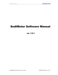
3.2.1
Decoding scheme for accesses to the local MAIN memory from
the VMEbus side
VME Page Decoding:
VME Address line
A31 A30 A29 A28
-
- P31 P30 P29 P28
VMEPAGE Register Bits
Address Interval Decoding:
VME Address line
A27 A26 A25 A24 A23 A22 A21 A20 A19 A18 A17 A16 A15 A14 A13 A12
T27 T26 T25 T24 T23 T22 T21 T20 T19 T18 T17 T16 T15 T14 T13 T12
TOPPAGEU
TOPPAGEL
B27 B26 B25 B24 B23 B22 B21 B20 B19 B18 B17 B16 B15 B14 B13 B12
BOTTOMPAGEU
BOTTOMPAGEL
3-3
THE VME INTERFACE
3.2.2
VME Page Decoding
The access page to the local MAIN memory from VMEbus side is a
256 MByte page, specified by the VMEPAGE register of the gate
array.
The four register bits P31..P28 are compared with the VME
address lines A31..A28, in this order. They define the highest
nibble of the 32 bit VMEbus access address.
3.2.2.1
Register
VMEPAGE
Register
Mnemonic
Address
R/W
Default
VME PAGE register
VMEPAGE
$FFD00200
R/W
$00
Format of VMEPAGE
7
6
5
4
3
2
1
0
-
-
-
-
P31
P30
P29
P28
3..0
P[31..28] -
This bitfield selects the page in
which the local main ram can
accessed from the VME side.
3-4
be
THE VME INTERFACE
3.2.3
VME Interval Decoding
The following registers define the decoding interval for VME
accesses to the local MAIN memory.
3.2.3.1 Registers for Bottom and Top page selection
Register
Bottom
Bottom
Top
Top
Page
Page
Page
Page
Register
Register
Register
Register
U
L
U
L
Mnemonic
Address
R/W
Default
BOTTOMPAGEU
BOTTOMPAGEL
TOPPAGEU
TOPPAGEL
$FFD002D0
$FFD002D4
$FFD002D8
$FFD002DC
R/W
R/W
R/W
R/W
$00
$00
$00
$00
The interval decoding of the access range is accomplished by
two page decoders. One page decoder selects the BOTTOM page and
the other the TOP page of the address interval.
Between these pages all VME addresses are valid.
Each page decoder compares 16 address lines (A27..A11) of the
VMEbus with the contents of two 8-bit registers.
The bottom page decoder compares the address lines A27..A20
with the BOTTOMPAGEU register and the address lines A19..A12
with the BOTTOMPAGEL register.
Likewise, the top page decoder compares the VME address lines
A27..A20 and A19..A12 with the registers TOPPAGEU and TOPPAGEL
respectively.
Each register set (bottom or top) specifies the base address of
its respective 4 KByte page.
The register contents of the top page do not define the end
address of an interval, but specify the base address of its top
page.
The address interval, selected by these registers, ranges from
the base address of the bottom page to the end address of the
top page.
3-5
THE VME INTERFACE
Format of BOTTOMPAGEU
7
6
5
4
3
2
1
0
B27
B26
B25
B24
B23
B22
B21
B20
7..0
B[27..20] These bits are compared with the VMEbus
address lines A27..A20 and select the upper
portion of the bottom page address.
Format of BOTTOMPAGEL
7
6
5
4
3
2
1
0
B19
B18
B17
B16
B15
B14
B13
B12
7..0
B[19..12] These bits are compared with the VMEbus
address lines A19..A12 and select the lower
portion of the bottom page address.
Format of TOPPAGEU
7
6
5
4
3
2
1
0
T27
T26
T25
T24
T23
T22
T21
T20
7..0
T[27..20] These bits are compared with the VMEbus
address lines A27..A20 and select the upper
portion of the top page address.
Format of TOPPAGEL
7
6
5
4
3
2
1
0
T19
T18
T17
T16
T15
T14
T13
T12
7..0
B[27..20] These bits are compared with the VMEbus
address lines A27..A20 and select the lower
portion of the top page address.
3-6
THE VME INTERFACE
3.2.4
Enable Address Modifier Decoding
The address modifier code, which the VME master has to
broadcast for a valid access to the main memory, is selectable
in the ENAMCODE register.
After reset, no access to the main memory from VME side is
possible since the register is cleared and all address modifier
code selections are disabled.
Additionally, the decoding area can be protected from write
accesses by VMEbus masters.
3-7
THE VME INTERFACE
3.2.4.1
Register ENAMCODE
Register
Mnemonic
Enable AM code Register ENAMCODE
Address
R/W
Default
$FFD002B4
R/W
$00
Format of ENAMCODE
7
6
XSP
7..6
XSP -
XSD -
00
01
10
11
2
1
XUP
0
XUD
Extended Supervisor Program Access AM code
Extended Supervisor Data Access AM code
disabled
disabled
enabled for READ-Access
enabled for R/W -Access
XUP -
00
01
10
11
1..0
3
disabled
disabled
enabled for READ-Access
enabled for R/W -Access
00
01
10
11
3..2
4
XSD
00
01
10
11
5..4
5
Extended User Program Access AM code
disabled
disabled
enabled for READ-Access
enabled for R/W -Access
XUD -
Extended User Data Access AM code
disabled
disabled
enabled for READ-Access
enabled for R/W -Access
3-8
THE VME INTERFACE
3.3
Shared Memory Structure Support
When the gate array is initialized to support the shared memory
structure ( selected in the SPECIAL register bit 5), an access
from VME to the local MAIN memory causes the gate array to
request control of the local bus from the processor.
Depending on the selection for RMW cycle support (CTL15
register/"SHAREDRMW" bit), the gate array either performs a
fast execution of the memory access cycle or the memory cycle
is terminated only on completion of the VMEbus cycle.
In the fast execution mode, the gate array first finishes the
memory cycle and then completes the VME cycle.
A memory read cycle is terminated by the gate array after the
data has been latched. A memory write cycle is finished after
the data is stored in the memory.
The local bus is released immediately after the cycle is
terminated.
If the gate array is programmed to support RMW cycles from the
VMEbus (SHAREDRMW bit = 1), the slow access mode to the memory
is selected.
In this mode, the local memory cycle is not terminated until
the VME cycle is finished by a negated VME address strobe. In
this mode, the local bus will be occupied about twice as long
as is the case in the fast access mode.
The gate array terminates a VMEbus access to the local main
memory with VMEbus error, if a parity error is decoded by the
gate array.
This feature is available, if the gate array is configured for
the shared memory structure (defined in the SPECIAL register)
and any option for parity error support by the gate array is
enabled.
3-9
THE VME INTERFACE
3.3.1
RMW Cycles from VME to the MAIN Memory
When the gate array is initialized to support the Shared memory
structure (selected in the SPECIAL register bit 5), readmodify-write cycles from VME can be performed only if the
SHAREDRMW bit enables this type of access.
In this mode, the local bus is kept for the VME master until
the RMW operation is finished.
With the SHAREDRMW option disabled, a correct RMW operation
cannot be guaranteed since the local bus will always be
released for the processor between two consecutive accesses
from VME to the main memory.
Note:
If this option is enabled, not only read-modify-write
cycles from VME to the shared main memory, but also
standard cycles cause the gate array to keep the local
bus mastership for the VME master, until the VME address
strobe is negated to finish the cycle. This will reduce
performance of the local processor!
3.3.1.1
Register
CTL15
Register
Mnemonic
Address
R/W
Default
Control 15 Register
CTL15
$FFD00358
R/W
$00
Format of CTL15
7
6
VSBSEC
TIMEOUT
0
1
0
5
4
BURST
TRANS
BURST
CYCLE
SHAREDRMW -
3
CINH
OFFBRD
2
CINH16
1
CINH
LIO
0
SHARED
RMW
The bit selects if read modify write
cycles from VME to the shared RAM will
be supported by the gate array.
supports RMW cycles
no support for RMW cycles
3-10
THE VME INTERFACE
3.4
VME Access to FGA-002 functions
The gate array provides several functions which are available
from the VMEbus side.
The following functions and status reports, provided by the
gate array, are accessible:
- MAILBOX Locations
- RESET Call function
- STATUS report of the SYSFAIL output signal and the
processor HALT signal line.
The gate array is accessible by all VMEbus masters, which have
short addressing capability (A16). Additionally, the bus master
has to present an address modifier code for the Short I/O
decoding range.
Before a VMEbus master can perform a valid access to the gate
array, two registers have to be initialized by the local
processor.
One register defines the VME page and another selects the code
for the Address Modifier signals which the VME master has to
broadcast for a valid access to the gate array. If no selection
for the address modifier code is made, an access to these gate
array functions from VME side is not possible.
The VME page of the gate array is a 256 byte page which is
decoded by the VME address signals A15..A8. within the short
addressing range of the VMEbus.
Within the VME page, the
functions are assigned fixed offsets.
The VME page is programmable in the register "MYVMEPAGE".
The Address Modifier Code selection is to be made in the "CTL5"
register. The bitfield
"MYAMCODE" selects the valid VME
Address Modifier Code or disables the page decoding.
The function of the mailboxes together with their access
addresses, is described in the section MAILBOXES.
A description of the RESET call, together with its location,
can be found in the section MISCELLANEOUS.
3-11
THE VME INTERFACE
For the status readout of the SFAILO output signal and the HALT
signal the address location
$XXFD
is provided. The status of the SFAILO signal is displayed at
data bit 6 and the HALT signal at data bit 5. The HALT signal
is driven by the 68020 processor to indicate that it stopped
processing. Therefore the HALT signal can only be evaluated
when the 68020 processor is implemented as the local CPU (the
68030 processor does not have a HALT output signal).
No care
has to be taken on the other data bits.
3.4.1
VME page selection
The register "MYVMEPAGE" is used to select the VME page, in
which the gate array can be accessed from VME side.
A valid decoding page can be selected by writing the upper byte
($UU) of a short address ($UUXX) into the 8 bit register.
This register holds the bits Y15..Y08, which are compared with
the VMEbus address lines A15..A08. The decoding is valid when
the register bit pattern matches the corresponding VME address
signals.
3.4.1.1
Register
MYVMEPAGE
Register
Mnemonic
Address
R/W
Default
FGA-002 VME Page
MYVMEPAGE
$FFD002FC
R/W
$00
Format of MYVMEPAGE
7
6
5
4
3
2
1
0
Y15
Y14
Y13
Y12
Y11
Y10
Y09
Y08
7..0
Y15..Y08 -
These bits select the VME page for
accesses from the VMEbus to the gate
array functions. The bits are compared
with the VME address signals A15..A08.
3-12
THE VME INTERFACE
3.4.2
Address Modifier Code selection
The Control Register 5 (CTL5) provides two bits to select the
address modifier code, which has to be broadcast by the bus master
for a valid access to the gate array.
If the bits are zero, which is the case after reset, no VME access
to the gate array is possible.
3.4.2.1
Register
CTL5
Register
Mnemonic
Address
R/W
Default
Control 5 Register
CTL5
$FFD00264
R/W
$00
Format of CTL5
7
6
5
4
-
-
-
-
3..2
00
01
10
11
MYAMCODE -
3
2
MYAMCODE
1
0
AUXOPTB AUXOPTA
This bitfield selects the AM-Code
for VME accesses to the gate array.
=
=
=
=
VME page decoding disabled
Short Non-Privileged AM code $29
Short Supervisory AM code $2D
Both Short AM-Codes allowed
3-13
INTERRUPT MANAGEMENT
INTERRUPT MANAGEMENT
This page was intentionally left blank
INTERRUPT MANAGEMENT
TABLE OF CONTENTS
1.
GENERAL DESCRIPTION
. . . . . . . . . . . . . . . . .
2.
OPERATION DESCRIPTION . . . . . . . . . . . . . . . .
2.1 INTERRUPT REQUEST
. . . . . . . . . . . . . . .
2.1.1
Internal Interrupt Sources
. . .
2.1.1.1
DMA CONTROLLER
. . . .
2.1.1.2
TIMER . . . . . . . . .
2.1.1.3
FORCE MESSAGE BROADCAST FMB. . . . . . . . .
2.1.1.4
PARITY ERROR
. . . . .
2.1.1.5
MAILBOXES . . . . . . .
2.1.2
External Interrupt Sources
. . .
2.1.2.1
LOCAL INTERRUPTS
. . .
2.1.2.2
UTILITY INTERRUPTS
. .
2.1.2.3
VME INTERRUPTS
. . . .
2.2 INTERRUPT ACKNOWLEDGE
. . . . . . . . . . . . .
2.2.1
Internal Vector Response
. . . .
2.2.2
Local I/O Vector Response or Internal
Vector Response
. . . . . . . . . . . . . .
2.2.2.1
Local IACK control register
LOCALIACK
. . . . . . . . . . . . .
2.2.3
VMEbus Vector Response
. . . . .
2.2.4
EMPTY Vector Response . . . . . .
2.3 Interrupt Priority Structure . . . . . . . . . .
2.4 Interrupt Vector Page
. . . . . . . . . . . . .
2.4.1
Interrupt Vector Page Programming
2.4.2
Register CTL3 . . . . . . . . . .
2.5 Interrupt Registers
. . . . . . . . . . . . . .
2.5.1
Register Map of INTERRUPT CONTROL and
STATUS REGISTER
. . . . . . . . . . . . . .
2.5.2
The Interrupt Control Register
.
2.5.3
Interrupt Status Register . . . .
1-1
2-1
2-1
2-2
2-3
2-3
2-3
2-4
2-4
2-5
2-6
2-6
2-7
2-8
2-8
2-10
2-12
2-12
2-13
2-14
2-15
2-18
2-18
2-19
2-19
2-20
2-24
INTERRUPT MANAGEMENT
This page was intentionally left blank
INTERRUPT MANAGEMENT
1.
GENERAL DESCRIPTION
The FGA-002 Gate Array provides high end support for interrupt
functionality.
It manages interrupt sources within the gate array as well as
external sources connected to the gate array.
The FGA-002 Gate Array is an efficient interface for various
interrupt sources to the local CPU, and supports up to 18 external
interrupters.
Interrupt inputs provided for external interrupt sources (exclusive
of the VMEbus interrupt inputs) offer maximum flexibility as they may
be configured to be level/edge sensitive or low/high active.
The control of these features is performed by two bits contained in
the extended interrupt control registers. The Interrupt Auto Clear
bit in the extended interrupt control register determines, whether
the interrupt of an edge sensitive input is cleared automatically
during the interrupt acknowledge cycle or has to be cleared by the
interrupt service routine.
Each interrupt source is bound to an individual interrupt channel
which has its own assigned vector number.
The interrupt channels are configured by the Interrupt Control
Registers where a 3 bit code for the level and a bit for
enable/disable control are stored. Each interrupt channel may be
programmed to interrupt the processor at any level.
The vector table of the gate array is a group of 64 vectors. The two
most significant bits of the 8 bit vector are programmable via
register bits.
The rest of the bits are assigned by gate array hardware. Not all of
the 64 vectors are used in the present gate array, and those not used
are reserved for future extensions.
1-1
INTERRUPT MANAGEMENT
The following groups of interrupt sources are supported:
1.
Internal Interrupt Sources
-
2.
DMA CONTROLLER
TIMER
FORCE MESSAGE BROADCAST -FMBPARITY ERROR
8 MAILBOXES
External Interrupt Sources
Onboard interrupts:
-
LOCAL 0-7 inputs
ABORT Key input
ACFAIL input
SYSFAIL input
VMEbus interrupts:
- 7 VMEbus interrupt inputs
1-2
INTERRUPT MANAGEMENT
2.
DESCRIPTION OF OPERATION
2.1
INTERRUPT REQUEST
The FGA-002 Gate Array requests service from the processor when the
interrupt channel recognizes the interrupt of an external or internal
source.
A pending interrupt from an interrupt source will be recognized when
the IRQ enable bit in the interrupt control register is set to 1. An
interrupt level greater than 0 has to be programmed in order that the
gate array sends the interrupt request to the processor.
The gate array supports seven interrupt levels for service requests
to the local CPU. Each interrupt can be converted to any of the seven
interrupt levels by programming the lower three bits of the interrupt
control register, which stores the interrupt request level code.
2-1
INTERRUPT MANAGEMENT
2.1.1
Internal Interrupt Sources
The following table shows the FGA-002 Gate Array internal interrupt
sources and their assigned interrupt channels:
Interrupt Source
Interrupt Channel
DMA CONTROLLER:
Normal Termination Interrupt
Error Termination Interrupt
DMA Normal
DMA Error
TIMER:
Timer Interrupt:
Timer
FORCE MESSAGE BROADCAST:
Channel0 Message Interrupt
Channel1 Message Interrupt
Channel0 Refused Interrupt
Channel1 Refused Interrupt
FMB0
FMB1
FMB0
FMB1
PARITY ERROR:
Parity Error Interrupt:
PARITY Error
MAILBOXES:
Mailbox 0 Interrupt
Mailbox 1 Interrupt
Mailbox 2 Interrupt
Mailbox 3 Interrupt
Mailbox 4 Interrupt
Mailbox 5 Interrupt
Mailbox 6 Interrupt
Mailbox 7 Interrupt
Mailbox
Mailbox
Mailbox
Mailbox
Mailbox
Mailbox
Mailbox
Mailbox
2-2
Message
Message
Refused
Refused
0
1
2
3
4
5
6
7
INTERRUPT MANAGEMENT
2.1.1.1
DMA CONTROLLER
Two interrupts are assigned to the DMA controller:
Normal termination interrupt
Error termination interrupt
The DMA controller generates a normal termination interrupt request
if its task is successfully terminated.
An error termination interrupt occurs if the DMA operation is aborted
by a stop command. The stop command is issued if bit 0 in the
DMARUNCTL register is written with 0.
Also the DMA operation is forced to stop when a bus error condition
occurs.
The active interrupt state is when bit 7 in the Interrupt status
registers ISDMANORM and ISDMAERR is zero.
The interrupts can be cleared by writing the corresponding status
register with any data.
2.1.1.2
TIMER
The timer triggers its interrupt request when the counter decrements
from $01 to $00.
A pending interrupt request is displayed as a low in bit 7 of the
timer interrupt status register.
Writing the timer interrupt status register clears the interrupt. The
written data will be ignored.
After reset the timer interrupt is cleared.
2.1.1.3
FORCE MESSAGE BROADCAST -FMB-
The gate array contains two FMB message channels to receive messages
from the VMEbus.
Each FMB message channel can generate the "message" interrupt request
and the "refused" interrupt request.
The message interrupt request is pending as long as there are
messages contained in the message fifo. After the last message has
been read by the local CPU, the message interrupt request disappears.
An active message interrupt request is displayed in the interrupt
status register bit 7. The bit is low if the interrupt is asserted.
2-3
INTERRUPT MANAGEMENT
The refused interrupt request is edge triggered and can be cleared by
a write cycle to the corresponding interrupt status register. The
status register displays 1 at bit 7 if the refused interrupt is
pending.
2.1.1.4
PARITY ERROR
If one of the parity error options is enabled, an interrupt request
is triggered when the gate array internal parity checkers detect a
parity error.
A pending interrupt is displayed in the parity error status register.
Bit 7 returns zero if the interrupt request is asserted.
The interrupt is cleared through a write cycle to the status register
location.
2.1.1.5
MAILBOXES
A mailbox interrupt request is active when a read access to the
mailbox location in the FGA-002 gate array is performed.
The mailbox interrupt is pending until a write access to the same
mailbox location will clear the interrupt.
The read/write accesses can be performed not only from VME side but
also from the local processor.
For details please refer to the section entitled "THE MAILBOXES".
2-4
INTERRUPT MANAGEMENT
2.1.2
External Interrupt Sources
The FGA-002 gate array contains 18 interrupt request inputs to
provide for external interrupt sources. The inputs are assigned to
the interrupt channels as shown in the following table:
Interrupt Source
Interrupt Channel
LOCAL
LIRQ0
LIRQ1
LIRQ2
LIRQ3
LIRQ4
LIRQ5
LIRQ6
LIRQ7
LOCAL0
LOCAL1
LOCAL2
LOCAL3
LOCAL4
LOCAL5
LOCAL6
LOCAL7
INTERRUPTS:
input pin
input pin
input pin
input pin
input pin
input pin
input pin
input pin
UTILITY INTERRUPTS:
ABOKEY input pin
ACFAIL input pin
SFAILI input pin
ABORT
ACFAIL
SYSFAIL
VME INTERRUPTS:
VIRQ7 input pin
VIRQ6 input pin
VIRQ5 input pin
VIRQ4 input pin
VIRQ3 input pin
VIRQ2 input pin
VIRQ1 input pin
VIRQ7*
VIRQ6*
VIRQ5*
VIRQ4*
VIRQ3*
VIRQ2*
VIRQ1*
2-5
INTERRUPT MANAGEMENT
2.1.2.1
LOCAL INTERRUPTS
The LOCAL 0-7 interrupt inputs may be configured to be high or low
active and edge or level sensitive.
The configuration is to be
selected in the corresponding Extended Interrupt Control Register.
Edge sensitive configured LOCAL interrupt inputs trigger an interrupt
on the active edge of the input signal. Active low
inputs trigger the interrupt on the high-to-low edge and active high
inputs on the low-to high edge.
A pending interrupt request of a LOCAL interrupt input is readable on
the respective status register location.
Reading bit 7 of the interrupt status register returns the active
state of the interrupt request.
The bit is low if the interrupt is pending and high when no interrupt
is pending, independent of the selected input activity.
The interrupt of edge sensitive configured inputs can be cleared
either with a write access to the interrupt status register location
or automatically when the processor executes the interrupt
acknowledge cycle. For this mode, the autoclear option has to be
enabled in the extended interrupt control register.
The clear operation of the interrupt request with a write access to
the interrupt status register can be accomplished with any data.
2.1.2.2
UTILITY INTERRUPTS
The utility interrupt inputs for ABORT, ACFAIL and SYSFAIL can be
configured like the local interrupt inputs as edge/level sensitive
and high/low active inputs. The configuration has to be programmed in
the corresponding extended interrupt control register.
When a utility interrupt input is configured edge sensitive, the
status of a pending interrupt can be read at the location of the
interrupt status register (bit 7).
The status bit indicates low if the interrupt is pending and high
when no interrupt is pending.
2-6
INTERRUPT MANAGEMENT
Edge sensitive utility interrupts can be cleared by a write access
(data is ignored) to the respective status register location or
automatically in the acknowledge cycle if the autoclear option is
enabled (see extended interrupt control register).
The active state of level sensitive ABORT, ACFAIL and SYSFAIL
interrupt inputs can be identified by reading back the instantaneous
level of the respective input pin.
The level is read back at bit 7 of the following registers locations:
Register
Address
ABORTPIN
ACFAILPIN
SFAILINPIN
$FFD004D4
$FFD004D8
$FFD004DC
2.1.2.3
VME INTERRUPTS
The inputs provided for VMEbus interrupt requests are level sensitive
inputs. The interrupt is active when the input signal is asserted
low.
The VMEbus interrupt channels have no associated interrupt status
registers.
As in the case for all other interrupt sources the gate array can map
the VMEbus interrupts to any interrupt level for the CPU.
2-7
INTERRUPT MANAGEMENT
2.2
INTERRUPT ACKNOWLEDGE
The FGA-002 gate array decodes interrupt acknowledge cycles from the
processor and responds to the cycle by presenting an interrupt vector
on the data pins DCPU31-DCPU24. The vector which is presented to the
processor may be supplied by the gate array internal interrupt logic
or by the external interrupter.
External Vector response is supported for the VMEbus interrupts and
for the local interrupts LOCAL4-LOCAL7.
The vector which is supplied by an external interrupter is
transmitted by the gate array from the LOCAL I/O bus or the VMEbus to
the CPU data bus.
VMEbus interrupts are supported as external vector responses.
The gate array requires the interrupt vector to be presented at the
data pins DVME0-DVME7 of the gate array. After being read in, the
vector is presented to the CPU data pins DCPU24-DCPU31.
2.2.1
Internal Vector Response
When the gate array responds to an interrupt acknowledge cycle with
an Internal Vector, it places the vector number of the acknowledged
interrupt channel on the CPU data pins
DCPU24 - DCPU29. To complete the 8 bit vector information, the two
uppermost vector bits determining the Interrupt Vector Page are
provided by the CTL3 register and are driven on the DCPU30 - DCPU31
pins.
2-8
INTERRUPT MANAGEMENT
The gate array supports interrupt acknowledge cycles with the
internal vector number when the following interrupt channels are
decoded:
INTERRUPT CHANNEL
VECTOR NUMBER
Mailbox 0
Mailbox 1
Mailbox 2
Mailbox 3
Mailbox 4
Mailbox 5
Mailbox 6
Mailbox 7
Timer
FMB1 Refused
FMB0 Refused
FMB1 Message
FMB0 Message
ABORT
ACFAIL*
SYSFAIL*
DMA Error
DMA Normal
PARITY Error
LOCAL0
LOCAL1
LOCAL2
LOCAL3
$00
$01
$02
$03
$04
$05
$06
$07
$20
$24
$25
$26
$27
$28
$29
$2A
$2B
$2C
$2D
$30
$31
$32
$33
Empty Interrupt
$3F
2-9
INTERRUPT MANAGEMENT
2.2.2
Local I/O Vector Response or Internal Vector Response
The LOCAL4 - LOCAL7 interrupts are supported by three different modes
of response to an interrupt acknowledge cycle of the processor.
The modes are:
1.
2.
3.
Response with Internal Vector Number
Response with External Interrupt Vector
No response
The modes are selected in the control register LOCALIACK.
The register also controls the timing of the access on the LOCAL I/O
bus which fetches the vector from the interrupting device.
The contents of this register have to be programmed according to the
external hardware configuration.
INTERRUPT CHANNEL
VECTOR NUMBER
LOCAL4
LOCAL5
LOCAL6
LOCAL7
$34
$35
$36
$37
or
or
or
or
from
from
from
from
Local
Local
Local
Local
I/O
I/O
I/O
I/O
bus
bus
bus
bus
When internal vector response is selected, the associated vector
number of the acknowledged interrupt channel is presented to the
processor.
For external vector response, the gate array fetches the interrupt
vector on the Local I/O bus and transmits it to the CPU data bus. In
this case, the external device connected to the Local I/O data bus of
the gate array has to provide the interrupt vector.
The third selection is that the gate array does not respond to the
IACK cycle of the processor. This mode supports interrupting devices
which are directly connected to the CPU data bus.
External interrupters connected to the LOCAL4 - LOCAL7 interrupt
channels are supported by the gate array’s four acknowledge outputs
LIACK 4-7, respectively. A LIACKx output will be asserted low when
the processor acknowledges the corresponding LOCALx interrupt.
2-10
INTERRUPT MANAGEMENT
2.2.2.1
Local IACK control register LOCALIACK
The 8 bit control register LOCALIACK is assigned to the LOCAL
4-7 interrupts and selects the internal or external vector
response mode for these interrupts.
Also selectable by the LOCALIACK control register is the access
time to the LOCAL I/O bus in an interrupt acknowledge cycle
when the external response mode is needed.
The register is grouped into four bit fields where each field
stores a 2 bit code to control the vector response mode of one
of the LOCAL 4-7 interrupts.
Register
Mnemonic
Local IACK Control Reg. LOCALIACK
Address
R/W
Default
$FFD00334
R/W
$00
Format of LOCALIACK
7
6
LOCAL7
5
4
3
LOCAL6
2
LOCAL5
1
0
LOCAL4
7..6
LOCAL7
This bit field controls the vector
response mode of the gate array for the
LOCAL 7 interrupt.
5..4
LOCAL6
This bit field controls the vector
response mode of the gate array for the
LOCAL 6 interrupt channel.
3..2
LOCAL5
This bit field controls the vector
response mode of the gate array for the
LOCAL 5 interrupt.
1..0
LOCAL4
This bit field controls the vector
response mode of the gate array for the
LOCAL 4 interrupt.
2-11
INTERRUPT MANAGEMENT
The 2 bit code stored in the LOCALIACK register for the control
of the vector response mode of the LOCAL 4-7 interrupts has the
following selections:
00 =
The gate array answers with an internal vector.
The vector of the corresponding LOCAL interrupt is
driven on the CPU data bus signals DCPU31..DCPU24.
The corresponding LIACKx pin will be asserted.
01 =
During the processor’s IACK cycle the gate array
does not intervene but merely asserts the
corresponding LIACK pin as soon as possible.
10 =
Upon IACK, the gate array responds to the CPU with
an external vector. The corresponding LIACKx
signal will be asserted and the interrupting
device has to supply the interrupt vector. The
vector is read on the local I/O bus and presented
on the CPU data bus. The access time to the
interrupting device on the local I/O bus is 1 us.
11 =
Upon IACK, the gate array responds to the CPU with
an external vector. The corresponding LIACKx pin
will be asserted and the interrupting device has
to supply the interrupt vector. The vector is read
on the local I/O bus and presented on the CPU data
bus. The access time to the interrupting device on
the local I/O bus is 500ns.
2.2.3
VMEbus Vector Response
VMEbus interrupts are handled
external vector response.
by
the
gate
array
with
an
If a VMEbus interrupt is serviced by the processor, the FGA-002
gate array awaits vector data delivered by the VMEbus
interrupter on data pins DVME0-DVME7.
The vector will be read in and transmitted to the CPU data pins
DCPU24-DCPU31.
2-12
INTERRUPT MANAGEMENT
INTERRUPT CHANNEL
VIRQ7*
VIRQ6*
VIRQ5*
VIRQ4*
VIRQ3*
VIRQ2*
VIRQ1*
2.2.4
VECTOR NUMBER
external
external
external
external
external
external
external
from
from
from
from
from
from
from
VME
VME
VME
VME
VME
VME
VME
EMPTY Vector Response
The gate array responds to the IACK cycle of the CPU by
presenting an interrupt vector. This is normally the interrupt
channel vector which is decoded by the gate array interrupt
logic or the external vector supplied by the interrupting
device.
In order to guarantee that the interrupt channel which is
addressed by the processor in the IACK cycle is decoded
successfully by the gate array, the interrupt source must hold
the request stable in the asserted state.
Care has been taken with the design of the gate array interrupt
circuitry to prevent the IACK cycle from being terminated with
a timeout bus error if a decoding fault occurs.
However, if an interrupt source could not be decoded in an IACK
cycle, the gate array always supplies the EMPTY interrupt
vector to the processor.
The EMPTY interrupt vector is assigned to the EMPTY interrupt
channel and carries the vector number $3F.
The EMPTY interrupt channel is a virtual channel which means
that there is no interrupt source to trigger this interrupt.
Accordingly it does not own an interrupt control register or an
interrupt status register.
2-13
INTERRUPT MANAGEMENT
2.3
Interrupt Priority Structure
The FGA-002 Gate Array interrupt management provides a software
controllable method of prioritization for the interrupts using
programmable interrupt levels.
Seven different interrupt levels are supported by the interrupt
management. Highest priority is given to level 7 and lowest
priority to level 1.
Each level is coded so that the interrupt priority level
signals (IPL2 - IPL0) of the 68020/68030 processor can be
directly connected to the FGA-002 Gate Array.
If the interrupt request level is programmed to zero, no
interrupt will be sent to the processor. This is similar to the
interrupt being disabled by clearing the enable bit in the
corresponding interrupt control register.
A second kind of prioritization is hardware defined inside the
gate array and is designated as the interrupt daisy chain. The
interrupt daisy chain structure defines the order in which
interrupts on the same level will be serviced. The daisy chain
operates such that interrupt priority decreases with ascending
vector numbers.
The main priority is always determined by the interrupt level.
This means that prioritization according to the interrupt daisy
chain is only given for interrupt sources which are programmed
on the same interrupt level.
Therefore, an interrupt source programmed to interrupt level 6
always has priority over a level 5 interrupt, although its
channel may be after the other channel in the daisy chain.
The order of the interrupt daisy chain is given in Table 2-1
"Interrupt Vector Number Assignment".
2-14
INTERRUPT MANAGEMENT
2.4
Interrupt Vector Page
The 8 bit interrupt vector information, which is presented by
the gate array when it responds to IACK cycles with an internal
vector, is set together from the lower 6 bit field for the
vector number and the upper 2 bit field for the vector page.
The lower six bits are provided by the prioritization logic and
determine the vector number of the corresponding interrupt
channel.
The upper two bits are programmable in the CTL3
register and are common for all vector numbers of the gate
array.
For details please refer to "Interrupt Vector Page Programming"
later in this description.
The interrupt vector table of the FGA-002 Gate Array consists
of a contiguous block of 64 vector numbers.
Unused vector number entries are reserved for future
extensions.
NOTE:
The zero vector page (the two most significant
bits of the interrupt vector are 0) is a reserved
area for system vectors of 68020/68030 processors.
Since all bits of the CTL3 register are set to
zero after reset, the default gate array vector
page is the zero page. Therefore the bootup
software has to initialize this register to select
one of the remaining vector pages.
The vector page (binary "11XXXXXX") generating the interrupt
vectors $C0 - $FF is used by FORCE bootup software and reserved
for future interrupt enhancement.
The following table shows the interrupt channels and the
assigned vector numbers:
2-15
INTERRUPT MANAGEMENT
Table 2-1:
Interrupt Vector Number Assignment
INTERRUPT CHANNEL
VECTOR NUMBER
DAISY CHAIN
Mailbox
Mailbox
Mailbox
Mailbox
Mailbox
Mailbox
Mailbox
Mailbox
$00
$01
$02
$03
$04
$05
$06
$07
highest
priority
reserved
:
reserved
$08
:
$1F
descending
priority
Timer
reserved
reserved
reserved
FMB1 Refused
FMB0 Refused
FMB1 Message
FMB0 Message
$20
$21
$22
$23
$24
$25
$26
$27
\/
ABORT
ACFAIL*
SYSFAIL*
DMA Error
DMA Normal
PARITY Error
reserved
reserved
$28
$29
$2A
$2B
$2C
$2D
$2E
$2F
LOCAL0
LOCAL1
LOCAL2
LOCAL3
LOCAL4
LOCAL5
LOCAL6
LOCAL7
$30
$31
$32
$33
$34
$35
$36
$37
reserved
reserved
reserved
reserved
reserved
reserved
reserved
$38
$39
$3A
$3B
$3C
$3D
$3E
0
1
2
3
4
5
6
7
2-16
or
or
or
or
external
external
external
external
INTERRUPT MANAGEMENT
Table 2-1: Interrupt Vector Number Assignment(cont’d)
INTERRUPT CHANNEL
VECTOR NUMBER
VIRQ7*
VIRQ6*
VIRQ5*
VIRQ4*
VIRQ3*
VIRQ2*
VIRQ1*
external
external
external
external
external
external
external
Empty Interrupt
$3F
2-17
from
from
from
from
from
from
from
DAISY CHAIN
VME
VME
VME
VME
VME
VME
VME
descending
priority
\/
lowest
priority
INTERRUPT MANAGEMENT
2.4.1
Interrupt Vector Page Programming
The interrupt vector page is to be programmed in the Control
Register 3 (CTL3). A two bit field of this register defines
the common most significant bits of the internal interrupt
vectors supplied by the FGA-002 gate array. Register bit 3 is
used as vector bit 7, register bit 2 as vector bit 6.
The bits 1 and 0 of the CTL3 register are used to control other
internal functions. Therefore, the register bits 1 and 0 must
retain their value when the contents of the vector bits are
altered.
Register
Mnemonic
Address
R/W
Default
Control Register 3
CTL3
$FFD00250
R/W
$00
2.4.2
Register CTL3
7
6
5
4
3
2
1
0
-
-
-
-
VECTOR
BIT 7
VECTOR
BIT 6
VSBENA
OPT16
" - " Denotes nonexistent bits.
3..2
VECTORBIT [7..6]
The two bit field defines the
uppermost bits of the interrupt vector which is supplied
by the gate array when it
responds to IACK cycles with
an internal vector number.
2-18
INTERRUPT MANAGEMENT
2.5
Interrupt Registers
2.5.1
Register Map of INTERRUPT CONTROL and STATUS REGISTER
The following chart displays the register map for the interrupt
control and status register.
INTERRUPT
CHANNEL
CONTROL REGISTER
STATUS REGISTER
Mnemonic
Address
ICRMBOX0
ICRMBOX1
ICRMBOX2
ICRMBOX3
ICRMBOX4
ICRMBOX5
ICRMBOX6
ICRMBOX7
$FFD00000
$FFD00004
$FFD00008
$FFD0000C
$FFD00010
$FFD00014
$FFD00018
$FFD0001C
-
Timer
ICRTIM0
$FFD00220
ISTIM0
$FFD004A0
FMB1
FMB0
FMB1
FMB0
ICRFMB1REF
ICRFMB0REF
ICRFMB1MES
ICRFMB0MES
$FFD00244
$FFD00240
$FFD0024C
$FFD00248
ISFMB1REF
ISFMB0REF
ISFMB1MES
ISFMB0MES
$FFD004BC
$FFD004B8
$FFD004E4
$FFD004E0
ABORT
ACFAIL*
SYSFAIL*
ICRABORT
ICRACFAIL
ICRSYSFAIL
$FFD00280
$FFD00284
$FFD00288
ISABORT
ISACFAIL
ISSYSFAIL
$FFD004C8
$FFD004CC
$FFD004D0
DMA Error
DMA Normal
ICRDMAERR
ICRDMANORM
$FFD00234
$FFD00230
ISDMAERR
ISDMANORM
$FFD004B4
$FFD004B0
PARITY Error
ICRPARITY
$FFD00258
ISPARITY
$FFD004C0
LOCAL0
LOCAL1
LOCAL2
LOCAL3
LOCAL4
LOCAL5
LOCAL6
LOCAL7
ICRLOCAL0
ICRLOCAL1
ICRLOCAL2
ICRLOCAL3
ICRLOCAL4
ICRLOCAL5
ICRLOCAL6
ICRLOCAL7
$FFD0028C
$FFD00290
$FFD00294
$FFD00298
$FFD0029C
$FFD002A0
$FFD002A4
$FFD002A8
ISLOCAL0
ISLOCAL1
ISLOCAL2
ISLOCAL3
ISLOCAL4
ISLOCAL5
ISLOCAL6
ISLOCAL7
$FFD00480
$FFD00484
$FFD00488
$FFD0048C
$FFD00490
$FFD00494
$FFD00498
$FFD0049C
VIRQ7*
VIRQ6*
VIRQ5*
VIRQ4*
VIRQ3*
VIRQ2*
VIRQ1*
ICRVME7
ICRVME6
ICRVME5
ICRVME4
ICRVME3
ICRVME2
ICRVME1
$FFD0021C
$FFD00218
$FFD00214
$FFD00210
$FFD0020C
$FFD00208
$FFD00204
-
Mailbox
Mailbox
Mailbox
Mailbox
Mailbox
Mailbox
Mailbox
Mailbox
0
1
2
3
4
5
6
7
Refused
Refused
Message
Message
2-19
Mnemonic
Address
-
-
INTERRUPT MANAGEMENT
2.5.2
The Interrupt Control Register
There are two different types of interrupt control registers
implemented in the FGA-002 gate array:
1. Standard Interrupt control registers
2. Extended interrupt control registers
Both types of Interrupt Control registers are used to configure
the interrupt channels of the corresponding interrupt source.
They provide selection of the interrupt level generation and
enable/disable control. Extended Interrupt Control Registers
have additional bits to select characteristics of the
corresponding interrupt input.
Extended interrupt control
registers are used to control the LOCAL interrupts as well as
the ABORT-, ACFAIL- and SYSFAIL interrupts. All other interrupt
channels of the gate array are configured by standard interrupt
control registers.
The following chart shows the assignment of control registers
to the corresponding interrupts in detail.
INTERRUPT CONTROL REGISTERS
STANDARD
EXTENDED
Mailbox 0
Mailbox 1
Mailbox 2
Mailbox 3
Mailbox 4
Mailbox 5
Mailbox 6
Mailbox 7
Timer
FMB1 Refuse
FMB0 Refused
FMB1 Message
FMB0 Message
DMA Error
DMA Normal
PARITY Error
VMEbus IRQ7*
VMEbus IRQ6*
VMEbus IRQ5*
VMEbus IRQ4*
VMEbus IRQ3*
VMEbus IRQ2*
VMEbus IRQ1*
LOCAL0
LOCAL1
LOCAL2
LOCAL3
LOCAL4
LOCAL5
LOCAL6
LOCAL7
ABORT
ACFAIL*
SYSFAIL*
2-20
INTERRUPT MANAGEMENT
The standard interrupt control registers contain four register
bits while the extended interrupt control registers contain
seven control bits. Unused register bits have to be programmed
to zero.
Both register types have in common the control function of the
lower four register bits. These bits configure the interrupt
channel. The bits 2-0 store the level code and determine on
which level service is requested from the CPU. Bit 3 enables or
disables the interrupt channel.
Bits 6-4 of the extended interrupt control registers
configure the interrupt input provided for external interrupt
sources and select the autoclear option. Bit 4 enables/
disables the autoclear option while bit 5 selects the activity
of the interrupt input to be high/low active. Bit 6 determines
if the IRQ input is edge or level sensitive.
All interrupt control registers of the FGA-002 Gate Array
are initialized to $00 after reset.
Format of Standard Interrupt Control Register
7
6
5
4
-
-
-
-
3
IRQ
Enable
2
1
0
Interrrupt Level Select
Format of Extended Interrupt Control Register
7
6
-
Edge/
Level
5
Acti
vity
4
3
Auto
clear
IRQ
Enable
2-21
2
1
0
IRQ Level Select
INTERRUPT MANAGEMENT
6
Edge/Level -
Extended interrupt control register
bit.
The bit selects whether the interrupt
input is level or edge sensitive. If
the bit is set to 1, the interrupt
input
is
selected
to
be
edge
sensitive. An active edge at the
interrupt input pin triggers the
interrupt. If the bit is 0, the
interrupt input is level sensitive.
As bit 6 is cleared to zero after
reset, level sensitivity is selected
by default.
1
Interrupt input is edge
0
Interrupt input is level sensitive
5
Activity -
sensitive
Extended Interrupt Control Register
Bit.
This bit configures the interrupt
input to be active high or active
low. An active low input means that
the interrupt will be triggered by a
high-to-low
edge
for
an
edge
sensitive input or a low level on the
interrupt input pin for a level
sensitive input. An active high input
means that the interrupt will be
triggered by a low-to-high edge or a
high level on the interrupt input
pin.
After reset, the bit is cleared and
the input activity is active low!
1
Interrupt input is active high
0
Interrupt input is active low
2-22
INTERRUPT MANAGEMENT
4
Autoclear -
Extended interrupt control register
bit.
If this bit is cleared, an interrupt
acknowledge cycle that answers the
interrupt
will
clear
the
edge
triggered interrupt automatically.
0
Autoclear option is enabled
1
Autoclear option is disabled
3
IRQ Enable -
The bit enables or disables the
interrupt channel. If the bit is 0,
the
interrupt
request
is
not
recognized by the interrupt channel.
1
Interrupt channel is enabled
0
Interrupt channel is disabled
2..0
000
001
010
011
100
101
110
111
IRQ Level -
This bit field defines the interrupt
request level. If no interrupt level
is selected, the interrupt channel is
disabled
No level selected
Level 1
Level 2
Level 3
Level 4
Level 5
Level 6
Level 7
2-23
INTERRUPT MANAGEMENT
2.5.3
Interrupt Status Register
The Interrupt Status Registers contain a single bit position
which reflects whether or not an interrupt is pending. A read
access to the status register bit returns zero if there is an
interrupt pending. A logical one is read when no interrupt is
pending. The status bit is readable at bit 7 of the interrupt
status register.
The status register is always readable and does not effect device
operation.
Format of the Interrupt Status Register
7
6
5
4
3
2
1
0
IRQ
Status
-
-
-
-
-
-
-
7
1
0
IRQ Status
The IRQ Status register bit reflects
whether there is an interrupt request
pending or not.
is returned, if no interrupt is pending
is returned, if an interrupt request is
pending
2-24
THE 32 BIT
DMA CONTROLLER
THE 32 BIT DMA CONTROLLER
This page was intentionally left blank
THE 32 BIT DMA CONTROLLER
TABLE OF CONTENTS
1.
FEATURES
. . . . . . . . . . . . . . . . . . . . .
2.
GENERAL DESCRIPTION
3.
DMA REGISTERS
. . . . . . . . . . . . . . . . . .
3-1
3.1 DMA Controller Register Organization
. . . .
3-1
3.2 DMA Controller Register Address Assignment
. .
3-2
3.3 DMA Controller Register Description . . . . . .
3-3
3.3.1
Source Attribute Register DMASRCATT . .
3-3
3.3.2
Destination Attribute Register DMADSTATT
3-3
3.3.3
General Control Register DMAGENERAL . .
3-5
3.3.4
Run Control Register DMARUNCTL
. . . .
3-6
3.3.5
Mode Status Register DMAMODE
. . . .
3-7
3.3.6
Source Address Register DMASRCADR
. .
3-7
3.3.7
Destination Address Register DMADSTADR
3-7
3.3.8
Transfer Count Register DMATRFCNT
. .
3-8
3.3.9
Interrupt Control Register Normal Termination ICRDMANOR
. . . . . . . . . . . .
3-8
3.3.10 Interrupt Control Register Error Termination ICRDMAERR
. . . . . . . . . . . .
3-9
3.3.11 Interrupt Status Register Normal Termination ISDMANORM
. . . . . . . . . . . 3-10
3.3.12 Interrupt Status Register Error Termination ISDMAERR . . . . . . . . . . . . . 3-10
. . . . . . . . . . . . . . .
1-1
2-1
LIST OF TABLES
Table 3-1: Attribute Code for the Source/Destination Port
3-4
THE 32 BIT DMA CONTROLLER
This page was intentionally left blank
THE 32 BIT DMA CONTROLLER
1.
FEATURES
The FGA-002 Gate Array contains a high speed 32 bit DMA
Controller Module providing the following features:
- 32 bit Addressing Range
- 32 bit Count Register
- Multiport Data Transfer Capability
CPU bus
> CPU bus
> VME bus
> AUX bus
VME bus
> VME bus
> CPU bus
> AUX bus
AUX bus
> CPU bus
> VME bus
- 32 Byte deep internal FIFO
- 32 bit Data Port on Local and VME side
- Up to 25 Mbyte/second transfer rate
- 2 vectored interrupts
- Internal registers allow complete software control by the
local CPU
1-1
THE 32 BIT DMA CONTROLLER
This page was intentionally left blank
1-2
THE 32 BIT DMA CONTROLLER
2.
GENERAL DESCRIPTION
The FGA-002 Gate Array includes a multi-interface 32 bit DMA
Controller Module.
The DMA Controller can be programmed and started from the local
CPU side. The source and destination ports can be selected as
follows:
Port
Device
CPU
CPU
CPU
CPU
MAIN MEMORY
Secondary Bus
Secondary Bus
Secondary Bus
Bus
Bus
Bus
Bus
Data Bus Width
VMEbus
VMEbus
VMEbus
32
32
16
8
bit
bit
bit
bit
32 bit
16 bit
8 bit
AUX Bus
8 bit
The DMA controller reads data from the source port into a 32
byte deep gate array internal FIFO as long as it is requested
to or until the FIFO is full. Data is then transferred from
the internal FIFO to the destination port, until the FIFO is
empty. Then the FIFO is filled again and the process continues
until the transfer is completed.
Source and destination addressing is the full 32 bit address
space and the count register has 32 bits.
The DMA controller can transfer any number of bytes from any
(unaligned) start address to any (unaligned) destination
address.
The DMA controller uses the internal FIFO to minimize the
number of transfer cycles. If unaligned transfers are
necessary, they only occur at the beginning and/or end of the
transfer.
2-1
THE 32 BIT DMA CONTROLLER
The DMA controller generates 68020/68030 compatible cycles to
the local CPU bus and VMEbus compatible cycles to the VMEbus.
The DMA controller operates only on the source or destination
port at the same time.
Both CPU and VME arbitration structures have been designed so
that if the source and destination port are identical, upon
switchover from source to destination, the bus will be released
and requested again for new mastership. This guarantees that
the DMA does not block any of the buses.
The DMA controller can be selected for the source and
destination individually to count up or not to count. Counting
down is not possible.
The DMA controller does not have dynamical bus sizing in the
sense of the 68020/68030. The program has to define the port of
operation, and is not subject to the decoding logic.
It is not possible to initiate a DMA transfer for a datablock
which crosses a port boundary in contiguous memory.
A port
boundary being the boundary between local memory and VMEbus
memory and/or secondary bus memory.
For example, if a contiguous memory block contains local memory
ranging from $0000 - $1FFF and VME memory ranging from $2000 $FFFF, it is not possible to transfer the block located at
memory $1000 - $3000 to the destination address in a single DMA
task.
Such a transfer has to be split into two tasks, one
transferring the block of the local memory $1000 -$1FFF, and
the other task for the transfer of the VMEbus block $2000 $3000.
DSACK0 and DSACK1 are not distinguished, and any assertion is
a valid transfer acknowledge.
When the DMA controller has finished its task successfully, it
generates the Normal termination interrupt.
If the DMA operation is stopped due to a bus error or a stop
command, the Error termination interrupt is generated.
2-2
THE 32 BIT DMA CONTROLLER
3.
DMA REGISTERS
3.1
DMA Controller Register Organization
The following outlines the organization of the DMA controller
registers.
31
24
ICRDMANORM
Interrupt Control Normal Termination
ICRDMAERR
Interrupt Control Error Termination
DMASRCATT
Source Attribute Register
DMADSTATT
Destination Attribute Register
DMAGENERAL
General Control Register
ISDMANORM
Interrupt Status Register Normal Termination
ISDMAERR
Interrupt Status Register Error Termination
DMARUNCTL
Run Control Register
DMAMODE
Mode Status Register
31
0
DMASRCADR
Source Address
DMADSTADR
Destination Address
DMATRFCNT
Transfer Count
3-1
THE 32 BIT DMA CONTROLLER
3.2
DMA Controller Register Address Assignment
The following chart outlines the address assignment of the DMA
controller registers.
DMA Control Register
Mnemonic
Address
R/W
Default
Interrupt Control Norm.
Interrupt Control Error
Source Attribute
Destination Attribute
General Control
Interrupt Status Normal
Interrupt Status Error
Run Control
Mode Status
Source Address
Destination Address
Transfer Count
ICRDMANOR
ICRDMAERR
DMASRCATT
DMADSTATT
DMAGENERAL
ISDMANORM
ISDMAERR
DMARUNCTL
DMAMODE
DMASRCADR
DMADSTADR
DMATRFCNT
$FFD00230
$FFD00234
$FFD00320
$FFD00324
$FFD00328
$FFD004B0
$FFD004B4
$FFD004C4
$FFD004EC
$FFD00500
$FFD00504
$FFD00508
R/W
R/W
R/W
R/W
R/W
R/W
R/W
R/W
R/W
R/W *
R/W *
R/W *
$00
$00
$00
$00
$00
$80
$80
$00
$80
$00000000
$00000000
$FFFFFFFF
*
Register is to be accessed only with Long Operand Size
3-2
THE 32 BIT DMA CONTROLLER
3.3
DMA Controller Register Description
3.3.1
Source Attribute Register DMASRCATT
The DMASRCATT register is to be programmed with the attribute
code for the source operation port. The code has to define the
source operating port with the appropriate bus width. If the
port is selected to be the local bus, the least significant
three bits have to hold the function code according to the
address space type of 68020/68030 processor. If the VMEbus port
is selected as source, the lower six bits must be programmed
with the proper Address Modifier code for the access to the
VMEbus.
7
6
5
4
3
2
1
0
Attribute code for the source port
7..0
3.3.2
Attribute code for the operation on the source
port. Please refer to table 3-1.
Destination Attribute Register DMADSTATT
The DMADSTATT register is to be programmed with the attribute
code for the destination operation port. The code has to define
the destination operating port with the appropriate bus width.
If the port is selected to be the local bus, the least
significant three bits have to hold the function code according
to the address space type of 68020/68030 processor. If the
VMEbus port is selected as destination, the lower six bits must
hold the proper Address Modifier code for the access to the
VMEbus.
7
6
5
4
3
2
1
Attribute code for the destination port
7..0
Attribute code for the operation on the
destination port. Please refer to table 3-1.
3-3
0
THE 32 BIT DMA CONTROLLER
Table 3-1: Attribute Code for the Source/Destination Port
Attribute Code
7
6
5
4
Bit
3
1
1
1
1
1
1
1
1
0
1
1
1
0
0
1
0
0
0
0
1
1
1
1
1
1
0
1
0
0
0
1
1
1
Port
2
1
FC
FC
FC
FC
X
X
CPU
CPU
CPU
CPU
0
1
0
Bus
Bus
Bus
Bus
X
AM Code
AM Code
AM Code
0
Device
0
0
32
32
16
8
bit
bit
bit
bit
Forbidden !
VMEbus
VMEbus
VMEbus
0
MAIN MEMORY
Secondary Bus
Secondary Bus
Secondary Bus
Data Bus
With
32 bit
16 bit
8 bit
AUX Bus
FC
=
Function Code according to address space type
encoding of the 68020/68030 processor
AM Code
=
Address Modifier Code defined in the VMEbus
specification
3-4
8 bit
THE 32 BIT DMA CONTROLLER
3.3.3
General Control Register DMAGENERAL
The DMAGENERAL Register is used to enable the DMA Controller
function and selects the count mode for the source and
destination addresses.
7
CNTSRC
7
6
CNTDST
CNTSRC -
1
4
3
2
1
reserved bits
0
DMAENA
This bit selects the count mode for the
source address register.
The source address register does not
count.
The source address register counts up.
0
6
5
CNTDST -
1
This bit selects the count mode for the
destination address register.
The destination address register does
not count.
The destination address register counts
up.
0
5..1
Reserved
This bitfield is reserved for future
use. The bits have to be written with
"0".
0
DMAENA -
This bit is a general enable bit for
the DMA Controller function.
1
0
The DMA Controller is enabled
The DMA Controller is under reset
3-5
THE 32 BIT DMA CONTROLLER
3.3.4
Run Control Register DMARUNCTL
The DMARUNCTL Register is used for the evaluation of the DMA
operating state and to start and stop the DMA Controller
function. The OPSTATE bit is read only and indicates whether
the DMA Controller is running or idle. Writing the OPSTATE bit
with any data has no effect.
The START/STOP bit is used to
start DMA operation and to stop the DMA controller before it
has completed the task. The START/STOP bit always returns zero
when the register is read.
7
6
5
4
3
2
1
OPSTATE
-
-
-
-
-
-
0
START/
STOP
7
OPSTATE - The bit reflects the operating state of
the DMA Controller.
1
0
The DMA Controller is running
The DMA Controller is in the idle state
0
1
0
START/STOP -
Writing this bit will start or stop
the DMA Controller operation.
Writing this bit ...
starts the DMA operation
stops the DMA operation
3-6
THE 32 BIT DMA CONTROLLER
3.3.5
Mode Status Register
DMAMODE
The DMAMODE status register contains a status bit which
indicates if the DMA Controller is operating in the source mode
or in the destination mode.
7
6
5
4
3
2
1
0
MODE
-
-
-
-
-
-
-
7
MODE -
1
The DMA Controller is operating in the
source mode
The DMA Controller is operating in the
destination mode
0
3.3.6
The bit indicates the operating mode of
the DMA Controller.
Source Address Register
DMASRCADR
The 32 bit wide Source Address Register DMASRCADR is to be
initialized with the start address for the source port. It is
used to generate the source addressing sequence and holds the
actual source address after termination of the transfer.
31
24 23
16 15
8 7
0
Source Address
3.3.7
Destination Address Register
DMADSTADR
The 32 bit wide Destination Address Register DMADSTADR is to be
initialized with the start address of the destination port. It
is used to generate the destination addressing sequence and
holds the actual destination address after termination of the
transfer.
31
24 23
16 15
Destination Address
3-7
8 7
0
THE 32 BIT DMA CONTROLLER
3.3.8
Transfer Count Register
DMATRFCNT
The 32 bit wide Transfer Count Register DMATRFCNT is used to
define the number of bytes to be transferred in a DMA task. The
contents of the Transfer Count Register after reset or after a
successful completion of the DMA job are $FFFFFFFF.
If a transfer cycle is terminated by a bus error or the DMA was
forced to stop the operation, the register holds the remaining
number of bytes the DMA Controller was not able to transfer.
31
24 23
16 15
8 7
0
Byte Transfer Count
3.3.9
Interrupt Control Register Normal Termination ICRDMANOR
The ICRDMANOR control register is used to configure the
interrupt channel "DMA Normal" for the normal termination
interrupt. Please refer to the section INTERRUPT MANAGEMENT for
more details.
7
6
5
4
3
-
-
-
-
IRQ
Enable
3
IRQ Enable -
1
0
2..0
000
001
010
011
100
101
110
111
2
1
0
IRQ Level
The bit enables or disables the
interrupt channel.
Interrupt channel is enabled
Interrupt channel is disabled
IRQ Level -
This bit field defines the interrupt
request level.
No level selected
Level 1
Level 2
Level 3
Level 4
Level 5
Level 6
Level 7
3-8
THE 32 BIT DMA CONTROLLER
3.3.10
Interrupt Control Register Error Termination ICRDMAERR
The ICRDMAERR control register is used to configure the
interrupt channel "DMA Error" which is assigned to the error
termination interrupt. Please refer to the section INTERRUPT
MANAGEMENT for more details.
7
6
5
4
3
-
-
-
-
IRQ
Enable
3
IRQ Enable -
1
0
2..0
000
001
010
011
100
101
110
111
2
1
0
IRQ Level
The bit enables or disables the
interrupt channel.
Interrupt channel is enabled
Interrupt channel is disabled
IRQ Level -
This bit field defines the interrupt
request level.
Interrupt disabled
Level 1
Level 2
Level 3
Level 4
Level 5
Level 6
Level 7
3-9
THE 32 BIT DMA CONTROLLER
3.3.11
Interrupt Status Register Normal Termination
ISDMANORM
The ISDMANORM status register contains the IRQ Status bit for
the Normal termination interrupt. The bit indicates zero if the
interrupt request is pending. A write access to the status
register location clears the normal termination interrupt. The
written data will be ignored.
7
6
5
4
3
2
1
0
IRQ
Status
-
-
-
-
-
-
-
7
IRQ Status - The IRQ Status register bit displays
if an interrupt request is pending.
1
0
3.3.12
is returned, if no interrupt is pending
is returned, if the interrupt is pending
Interrupt Status Register Error Termination ISDMAERR
The ISDMAERR status register contains the IRQ Status bit for
the Error termination interrupt. The bit indicates zero if an
interrupt request is pending. A write access to the status
register location clears the error termination interrupt. The
written data will be ignored.
7
6
5
4
3
2
1
0
IRQ
Status
-
-
-
-
-
-
-
7
1
0
IRQ Status - The IRQ Status register bit displays
if an interrupt request is pending.
is returned, if no interrupt is pending
is returned, if the interrupt is pending
3-10
FORCE MESSAGE BROADCAST
F M B
FORCE MESSAGE BROADCAST (FMB)
This page was intentionally left blank
FORCE MESSAGE BROADCAST (FMB)
TABLE OF CONTENTS
1.
THE CONCEPT OF FMB
. . . . . . . . . . . . . . . .
1-1
2.
FMB DEFINITION . . . . . . . . . . . . . . . . . .
2.1 Introduction
. . . . . . . . . . . . . . . .
2.2 The FMB Data Format Definition
. . . . . . .
2.3 The FMB Decoding Definition . . . . . . . . .
2.3.1
FMB Area Decoding . . . . . . . . .
2.3.2
FMB Channel Decoding
. . . . . . .
2.3.3
FMB Board Decoding
. . . . . . . .
2.4 The Timing of FMB Cycles
. . . . . . . . . .
2.4.1
Own Refused Message Cycle . . . . .
2.4.2
Foreign Refused Message Cycle Timing
2.4.3
Accepted Message Cycle Timing . . .
2-1
2-1
2-2
2-2
2-2
2-2
2-3
2-4
2-4
2-5
2-6
3.
FEATURES OF THE FGA-002 FMB INTERFACE
. . . . . .
3-1
4.
GENERAL DESCRIPTION
. . . . . . . . . . . . . . .
4-1
5.
FMB INTERRUPT
. . . . . . . . . . . . . . . . . .
5-1
6.
FMB REGISTERS
. . . . . . . . . . . . . . . . . .
6.1 FMB Register Organization . . . . . . . . . .
6.2 FMB Register Address Assignment . . . . . . .
6.3 FMB Register Description
. . . . . . . . . .
6.3.1
FMB Control Register FMBCTL . . . .
6.3.2
FMB Area Register FMBAREA . . . . .
6.3.3
Interrupt Control Register Channel0
Message ICRFMB0MES
. . . . . . . .
6.3.4
Interrupt Control Register Channel0
Refused ICRFMB0REF
. . . . . . . .
6.3.5
Interrupt Control Register Channel1
Message ICRFMB1MES
. . . . . . . .
6.3.6
Interrupt Control Register Channel1
Refused ICRFMB1REF
. . . . . . . .
6.3.7
Interrupt Status Register Channel0
Message ISFMB0MES . . . . . . . . .
6.3.8
Interrupt Status Register Channel0
Refused ISFMB0REF . . . . . . . . .
6.3.9
Interrupt Status Register Channel1
Message ISFMB1MES
. . . . . . . .
6.3.10
Interrupt Status Register Channel1
Refused ISFMB1REF . . . . . . . . .
6.3.11
Message Readout Register Channel 0
FMBCH0
. . . . . . . . . . . . . .
6.3.12
Message Readout Register Channel 1
FMBCH1
. . . . . . . . . . . . . .
6-1
6-1
6-2
6-2
6-2
6-4
6-5
6-5
6-6
6-6
6-8
6-8
6-9
6-9
6-10
6-10
FORCE MESSAGE BROADCAST (FMB)
LIST OF FIGURES
Figure 2-1:
Figure 2-2:
Figure 2-3:
Refused Cycle Timing Due to
Refused Cycle Timing Due to
Another Slave
. . . . . .
Accepted Cycle Timing
. .
Own
the
. .
. .
Decision
Decision of
. . . . .
. . . . .
2-4
2-5
2-6
LIST OF TABLES
Table 2-1:
Table 2-2:
Table 2-3:
Timing Parameters for a Refused Cycle Due to
Own Decision . . . . . . . . . . . . . .
Timing Parameters for a Refused Cycle Due to
the Decision of Another Slave
. . . . .
Timing Parameters for an Accepted Cycle
2-4
2-5
2-6
FORCE MESSAGE BROADCAST (FMB)
This page was intentionally left blank
FORCE MESSAGE BROADCAST (FMB)
1.
THE CONCEPT OF FMB
Consider the situation where a master wants to transfer data to
several slaves at the same time.
Normally the master, which transfers the data, would have to
address each slave in turn and runs the risk of losing the bus
mastership (if a higher priority master requests it) before it has
transferred the data to all slaves.
Likewise the master could receive an interrupt which would also
disturb the transfer (disabling the interrupts for such a length
of time is not a good solution).
To solve this problem FORCE COMPUTERS defined the FORCE Message
Broadcast -FMB- as a means of transferring data to several boards
(up to 20) simultaneously.
1-1
FORCE MESSAGE BROADCAST (FMB)
This page was intentionally left blank
1-2
FORCE MESSAGE BROADCAST (FMB)
2.
2.1
FMB DEFINITION
Introduction
The FMB concept defines a slave interface which makes it possible
to transfer data simultaneously to one or more (possibly all)
boards in a VMEbus system. All operations of the FMB slave are
compatible with the existing VMEbus Specification Rev.C.
Any VME Master with 32 bit addressing capability can accomplish an
FMB broadcast cycle. That is a write cycle to one or more slaves
on the VMEbus. The slaves need to have a special FMB protocol
handling. The master needs absolutely no special FMB hardware.
From the master’s point of view, the Message Broadcast cycle is a
write cycle to the Extended Address Space (A32) with the Address
Modifier code $09 or $0D for Extended User/ Supervisory Data
Access.
The FMB definition includes two channels where a message can be
sent to. The slave has to store the messages in dual ported
registers or fifos.
In order that the register/fifo is emptied from messages as soon
as possible, each FMB channel must be connected to the CPU
interrupt logics. The channel has to request service when there is
message data stored in its register/fifo.
If the FMB channel FIFO or buffer is full, then no new FMB transfer
to that channel is possible. The concept that all boards addressed
should react the same way requires that if one board cannot accept
the message, then any other board should be prevented from fetching
the message. Therefore, the board that is incapable of fetching the
message has to send out a signal that the cycle is to be aborted.
This action is performed via the BERR* signal of the VMEbus.
In an FMB cycle, each addressed slave monitors the BERR* signal
line. This line is driven low immediately by a slave if it is not
able to read in the message. If the BERR* signal is asserted within
a specified time window, each other addressed slave refuses to
store the message in its register.
Otherwise, all addressed slaves fetch the message data and
terminate the cycle.
The master that wanted to transfer the
message can react to the bus error exception by trying the message
passing cycle repeatedly. A successful FMB cycle is terminated by
DTACK* assertion.
It is possible
that several boards assert
DTACK* at the same time.
2-1
FORCE MESSAGE BROADCAST (FMB)
2.2
The FMB Data Format Definition
The FORCE Message broadcast definition allows message data to be
sent in a Byte, Word or Long data format.
The message is
transferred on the data lines D00 - D31 of the VMEbus backplane.
The VMEbus signal lines A1 and LWORD* should be used according to
the VMEbus addressing conventions for data transfer. In the same
way, DS1* and DS0* have to be driven according to the VMEbus
specification.
The following FMB message transfers are defined:
DATA FORMAT
A1
LWORD*
DS1*
DS0*
Byte Message
Word Message
Long Message
1
1
0
1
1
0
1
0
0
0
0
0
Data Lines
D07...D0
D15...D0
D31...D0
Note: To ensure that slave boards with Byte, Word or Long data
formats can be used together in a system, it is necessary
that each FMB Slave board accepts any data format without
generating a bus error to the VMEbus. This guarantees that
data sent on the D7-D0 signal lines will be accepted by
every slave as message data.
2.3
2.3.1
The FMB Decoding Definition
FMB Area Decoding
The FMB area decoding is performed with the VMEbus address lines
A31 - A24. They select the FMB area from the 4 Gbyte total address
space. There must not be any slave responding in the defined FMB
area other than according to the FMB protocol.
2.3.2
FMB Channel Decoding
The address line A23 selects one of two FMB channels. Channel
0 is addressed with A23=0 (low), channel 1 is addressed with
A23=1(high).
2-2
FORCE MESSAGE BROADCAST (FMB)
2.3.3
FMB Board Decoding
The FMB board decoding is performed by the address lines A22 to A2.
The VMEbus specifies a maximum of 21 slots in a VMEbus rack where
boards can be installed. Each address line is assigned to one slot
in the VMEbus rack. Address lines A22 through A2 address slots 21
through 1 respectively.
A logical one (1) on these address lines means that the FMB slave
in the corresponding slot is addressed. A logical zero on the
address line means that the board is not addressed.
Any combination is allowed. For example, if the address lines A2,
A3 and A15 are high, the boards installed in slot 1, slot 2 and
slot 14 are addressed.
Naturally, an FMB slave needs to have a register or other logic
built in where the respective slot number is available for the
decoding logic.
The following table shows the assignment of the address lines to
the slot numbers.
VMEbus
Address Line
Slot
Number
A2
A3
A4
A5
A6
A7
1
2
3
4
5
6
A8
A9
A10
A11
A12
A13
A14
A15
7
8
9
10
11
12
13
14
A16
A17
A18
A19
A20
A21
A22
15
16
17
18
19
20
21
2-3
FORCE MESSAGE BROADCAST (FMB)
2.4
The Timing of FMB Cycles
2.4.1
Own Refused Message Cycle
If a slave recognises that it is addressed as an FMB slave, but
cannot accept a message, then the board asserts the BERR* signal
of the VMEbus as soon as possible, according to the timing given
in Figure 2-1, so that all the other FMB slaves have enough time
to abort a possible fetch of the message data. The BERR* output
must stay asserted for the specified time to make sure that a
contiguous BERR* assertion occurs if more than one FMB slave cannot
accept the message. Also, the BERR* assertion timing guarantees
that all other FMB slaves have enough time to abort the cycle and
thus prevent the master from starting a new data cycle as long as
the slaves are not ready.
Figure 2-1:
Refused Cycle Timing Due to Own Decision
DSA* input
BERR* output
1
<
3
>
<
<
>
>
2
Table 2-1:
Timing Parameters for a Refused Cycle Due to Own
Decision
Parameter
min(ns)
1
2
3
50
540
0
max(ns)
140
-----
2-4
FORCE MESSAGE BROADCAST (FMB)
2.4.2
Foreign Refused Message Cycle Timing
If a slave recognises that it is addressed as an FMB slave,
and it is ready to accept message data, then it first checks
whether or not another FMB slave has asserted BERR* to abort
the FMB transmission. If BERR* is sensed asserted in the
time window as defined in Figure 2-2, then the cycle will
not be executed and neither the DTACK* output nor the BERR*
output will be asserted to the VMEbus.
Figure 2-2: Refused Cycle Timing Due to the Decision of
Another Slave
DSA* input
BERR* input
4
<
>
5
<
>
Table 2-2:
Timing Parameters for a Refused Cycle Due to the
Decision of Another Slave
Parameter
min(ns)
max(ns)
4
5
--350
170
---
2-5
FORCE MESSAGE BROADCAST (FMB)
2.4.3
Accepted Message Cycle Timing
If a slave recognizes that it is addressed as an FMB slave,
and is ready to accept message data, then it first observes
the BERR* input signal. If BERR* is not asserted in the
specified time widow, then the message data will be fetched
and DTACK* will be asserted according to the timing given in
the following table.
The minimum time before releasing DTACK* guarantees that if
several slaves respond to the same FMB cycle, then a
continuous DTACK* assertion will take place. The master will
be prevented from starting a new data cycle too early by the
slaves holding DTACK* asserted for a defined time.
Figure 2-3:
Accepted Cycle Timing
DSA* input
DTACK* output
6
<
8
>
<
>
7
<
>
Table 2-3:
Timing Parameters for an Accepted Cycle
Parameter
min(ns)
max(ns)
6
7
8
420
540
0
510
-----
2-6
FORCE MESSAGE BROADCAST (FMB)
3.
FEATURES OF THE FGA-002 FMB INTERFACE
- Full compatibility with the VMEbus Specification Rev C.
- 2 FMB Channels for high and low prioritized messages
- 8 bit wide message data
- FIFO depth of 8 Bytes on FMB Channel 0
- FIFO depth of 1 Byte
on FMB Channel 1
- Software selectable FMB address decoding
- 2 vectored interrupts for each FMB channel
- Programmable interrupt levels
- Software selectable address modifier decoding
- No special hardware requirements for the message
broadcasting master
3-1
FORCE MESSAGE BROADCAST (FMB)
This page was intentionally left blank
3-2
FORCE MESSAGE BROADCAST (FMB)
4.
GENERAL DESCRIPTION
The FGA-002 Gate Array has implemented the FMB structure
with byte wide message data. The message is to be sent by
the broadcasting master on the D7 - D0 data lines of the
VMEbus. With the FGA-002 Gate Array, any FMB data cycle
(Byte, Word or Long data format) is allowed. The message
data will always be fetched from the VME Data Bus on the D7
- D0 signal lines.
The FMB Slave interface on the FGA-002 gate array includes
two channels. The channels are selected by the VMEbus
address line A23. A low state (logical 0) on A23 selects
channel 0 while the high state (logical 1) selects channel
1.
FMB channel 0 can receive data through a dual ported FIFO.
In the current version of the gate array, the FIFO contains
eight entries of 1 byte each. Transfer bursts of some bytes
are possible, but the reaction delay of different slaves to
the same message can vary significantly. Data received for
FMB channel 1 is stored in a latch of one entry only (1
byte). No new message will be accepted until the register
contents are fetched by the local CPU. This structure means
that variations in reaction delay are limited or at least
more predictable.
The received messages are available for the local CPU by
reading the registers FMBCH0 and FMBCH1.
A read access to an empty FMB FIFO will lead to a bus error
termination of the cycle.
With the FGA-002 gate array the FMB area decoding is
software selectable by the FMBAREA register. The FMB area is
reserved only for message broadcast cycles. There must not
be any slave responding in the defined FMB Area other than
according to the FMB protocol.
The code for the VME slot, in which the board is installed,
is programmable in the control register FMBCTL. This
register controls further functions for the FMB channels
like enable/ disable control and Supervisor/User access
control.
4-1
FORCE MESSAGE BROADCAST (FMB)
This page was intentionally left blank
4-2
FORCE MESSAGE BROADCAST (FMB)
5.
FMB INTERRUPT
For each FMB channel, a "message" interrupt and a "refused"
interrupt is available.
The message interrupt request is generated if one or more
messages are received. As long as the FIFO has a message
stored, the message interrupt is pending. The message
interrupt will be negated after the FIFO has been emptied.
The state of the "FMB message" interrupt is readable at the
register ISFMB0MES for channel 0 and register ISFMB1MES for
channel 1.
A second interrupt source which is available for each FMB
channel is the "FMB refused" interrupt request.
This
interrupt becomes active if an FMB cycle is attempted and
the addressed slave cannot accept the message because its
FIFO is full. The interrupt could be used by the slave CPU
to count unsuccessful message cycles.
The FMB refused interrupt is cleared by writing the
corresponding interrupt status register with any data.
The FMB interrupt channels can be configured to interrupt
the cpu at any level. If both message interrupts of are
programmed to the same level, higher interrupt priority is
given to messages sent to FMB Channel 1, since the FMB1
message interrupt is ahead of the FMB0 message interrupt in
the daisy chain.
5-1
FORCE MESSAGE BROADCAST (FMB)
This page was intentionally left blank
5-2
FORCE MESSAGE BROADCAST (FMB)
6.
FMB REGISTERS
6.1
FMB Register Organization
The following
registers.
31
outlines
the
organization
of
the
FMB
24
FMBCTL
FMB Control Register
FMBAREA
FMB Area Register
ICRFMB0MES
Interrupt Control FMB0 Message
ICRFMB0REF
Interrupt Control FBM0 Refused
ICRFMB1MES
Interrupt Control FMB1 Message
ICRFMB1REF
Interrupt Control FMB1 Refused
ISFMB0MES
Interrupt Status
FMB0 Message
ISFMB0REF
Interrupt Status
FMB0 Refused
ISFMB1MES
Interrupt Status
FMB1 Message
ISFMB1REF
Interrupt Status
FMB1 Refused
31
0
FMBCH0
Channel 0 Message Readout Register
FMBCH1
Channel 1 Message Readout Register
6-1
FORCE MESSAGE BROADCAST (FMB)
6.2
FMB Register Address Assignment
The following chart details the address assignment of the
FMB register.
FMB Register
Mnemonic
Address
R/W
Default
FMB Control Register
FMB Area Register
FMBCTL
FMBAREA
$FFD00338
$FFD0033C
R/W
R/W
$00
$00
Int.Ctl.
Int.Ctl.
Int.Ctl.
Int.Ctl.
FMB0
FMB0
FMB1
FMB1
Message
Refused
Message
Refused
ICRFMB0MES
ICRFMB0REF
ICRFMB1MES
ICRFMB1REF
$FFD00248
$FFD00240
$FFD0024C
$FFD00244
R/W
R/W
R/W
R/W
$00
$00
$00
$00
Int.Status
Int.Status
Int.Status
Int.Status
FMB0
FMB0
FMB1
FMB1
Message
Refused
Message
Refused
ISFMB0MES
ISFMB0REF
ISFMB1MES
ISFMB1REF
$FFD004E0
$FFD004B8
$FFD004E4
$FFD004BC
R/W
R/W
R/W
R/W
$80
$80
$80
$80
$FFDC0000
$FFDC0004
R
R
MessageReadout Channel0 FMBCH0
MessageReadout Channel1 FMBCH1
6.3
-
FMB Register Description
6.3.1
FMB Control Register FMBCTL
The FMBCTL register is a general control register for both
channels, the FMB0 channel and FMB1 channel. The bit field
4..0 is used to store the slot which corresponds to the slot
number where the board is installed in the VMEbus system.
Bits 5 and 6 enables/disables the FMB channels 0 and 1 for
FMB cycles. Bit 7 selects if the FMB cycle is to be
performed with the Address Modifier Code for Extended
Supervisory data access $0D, or also with the AM-Code for
Extended Non-Privileged Data Access $09.
6-2
FORCE MESSAGE BROADCAST (FMB)
Format of FMBCTL
7
6
5
USER
MODE
ENACH1
ENACH0
7
USERMODE -
1
ENACH1 -
1
0
5
1
0
3
2
1
0
SLOT CODE
This bit selects the Address
Modifier code, which the master
has to send to address the FMB
slave in an FMB cycle.
FMB slave is accessible
Extended User/Supervisor
Access AM-Code $0D/$09
FMB slave is accessible
with Extended Supervisory
Access AM-Code $0D.
0
6
4
with
Data
only
Data
This bit enables or disables the
FMB Channel 1 for FMB cycles.
Enabled
Disabled
ENACH0 -
This bit enables or disables the
FMB Channel 0 for FMB cycles.
Enabled
Disabled
6-3
FORCE MESSAGE BROADCAST (FMB)
4..0
SLOTCODE -
4..0
$01
$02
$03
$04
$05
$06
$07
$08
$09
$0A
$0B
$0C
$0D
$0E
$0F
$10
$11
$12
$13
$14
$15
6.3.2
The bit field is used to store
the slot code which corresponds
to the VMEbus slot number where
the board is installed.
Slot Number
1
2
3
4
5
6
7
8
9
10
11
12
13
14
15
16
17
18
19
20
21
FMB Area Register FMBAREA
The FMBAREA register defines the address space of the FMB
Area. The area is selected from the 4 GByte total address
space by a comparison of the VMEbus address signals A31..A24
with the register bits F31..F24. The area is addressed when
the address signals match the register bit pattern.
6-4
FORCE MESSAGE BROADCAST (FMB)
Format of FMBAREA
7
6
5
4
3
2
1
0
F31
F30
F29
F28
F27
F26
F25
F24
7..0
F31..F24 -
The bits define the FMB decoding area
The register bits correspond to the VME address lines
as follows:
6.3.3
Register Bit
F31
F30
F29
F28
F27
F26
F25
F24
Address line
A31
A30
A29
A28
A27
A26
A25
A24
Interrupt Control Register Channel0 Message ICRFMB0MES
The ICRFMB0MES control register is used to configure the
interrupt channel "FMB0 Message", handling the channel 0
message interrupt.
Format of ICRFMB0MES
7
6
5
4
3
-
-
-
-
IRQ
Enable
6.3.4
2
1
0
IRQ Level
Interrupt Control Register Channel0 Refused ICRFMB0REF
The ICRFMB0REF control register is used to configure the
interrupt channel "FMB0 Refused" which is assigned to the
channel 0 refused interrupt.
Format of ICRFMB0REF
7
6
5
4
3
-
-
-
-
IRQ
Enable
6-5
2
1
IRQ Level
0
FORCE MESSAGE BROADCAST (FMB)
6.3.5
Interrupt Control Register Channel 1 Message ICRFMB1MES
The ICRFMB1MES control register is used to configure the
interrupt channel "FMB1 Message" , handling the
message interrupt of Channel 1.
Format of ICRFMB1MES
7
6
5
4
3
-
-
-
-
IRQ
Enable
6.3.6
2
1
0
IRQ Level
Interrupt Control Register Channel 1 Refused ICRFMB1REF
The ICRFMB1REF control register is used to configure the
interrupt channel "FMB1 Refused" which is assigned to the
channel 1 refused interrupt.
Format of ICRFMB1REF
7
6
5
4
3
-
-
-
-
IRQ
Enable
2
1
IRQ Level
Bit function of the FMB interrupt control registers:
3
IRQ Enable The bit enables or disables the
interrupt channel.
0
1
Interrupt channel is disabled
Interrupt channel is enabled
6-6
0
FORCE MESSAGE BROADCAST (FMB)
2..0
IRQ Level - This bit field defines the interrupt
request level.
2..0
000
001
010
011
100
101
110
111
Interrupt Level
Interrupt disabled
Level 1
Level 2
Level 3
Level 4
Level 5
Level 6
Level 7
6-7
FORCE MESSAGE BROADCAST (FMB)
6.3.7
Interrupt Status Register Channel0 Message ISFMB0MES
The ISFMB0MES status register contains the IRQ status
assigned to the channel0 message interrupt. The status
displays zero on a pending message interrupt request for
channel 0. The interrupt condition is negated when the
FIFO is empty.
bit
bit
FMB
FMB
7
6
5
4
3
2
1
0
IRQ
Status
-
-
-
-
-
-
-
7
IRQ Status - The IRQ Status register bit shows if
an interrupt is pending.
1
is returned,
pending
is returned,
pending
0
6.3.8
if
no
interrupt
is
if
an
interrupt
is
Interrupt Status Register Channel0 Refused ISFMB0REF
The ISFMB0REF status register contains the IRQ Status flag
assigned to the channel0 refused interrupt request. A write
access to the ISFMB0REF register clears the "Refused
interrupt".
7
6
5
4
3
2
1
0
IRQ
Status
-
-
-
-
-
-
-
7
1
0
IRQ Status - The IRQ Status register bit shows if
an interrupt is pending. Writing the status
register with any data clears the interrupt.
is returned, if no interrupt is pending
is returned, if an interrupt is pending
6-8
FORCE MESSAGE BROADCAST (FMB)
6.3.9
Interrupt Status Register
Channel 1 Message
ISFMB1MES
The ISFMB1MES status register contains the IRQ Status flag
assigned to the channel 1 message interrupt request. The
status bit displays zero on a pending message interrupt
request of FMB channel 1. The interrupt condition is negated
when the FMB FIFO is empty.
7
6
5
4
3
2
1
0
IRQ
Status
-
-
-
-
-
-
-
7
IRQ Status - The IRQ Status register bit shows if
an interrupt is pending.
1
0
6.3.10
is returned, if no interrupt is pending
is returned, if an interrupt is pending
Interrupt Status Register Channel 1 Refused ISFMB1REF
The ISFMB1REF status register contains the IRQ Status flag
assigned to the channel 1 refused interrupt request. A write
access to the ISFMB0REF register clears the "Refused
interrupt".
7
6
5
4
3
2
1
0
IRQ
Status
-
-
-
-
-
-
-
7
1
0
IRQ Status -
The IRQ Status register bit
shows
if
an
interrupt
is
pending.
Writing
the
status
register with any data clears
the interrupt.
is returned, if no interrupt is
pending
is returned, if an interrupt is
pending
6-9
FORCE MESSAGE BROADCAST (FMB)
6.3.11
Message Readout Register Channel 0 FMBCH0
The FMBCH0 register is used to read the messages sent to FMB
channel 0. The register can only be read. The message data
is presented on the data bits 7-0.
31
24 23
16 15
8 7
- - - - - - - - - - - - - - - - - - - - - - - -
7..0
6.3.12
MESSAGE
-
0
MESSAGE
These bits contain the message data
from FMB channel 0.
Message Readout Register Channel 1 FMBCH1
The FMBCH0 register is used to read the messages sent to FMB
channel 1. The register can only be read. The message data
is presented on the data bits 7-0.
31
24 23
16 15
8 7
- - - - - - - - - - - - - - - - - - - - - - - -
7..0
MESSAGE
-
0
MESSAGE
These bits contain the message data
from FMB channel 1.
6-10
THE MAILBOXES
THE MAILBOXES
This page was intentionally left blank
THE MAILBOXES
TABLE OF CONTENTS
1.
FEATURES
. . . . . . . . . . . . . . . . . . .
2.
GENERAL DESCRIPTION
3.
MAILBOX INTERRUPT REGISTERS . . . . .
3.1 Register Organization
. . . . .
3.2 Register Addressing Assignments
3.3 Register Description . . . . . .
3.3.1 Interrupt Control Register
4.
DESCRIPTION OF OPERATION
. . . . . . . . .
4.1 Mailbox Operation
. . . . . . . . . .
4.1.1 Write cycles to a Mailbox
. .
4.1.2 Read cycles to a Mailbox
. . .
4.2 Mailbox Access from Local Side . . . .
4.2.1 Mailbox Register Organization .
4.2.2 Mailbox Register Format MBOX 0-7
4.3 Mailbox Access from VMEbus Side
. . .
4.3.1 Access Addresses
. . . . . . .
4.4 Mailbox Interrupts . . . . . . . . . .
. . . . . . . . . . . . .
. . . .
. . . .
. . . .
. . . .
ICRMBOX
.
.
.
.
0-7
.
.
.
.
.
.
1-1
2-1
3-1
3-1
3-1
3-2
3-2
.
.
.
.
.
.
.
. .
. .
. .
4-1
4-1
4-1
4-1
4-2
4-2
4-3
4-3
4-4
4-4
.
4-2
LIST OF TABLES
Table 4-1:
Mailbox Register Addressing Assignment
THE MAILBOXES
This page was intentionally left blank
THE MAILBOXES
1.
FEATURES
- 8 Mailboxes
- Mailboxes accessible from CPU side and VME side
- Interrupt capability for each mailbox
- Programmable interrupt level
- 8 Individual interrupt vectors
1-1
THE MAILBOXES
This page was intentionally left blank
1-2
THE MAILBOXES
2.
GENERAL DESCRIPTION
The FGA-002 Gate Array includes eight dual ported mailboxes.
The mailboxes are specified as address locations which are able
to trigger interrupts if an access to them is performed. The
mailboxes can be accessed from the local and VME side.
Each mailbox is assigned to an interrupt channel and is thus
able to interrupt to the local CPU.
The interrupts can be
triggered from the local side as well as from the VME side. The
accessibility of mailbox locations from the local side allows
the local CPU to generate interrupt requests to itself.
The mailboxes provide a means to synchronize multiple CPU
boards in a VMEbus environment by interrupts. In using the
mailbox interrupt capability, interrupts can be sent by each
board to any other board individually.
Additionally, this
method of interrupt generation reduces VMEbus load as the local
CPUs will fetch the vector from the FGA-002 Gate Array and not
from the VME bus.
The Interrupt level for each mailbox interrupt is software
selectable and an individual interrupt vector for each mailbox
interrupt is provided by the gate array.
For processor-to-processor communication, the mailboxes also
can be used as semaphores. The allocation of a mailbox is done
only by a standard read cycle instead of a read-modify-write
operation to a global or a dual-ported memory location.
2-1
THE MAILBOXES
This page was intentionally left blank
2-2
THE MAILBOXES
3.
MAILBOX INTERRUPT REGISTERS
3.1
Register Organization
The following is an organizational outline of the mailbox
interrupt control registers.
31
3.2
24
ICRMBOX0
Interrupt Control Register Mailbox 0
ICRMBOX1
Interrupt Control Register Mailbox 1
ICRMBOX2
Interrupt Control Register Mailbox 2
ICRMBOX3
Interrupt Control Register Mailbox 3
ICRMBOX4
Interrupt Control Register Mailbox 4
ICRMBOX5
Interrupt Control Register Mailbox 5
ICRMBOX6
Interrupt Control Register Mailbox 6
ICRMBOX7
Interrupt Control Register Mailbox 7
Register Addressing Assignments
Mailbox Interrupt Reg.
Mnemonic
Address
R/W
Default
Int.Ctl.
Int.Ctl.
Int.Ctl.
Int.Ctl.
Int.Ctl.
Int.Ctl.
Int.Ctl.
Int.Ctl.
ICRMBOX0
ICRMBOX1
ICRMBOX2
ICRMBOX3
ICRMBOX4
ICRMBOX5
ICRMBOX6
ICRMBOX7
$FFD00000
$FFD00004
$FFD00008
$FFD0000C
$FFD00010
$FFD00014
$FFD00018
$FFD0001C
R/W
R/W
R/W
R/W
R/W
R/W
R/W
R/W
$00
$00
$00
$00
$00
$00
$00
$00
Mailbox0
Mailbox1
Mailbox2
Mailbox3
Mailbox4
Mailbox5
Mailbox6
Mailbox7
3-1
THE MAILBOXES
3.3
Register Description
3.3.1
Interrupt Control Register
ICRMBOX 0-7
The ICRMBOX 0-7 control registers are used to configure the
interrupt channels for interrupts initiated by mailboxes 0-7.
Format of ICRMBOX 0-7
7
6
5
4
3
-
-
-
-
IRQ
Enable
2
1
IRQ Level
3
IRQ Enable The bit enables or disables the
interrupt channel.
1
0
Interrupt channel is enabled
Interrupt channel is disabled
2..0
IRQ Level - This bit field defines the interrupt
request level.
2..0
000
001
010
011
100
101
110
111
Interrupt Level
Interrupt disabled
Level 1
Level 2
Level 3
Level 4
Level 5
Level 6
Level 7
3-2
0
THE MAILBOXES
4.
4.1
DESCRIPTION OF OPERATION
Mailbox Operation
The Mailboxes of the FGA-002 gate array are readable and
writable address locations. Each Mailbox is capable of storing
a single bit of data. The special feature of a Mailbox is that
data will be stored not only in a write cycle, but also when
accessing the Mailbox location with a read cycle.
A read
access to this location will internally be executed as a readand-write operation. There is no difference in the function of
the Mailboxes whether they are accessed from the VME side or
from the local side.
4.1.1
Write cycles to a Mailbox
A write cycle to a Mailbox location causes the Mailbox to store
a logical 0 (zero).
The data written to the location is irrelevant.
4.1.2
Read cycles to a Mailbox
A read cycle to a Mailbox location returns the value which is
actually stored in the Mailbox.
The following conditions may occur:
If the previous cycle was a write to the Mailbox, the read
access will return a logical 0. If the previous cycle was a
read cycle, a logical 1 will be returned.
This is so because not only a write access, but also a read
access changes the contents of a Mailbox.
A read access appears as a standard read cycle to the master,
but internally a read-and-write operation will be executed in
the same cycle.
The access is performed in such a way that
after the data, which is actually stored in the Mailbox, has
been latched, a logical 1 (one) is written into the Mailbox.
This means that after a read cycle has been performed, the
contents of a Mailbox is always a logical 1.
The states of a Mailbox can be described in terms of released
and occupied.
After reset the Mailbox locations are
initialized to the released state. This state is characterized
such that a read access will return 0 (zero). Only the first
read access to a free Mailbox reflects this condition, since
the read operation causes the Mailbox to be occupied.
Subsequent read accesses will always return a "1" until the
4-1
THE MAILBOXES
Mailbox is released again. The release of a mailbox can be
performed by a write cycle to the Mailbox location.
A Mailbox interrupt will go active when a mailbox location is
occupied.
More details are described later in the chapter "
Mailbox Interrupts".
4.2
Mailbox Access from Local Side
From the local side, the Mailboxes are accessible at fixed
address locations. The contents of the Mailboxes are presented
on data line 31. The contents of a Mailbox is readable in bit
7 of the MBOX registers and is presented on the data pin DCPU31
of the gate array.
The following table shows the access address from local side
assigned to the Mailboxes.
Table 4-1:
Mailbox Register Addressing Assignment
Mailbox
MAILBOX
MAILBOX
MAILBOX
MAILBOX
MAILBOX
MAILBOX
MAILBOX
MAILBOX
4.2.1
0
1
2
3
4
5
6
7
Mnemonic
Local Address
R/W
Default
MBOX0
MBOX1
MBOX2
MBOX3
MBOX4
MBOX5
MBOX6
MBOX7
$FFD80000
$FFD80004
$FFD80008
$FFD8000C
$FFD80010
$FFD80014
$FFD80018
$FFD8001C
R/W
R/W
R/W
R/W
R/W
R/W
R/W
R/W
$00
$00
$00
$00
$00
$00
$00
$00
Mailbox Register Organization
The following displays the mailbox register organization.
31
24
MBOX 0-7
Mailbox Registers MBOX 0-7
4-2
THE MAILBOXES
4.2.2
Mailbox Register Format MBOX 0-7
The following chart outlines the mailbox register format for
MBOX 0-7.
7
6
5
4
3
2
1
0
DATA
-
-
-
-
-
-
-
7
DATA -
1
0
4.3
The bit reflects the contents of the
Mailbox.
is returned, if the Mailbox is
already occupied
is returned, if a released Mailbox
could be occupied successfully.
Mailbox Access from VMEbus Side
From VME side, the Mailboxes are accessible within the decoding
page for VME accesses to the FGA-002 Gate array.
This area is software programmable in the register "MYVMEPAGE"
(Address $FFD002FC), which defines the decoding page for all
VME accesses to the FGA-002 Gate Array. Accesses from VMEbus
side can be performed in the short address range with the SHORT
USER and/or SHORT SUPERVISOR Address Modifier Code.
The Address Modifier code selection can be made in the register
"CTL5"(Address $FFD00264) by the bits 3 and 2.
Please refer to the VME Slave Interface chapter of section 1
"CPU AND VME INTERFACE" for more information about accesses to
the FGA-002 gate array from VME side.
In read accesses to the Mailboxes from VME, the data is driven
from the DVME15 signal of the gate array to the data line D15
on the VMEbus.
If the Mailbox locations are accessed with a Byte or Word
operand, the data appears at the position of the most
significant bit of the operand.
Otherwise, with long operands, the data appears at data bit 15.
4-3
THE MAILBOXES
4.3.1
Access Addresses
The following chart displays the mailbox access addresses
from VMEbus side.
Mailbox
MAILBOX
MAILBOX
MAILBOX
MAILBOX
MAILBOX
MAILBOX
MAILBOX
MAILBOX
4.4
VME Address
0
1
2
3
4
5
6
7
$XX00
$XX04
$XX08
$XX0C
$XX10
$XX14
$XX18
$XX1C
Mailbox Interrupts
The active state of a Mailbox with regard to the interrupt
request generation is when its contents is a logical 1 (one).
This is equal to the condition when a Mailbox is occupied.
So if a read access to a Mailbox is performed, the Mailbox
interrupt request will go active and is pending until the
mailbox is released by a write access.
The eight Mailboxes are assigned to the Interrupt channels
Mailbox 0-7.
The Mailbox interrupt channels are controlled by a set of
interrupt control registers where the interrupt level and
interrupt enable/ disable can be selected.
The following chart shows the assignment of the Mailboxes to
the interrupt channels and the corresponding interrupt control
registers:
4-4
THE MAILBOXES
Mailbox
MAILBOX
MAILBOX
MAILBOX
MAILBOX
MAILBOX
MAILBOX
MAILBOX
MAILBOX
0
1
2
3
4
5
6
7
Interrupt Channel
Interrupt Control
Register
Mailbox
Mailbox
Mailbox
Mailbox
Mailbox
Mailbox
Mailbox
Mailbox
$FFD00000
$FFD00004
$FFD00008
$FFD0000C
$FFD00010
$FFD00014
$FFD00018
$FFD0001C
0
1
2
3
4
5
6
7
4-5
THE TIMER
This page was intentionally left blank
THE TIMER
TABLE OF CONTENTS
1.
FEATURES
. . . . . . . . . . . . . . . . . . . . .
2.
GENERAL DESCRIPTION
3.
TIMER REGISTERS
. . . . . . . . . . . . . . . . .
3.1 Register Organization . . . . . . . . . . . .
3.2 Register Address Assignment . . . . . . . . .
3.3 Register Description
. . . . . . . . . . . .
3.3.1
Timer Preload Register TIM0PRELOAD
3.3.2
Timer Control Register TIM0CTL
. .
3.3.3
Timer Count Register TIM0COUNT
. .
3.3.4
Timer Interrupt Control Register ICRTIM0
3.3.5
Timer Interrupt Status Register ISTIM0
3-1
3-1
3-2
3-2
3-2
3-3
3-5
3-5
3-6
4.
OPERATION DESCRIPTION
. . . . . . . . .
4.1 Timer/Counter . . . . . . . . . . .
4.1.1
Timer Registers . . . . .
4.2 Timer Interrupt . . . . . . . . . .
4.2.1
Timer Interrupt Registers
4.3 SYSFAIL Generation
. . . . . . . .
4-1
4-1
4-1
4-2
4-2
4-3
. . . . . . . . . . . . . . .
.
.
.
.
.
.
.
.
.
. .
.
.
.
.
.
.
.
.
.
.
.
.
.
.
.
.
.
.
1-1
2-1
THE TIMER
This page was intentionally left blank
THE TIMER
I.
FEATURES
- 8 bit Synchronous Counter
- 16 selectable clocks with frequencies from 1MHz to 0.5 Hz
- Autopreload and Zerostop operating modes
- Watchdog Timer operation
- SYSFAIL and/or interrupt generation
- Vectored interrupt
- Interrupt levels selectable by software
1-1
THE TIMER
This page was intentionally left blank
1-2
THE TIMER
II.
GENERAL DESCRIPTION
The FGA-002 Gate Array includes an 8 bit Timer/Counter. It can
be programmed to generate periodical interrupts or a single
interrupt after a programmed time period. The interrupt level
is software programmable and is supported
by a fixed interrupt vector.
The timer also can be used as a system watchdog timer to
generate sysfail information for the VMEbus.
The generation of an interrupt or a sysfail may be enabled/
disabled independently.
The clock source of the Timer/Counter can be selected from one
of 16 internally generated clocks with frequencies from 0.5Hz
to 1MHz.
The Timer/Counter is realised as an 8 bit synchronous down
counter which can be loaded from an 8 bit preload register. The
Timer/Counter function and clock selection are fully controlled
by the 8 bit Timer Control Register.
2-1
THE TIMER
This page was intentionally left blank
2-2
THE TIMER
III.
A.
TIMER REGISTERS
Register Organization
31
24
TIM0PRELOAD
Timer Preload Register
TIM0CTL
Timer Control Register
TIM0COUNT
Timer Count Register
ICRTIM0
Timer Interrupt Control Register
ISTIM0
Timer Interrupt Status Register
3-1
THE TIMER
B.
Register Address Assignment
The following chart details the register address assignment.
Register
Mnemonic
Address
R/W
Default
Timer
Timer
Timer
Timer
Timer
TIM0PRELOAD
TIM0CTL
TIM0COUNT
ICRTIM0
ISTIM0
$FFD00300
$FFD00310
$FFD00C00
$FFD00220
$FFD004A0
R/W
R/W
R/W*
R/W
R/W**
$00
$00
$FF
$00
$80
Preload Register
Control Register
Count
Register
Int. Control Reg.
Int. Status Reg.
* Write access causes special data transfer
** Write access clears the timer interrupt
C.
Register Description
1.
Timer Preload Register TIM0PRELOAD
The Timer Preload Register TIM0PRELOAD contains the preset
value which can be loaded into the counter circuit. The default
value of this register after reset is $00. The TIM0PRELOAD
register can be read at any time but must not be altered if the
timer is running.
7
6
5
4
3
2
1
0
Timer/Counter preload value
7..0
The Timer Preload register contains the 8 bit
value that is loaded into the counter if the
Autopreload option in the TIM0CTL register is
selected and the counter reaches the value zero.
Also, if a write access to the TIM0COUNT register
is performed, the counter is loaded with the value
stored in the Timer Preload Register.
3-2
THE TIMER
2.
Timer Control Register TIM0CTL
In the Timer Control Register TIM0CTL the operating mode and
the clock source of the timer can be selected.
The Timer
Control Register is grouped into two major fields. Bits 7-4
define the operating mode of the timer and the sysfail option.
Bits 3-0 select the source clock applied to the timer. The
TIM0CTL register is cleared to $00 after any reset operation.
7
6
Zero
Stop
Auto
preload
7
Zerostop
5
Sys
fail
1
0
6
4
3
Start
Stop
2
1
0
source clock select
This bit selects whether the counter
stops when reaching zero count or
continues counting down. The value the
counter will decrement to next depends
on the setting of bit 6 of this
register, which is the Autopreload bit.
The counter continues counting down.
The counter stops on zero count.
Autopreload
This bit selects whether the
counter rolls over from $00 to the value
$FF and continues counting down or is
preset by the contents of the timer
preload register after reaching the zero
count. The Autopreload option may be
ignored if the counter is programmed to
stop on zero count.
1
The Autopreload option is enabled.
When the counter has passed from $01 to
$00, the value stored in the Preload
register will be transferred to the
counter
on
the
first
clock
edge
following the zero count clock. After
that transfer the counter continues
decrementing from the new value.
0
The Autopreload option is disabled.
After the counter has reached zero it
will roll over to the value $FF and
continue counting down.
3-3
THE TIMER
5
Sysfail
This bit
enables/disables the
sysfail
generation by the timer. If this option is
enabled, the SFAILO output pin of the FGA-002
gate array will be asserted low when the
timer triggers the timer interrupt. The
sysfail signal is negated when the timer
interrupt is cleared.
1
Timer Sysfail generation is enabled.
0
Timer Sysfail generation is disabled.
4
Start/Stop:
This bit controls the timer start and
stop operation. Writing this bit with 1
enables counting.
The timer stops if
the bit is cleared to 0.
1
starts timer operation
0
stops
3..0
Clock select
timer operation
This bitfield provides
of the source clock
operation.
3..0
0000
0001
0010
0011
0100
0101
0110
0111
1000
1001
1010
1011
1100
1101
1110
1111
3-4
selection
for timer
source clock period
1
2
4
8
16
32
64
128
256
512
2
8
32
125
500
2
microsecond
microseconds
microseconds
microseconds
microseconds
microseconds
microseconds
microseconds
microseconds
microseconds
milliseconds
milliseconds
milliseconds
milliseconds
milliseconds
seconds
THE TIMER
3.
Timer Count Register TIM0COUNT
The Timer Count Register TIM0COUNT contains the current value
of the timer/counter. A write access to this register will
load the counter with the value stored in the Timer Preload
Register. The written data will be ignored.
It is permitted to perform read/write accesses to the Timer
Count Register when the timer is running.
The Timer Count
Register is initialized to the value $FF after reset.
7
6
5
4
3
2
1
0
Timer Count Value
4.
Timer Interrupt Control Register ICRTIM0
Timer Interrupt Control is performed by the Timer Interrupt
Control Register ICRTIM0 which enables/disables the interrupt
and selects the interrupt level.
7
6
5
4
-
-
-
-
3
IRQ Enable -
1
0
2..0
000
001
010
011
100
101
110
111
3
2
IRQ
Enable
1
IRQ
0
Level
The bit enables or disables the
timer interrupt channel.
Interrupt channel is enabled
Interrupt channel is disabled
IRQ Level -
This bit field defines the interrupt
request level.
Interrupt disabled
Level 1
Level 2
Level 3
Level 4
Level 5
Level 6
Level 7
3-5
THE TIMER
5.
Timer Interrupt Status Register ISTIM0
The Timer Interrupt Status Register ISTIM0 displays a pending
timer interrupt. This bit is always readable and indicates 0 if
the timer interrupt has been triggered. A write access to the
ISTIM0 register clears the timer interrupt. The data written to
this register will be ignored.
Format of ISTIM0
7
6
5
4
3
2
1
0
IRQ
Status
-
-
-
-
-
-
-
7
1
0
IRQ Status - The IRQ Status register bit displays if
a timer interrupt request is pending.
is returned, if no interrupt is pending
is returned, if the interrupt is pending
3-6
THE TIMER
IV.
OPERATION DESCRIPTION
A.
Timer/Counter
1.
Timer Registers
The timer function includes the following registers:
Mnemonic
Address
R/W
Default
Timer Preload Register
Timer Control Register
Timer Count
Register
TIM0PRELOAD
TIM0CTL
TIM0COUNT
$FFD00300
$FFD00310
$FFD00C00
R/W
R/W
R/W *
$00
$00
$FF
*
Register
Write access causes special data transfer
The Timer/Counter may be clocked by 16 different internally
generated clocks. The timer source clock is selected by the
lower 4 bits of the TIM0CTL register. After reset, the Timer
Control Register is cleared and therefore the timer will be
clocked by the 1 MHz clock.
The counter circuitry is cleared to the value $00 only after
the powerup reset, while the preload- and control register are
cleared by any reset.
Timer run control is performed by the START/STOP bit in the
timer control register. Writing this bit with 1 will enable
timer operation in the selected operating mode. This bit also
allows the timer to be stopped during operation and to be
restarted again.
The maximum resolution of a start-stop period is the period of
the source clock. This also implies that the counter may not
be clocked if the start-stop period is shorter than the
selected source clock period. Of course, toggling the
start/stop bit does not clock the counter.
The timer operating modes are controlled by the AUTOPRELOAD and
the ZEROSTOP bits.
The ZEROSTOP bit determines if the counter terminates when it
has reached the zerocount or continues counting. If the bit is
set to 1, the timer continues counting and the further action
is determined by the contents of the AUTOPRELOAD bit.
4-1
THE TIMER
When the AUTOPRELAD
value stored in the
decrements from $01
decrementing to the
bit is set, the timer will be loaded by the
TIM0PRELOAD register everytime the counter
to $00. Otherwise the counter wraps around
value $FF.
The synchronous 8-bit Timer/Counter is loaded with the contents
of the timer preload register on every write access to the
timer count register. The data written to this location will be
ignored.
The counter state is readable in the timer count register
TIM0COUNT. Since the contents of the counter are latched, the
data is always valid.
It is permitted to perform read/write accesses to the Timer
Count Register when the timer is running.
B.
1.
Timer Interrupt
Timer Interrupt Registers
The following chart outlines the timer interrupt registers.
Register
Mnemonic
Timer Int. Control Reg. ICRTIM0
Timer Int. Status Reg. ISTIM0
Address
R/W
Default
$FFD00220
$FFD004A0
R/W
R/W *
$00
$80
* A write access clears the timer interrupt
The timer interrupt is controlled by the timer interrupt
control register, providing selection of the interrrupt request
level and enables/disables the timer interrupt channel.
The timer interrupt is recognized if the enable bit is 1 and an
interrupt request level greater than zero is programmed. If the
interrupt request level is selected to be 0, the timer
interrupt will not request service from the CPU, although the
enable bit may be set to 1 and the timer may have entered the
interrupt condition.
4-2
THE TIMER
The timer interrupt is actually initiated when the counter
decrements from $01 to $00. This is indicated by the interrupt
status bit in the Timer Interrupt Status Register ISTIM0. The
timer interrupt is pending if the the interrupt status bit is
low. The timer interrupt status bit is bit 7 of the interrupt
status register. The bit is always readable.
A write access to the Timer Interrupt Status Register clears
the timer interrupt. If the timer sysfail option is enabled,
this will also negate the sysfail signal.
The data written to the status register will be ignored.
The timer interrupt is acknowledged with a single vector.
The least significant five bits of the timer interrupt vector
are fixed and define the default value for the vector as $20
after reset.
For further information please refer to the section "Interrupt
Management" in the FGA-002 Gate Array description.
C.
SYSFAIL Generation
The timer can be configured to operate as a system watchdog
timer, generating a sysfail signal to the VMEbus.
The timer generates the sysfail signal if the sysfail enable
bit in the timer control register TIM0CTL is set to 1 and the
timer decrements from $01 to $00. This will also trigger the
timer interrupt. The IRQ enable bit in the interrupt control
register ICRTIM0 determines if the timer interrupt is
recognized by the interrupt logic to request service from the
CPU.
The sysfail signal can be released by a clear operation of the
timer interrupt. The clear operation is performed by a write
access to the ISTIM0 register location.
The sysfail signal is also released when the sysfail enable bit
is cleared to 0.
The sysfail signal will be driven on the SFAILO output of the
gate array. The SFAILO signal is an active low signal.
4-3
MISCELLANEOUS
This page was intentionally left blank.
MISCELLANEOUS
TABLE OF CONTENTS
1.
BUS ERROR GENERATION . . . . . . . . . . . . . . .
1.1 BUS ERROR GENERATION TO VME . . . . . . . . .
1.1.1
FMB bus error . . . . . . . . . . .
1.1.2
Bus error on parity error detection
1.1.3
VME timeout bus error . . . . . . .
1.2 BUS ERROR GENERATION FOR THE CPU AND DMA
CONTROLLER
. . . . . . . . . . . . . . . . .
1.2.1
Onboard timeout Bus error . . . . .
1.2.2
VSB/SECONDARY timeout bus error . .
1.2.2.1
Register CTL15 . . . . .
1.2.3
Bus error on parity error detection
1.2.4
VMEbus timeout bus error
. . . . .
1.2.4.1
Register CTL16 . . . . .
1.2.5
Unaligned RMW cycle to VME
. . . .
1.2.6
LONG timeout
. . . . . . . . . . .
1-1
1-1
1-1
1-1
1-2
2.
RESET FUNCTION . . . . . . . . . . . . .
2.1 GATE ARRAY RESET
. . . . . . . . .
2.2 VMEbus RESET
. . . . . . . . . . .
2.3 PROCESSOR RESET . . . . . . . . . .
2.4 RESET SOURCES . . . . . . . . . . .
2.4.1
Power-up Input
. . . . .
2.4.2
Reset Key Input . . . . .
2.4.3
Local Switch Reset
. . .
2.4.4
Processor Opcode Reset
.
2.4.4.1
Register CTL9
2.4.5
CPU Reset Call
. . . . .
2.4.6
VME Reset Call
. . . . .
2.4.6.1
Register CTL2
2.4.7
SYSRESET* Signal From VME
2.5 RESET SOURCE READOUT LOCATIONS
. .
.
.
.
.
.
.
.
.
.
.
.
.
.
.
.
2-1
2-1
2-2
2-2
2-3
2-3
2-3
2-3
2-4
2-4
2-5
2-5
2-6
2-6
2-7
3.
ACFAIL Handler Option
. . . . . . . . . . . . . .
3.1 Register CTL8
. . . . . . . . . . . . . . .
3-1
3-2
4.
SYSFAIL
. . . . . . . . . . . . . . . . .
4.1 SYSFAIL Input . . . . . . . . . . . .
4.1.1
Register SFAILINPIN
. . .
4.2 SYSFAIL Output
. . . . . . . . . . .
4.2.1
Bootsysfail Bit BSYSBIT . .
4.2.1.1
Register CTL8
.
4.2.1.2
Register SPECIAL
4.2.2
Softsysfail Bit SSYSBIT . .
4.2.2.1
Register CTL8
.
4.2.3
Watchdog Sysfail
. . . . .
4-1
4-1
4-1
4-2
4-2
4-3
4-4
4-5
4-5
4-5
.
.
.
.
.
.
.
.
.
.
.
.
.
.
.
.
.
.
.
.
.
.
.
.
.
.
.
.
.
.
.
.
.
.
.
.
.
.
.
.
.
.
.
.
.
.
.
.
.
.
.
.
.
.
.
.
.
.
.
.
.
.
.
.
.
.
.
.
.
.
.
.
.
.
.
.
.
.
.
.
.
.
.
.
.
.
.
.
.
.
.
.
.
.
.
.
.
.
.
.
1-2
1-2
1-3
1-3
1-4
1-4
1-5
1-5
1-5
MISCELLANEOUS
TABLE OF CONTENTS (cont’d)
5.
LOCAL SWITCH Input
. . . . . . . . . . . . . . . .
6.
PARITY SUPPORT . . . . . . . . . . .
6.1 PARITY GENERATION/CHECK . . . .
6.1.1 Registers CTL2 . . . . .
6.1.2 Register CTL2 . . . . .
6.2 PARITY ERROR EVALUATION . . . .
6.2.1
Register CTL16 . . .
6.2.2
PARITY ERROR OPTION A
6.2.3
PARITY ERROR OPTION B
6.3 PARITY ERROR ADDRESS READOUT
.
6.4 Register PTYATT
. . . . . . .
.
.
.
.
.
.
.
.
.
.
.
.
.
.
.
.
.
.
.
.
.
.
.
.
.
.
.
.
.
.
.
.
.
.
.
.
.
.
.
.
.
.
.
.
.
.
.
.
.
.
.
.
.
.
.
.
.
.
.
.
.
.
.
.
.
.
.
.
.
.
5-1
6-1
6-1
6-1
6-2
6-3
6-3
6-4
6-5
6-6
6-7
MISCELLANEOUS
1.
BUS ERROR GENERATION
The BUS ERROR Logic of the gate array supports bus error
generation for the VMEbus as well as for the local processor.
The BERRVO output provides the active low error termination
signal for the VMEbus.
On the BERRVI input, the gate array detects when a bus error
condition occurred on the VMEbus.
The BERRC signal is generated as an active low bus error signal
for the local processor. This signal is also generated for the
gate array internal DMA controller.
1.1
BUS ERROR GENERATION TO VME
The gate array drives the signal BERRVO low for a VMEbus error
termination in the following cases:
a.
b.
c.
Bus error during an FMB cycle
Bus error due to a parity error detection
Bus error due to a VMEbus timeout
1.1.1
FMB bus error
If the gate array is addressed in a FORCE Message Broadcast
cycle and the message cannot be stored because of a full FMB
fifo, the BERRVO signal will be asserted. Please refer to the
FMB section of this manual for more details.
1.1.2
Bus error on parity error detection
The gate array drives the VME bus error signal BERRVO, if the
internal parity logic detects an error during a VME access to
the local main memory.
The generation of the VME bus error signal due to a parity
error detection assumes that the gate array is programmed to
support the shared memory structure and that one of the parity
error options (Option A or B) is enabled.
For more information please refer to chapter "Parity Support."
1-1
MISCELLANEOUS
1.1.3
VME timeout bus error
A timeout bus error is generated to the VMEbus to terminate a
cycle which addresses a nonpresent location or a device which
does not respond.
The BERRVO signal is driven if the device does not respond
within a defined time.
The timeout is monitored by the gate array’s internal VMEbus
timeout counter which is restarted on CPU accesses and DMA
controller accesses to the VMEbus.
Please refer to chapter "VME bus access timeout" later in this
section.
1.2
BUS ERROR GENERATION FOR THE CPU AND DMA CONTROLLER
The gate array indicates a bus error to the processor or to the
DMA controller in the following cases:
a.
b.
c.
d.
e.
f.
Bus
Bus
Bus
Bus
Bus
Bus
error
error
error
error
error
error
due
due
due
due
due
due
to
to
to
to
to
to
an ONBOARD access timeout
a VSB/SECONDARY bus access timeout
a PARITY error detection
a VMEbus access timeout
an UNALIGNED RMW cycle to VME
a LONG timeout.
1.2.1
Onboard timeout Bus error
A timeout counter is provided inside the gate array for local
processor accesses to the MAIN memory decoding area, the USER
Eprom area or the LOCAL I/O area.
The timeout counter for onboard accesses starts counting when
the gate array samples a low on the ASCPU input signal. In
addition, the decoding logic of the gate array has to decode
the respective decoding area.
Accesses by the DMA controller to the MAIN memory will also
start the timeout counter for onboard accesses.
The Local Bus Error counter of the gate array will terminate
the current cycle after 16 microseconds, driving the BERRC
output signal low.
This action will not take place if the
cycle is terminated regularly.
1-2
MISCELLANEOUS
1.2.2
VSB/SECONDARY timeout bus error
If the gate array decodes an access to the VSB bus or to the
SECONDARY bus address ranges, the VSB/SECONDARY bus timeout
counter is started.
The current cycle will be terminated with a bus error by the
VSB/SECONDARY bus timeout counter after the bus error time has
elapsed. The gate array finishes the cycle by asserting its
BERRC output low.
The VSB/SECONDARY timeout counter is not only started if the
processor executes cycles to the secondary or the VSB bus, but
also if the DMA controller accesses these areas.
Using bits 6 and 7 in the CTL15 register, the bus error timeout
can be set to 16, 1000 or 64000 microseconds or can be
disabled.
1.2.2.1
Register
CTL15
Register
Mnemonic
Address
R/W
Default
Control 15 Register
CTL15
$FFD00358
R/W
$00
Format of CTL15
7
6
VSBSEC
TIMEOUT
7..6
00
01
10
11
5
4
BURST
TRANS
BURST
CYCLE
VSBSECTIMEOUT
3
CINH
OFFBRD
2
CINH16
1
CINH
LIO
0
SHARED
RMW
The bitfield selects the bus error
timeout for accesses to the VSB bus or
to the SECONDARY bus decoding area.
= 64000 us
= 1000 us
=
16 us
= disabled
1-3
MISCELLANEOUS
1.2.3
Bus error on parity error detection
The gate array drives the bus error signal BERRC for the local
processor and the DMA when a parity error is detected on an
access to the main memory. For this bus error, the parity error
option A must be enabled. More information can be found in the
chapter PARITY Support.
1.2.4
VMEbus timeout bus error
The gate array provides a timeout counter for accesses of the
local processor or the DMA controller to the VMEbus.
The counter is started if any VME data strobe output of the
gate array (DS0 or DS1) is asserted.
If the VMEbus timeout counter has counted out because the
addressed device was not responding, the gate array generates
an active low BERRVO bus error signal, which is driven as BERR*
signal to the VMEbus.
In order to inform the processor or the DMA controller of an
unsuccessful VME cycle, the VME bus error signal is monitored
on the BERRVI input of the gate array.
The BERRC signal is driven low, when the BERR* signal is
detected low during a VMEbus cycle of the CPU or the DMA
controller.
One of four possible timeouts can be programmed in register
CTL16:
16, 64, 1000 or 64000 microseconds.
The 64000
microsecond timeout is the default selection after reset.
1-4
MISCELLANEOUS
1.2.4.1
Register
CTL16
Register
Mnemonic
Address
R/W
Control Register 16
CTL16
$FFD0035C
R/W
Default
$00
Format of CTL16
7
URMW
6..5
6
VMETIMEOUT
VMETIMEOUT -
00
01
10
11
1.2.5
5
4
3
PEB
PEA
2
1
0
MAIN STERM
The bitfield selects the bus error
timeout for accesses to the VME bus
= 64000 us
= 1000 us
=
64 us
=
16 us
Unaligned RMW cycle to VME
When the processor executes a read modify write operation to an
unaligned address location on the VMEbus, the gate array drives
the bus error signal BERRC low.
No cycle on the VMEbus will be started in this case. This is
the default handling after reset.
However, the gate array can support the execution of unaligned
read modify write cycles on the VMEbus by programming bit 7 of
the register CTL16. If this bit is set to 1, the "unaligned"
bus error will not be generated.
Please refer to the chapter "Support for unaligned RMW cycles"
in the section "VME and CPU interface".
1.2.6
LONG timeout
The Long Timeout Counter is started anytime the gate array
detects that the ASCPU input is asserted.
If the current cycle is not terminated regularly 3 seconds
after it was started, the Long Timeout Counter will generate a
bus error to the processor or the DMA controller by asserting
1-5
MISCELLANEOUS
the BERRC output pin of the gate array.
1-6
MISCELLANEOUS
This page was intentionally left blank
1-7
MISCELLANEOUS
2.
RESET FUNCTION
The gate array supports the initialization of the VMEbus and
the CPU by generating reset signals for the VMEbus and for the
local processor.
Software and hardware triggerable reset sources are provided.
The reset signal for the VMEbus is driven on the RESVO output
while the RESCPU I/O pin of the gate array drives the CPU reset
signal.
2.1
GATE ARRAY RESET
The gate array itself is reset by several sources.
The reset sources are:
Power-up input
Reset key input
Local switch input
CPU reset call
VME reset call
SYSRESET* from VME input
After the power-up reset has been active, all functions and
registers inside the gate array will be initialized, the
"SPECIAL" register and the "SPECIALENA" register included.
All other reset sources initialize the gate array functions and
registers with the exception of the special registers. The
special registers are only reset by the power-up reset.
The gate array internal VMEbus arbiter is reset only with the
VMEbus reset signal SYSRES*, which is monitored at the RESVI
input pin.
2-1
MISCELLANEOUS
2.2
VMEbus RESET
The gate array contains a VME reset generator which generates
a VMEbus compatible reset signal.
The VME reset signal is driven on the RESVO output pin of the
gate array.
The reset generator is triggered by the following reset
sources:
Power-up input
Reset key input
CPU reset call
Processor opcode reset (if enabled)
2.3
PROCESSOR RESET
The processor is reset by the signal RESCPU, generated by the
gate array as an active low signal.
The processor will be reset if one of the following reset
sources are active:
Power-up input
Reset key input
Local switch input
CPU reset call
VME reset call
SYSRESET* from VME input
2-2
MISCELLANEOUS
2.4
RESET SOURCES
2.4.1
Power-up Input
A power-up reset is triggered when the PWUP input pin of the
gate array is asserted low. The input has to be driven by
external logic when power is applied to the gate array.
The PWUP pin is typically driven by a voltage sensor, which
asserts the pin to low during the power-up phase.
The gate array will be initialized completely. All functions
inside the gate array, including the VME arbiter and the
registers SPECIAL and SPECIALENA, are reset.
The power-up reset input triggers the VMEbus reset generator,
generating a VMEbus compatible reset signal on the RESVO output
pin.
Also the RESCPU output signal will be driven low, resetting the
processor and peripheral devices as long as the VMEbus reset
generator drives the RESVO reset signal.
2.4.2
Reset Key Input
The RESKEY input pin of the gate array is provided for the
connection of a panel reset key.
The reset is active when the pin is asserted low.
The key reset initializes the gate array functions without
initializing the special registers.
The VMEbus reset generator is triggered and the RESCPU output
will be asserted low, resetting the local processor.
2.4.3
Local Switch Reset
If the LOCSW input of the gate array is asserted low, the gate
array will be reset.
In addition, this reset source drives the reset signal for the
CPU.
The VMEbus reset generator is not triggered.
More details can be found in the chapter LOCAL SWITCH of this
section.
2-3
MISCELLANEOUS
2.4.4
Processor Opcode Reset
The processor will reset external devices, which are connected
to its reset signal, when it executes a reset opcode.
A reset option bit inside the gate array determines if the
reset signal of the processor will also trigger the internal
VMEbus reset generator for a system reset.
The execution of the reset opcode by the processor is
independent of the reset option bit, and does not initialize
any gate array registers.
However, the single level bus arbiter will be initialized
if the reset option bit is programmed to enable a VMEbus system
reset.
In this case, the bus arbiter is reset by the VMEbus signal
SYSRESET*, which is monitored on the RESVI input of the gate
array.
The reset option bit is available in the CTL9 register. After
reset, the bit is cleared to 0.
2.4.4.1
Register
CTL9
Register
Mnemonic
Address
R/W
Default
Control 9 Register
CTL9
$FFD0027C
R/W
$00
Format of CTL9
7
6
5
4
-
-
-
-
3
1
0
RESETOPTION -
3
RESET
OPTION
2
1
0
SEPROMDSACK
The bit controls the generation
of a VMEbus system reset when the
processor
executes
the
RESET
opcode.
enables
generation of a VMEbus
system reset
disables generation of a VMEbus
system reset
2-4
MISCELLANEOUS
2.4.5
CPU Reset Call
A CPU reset call is triggered,
addresses the gate array location
when
the
local
processor
$FFD00E00
either in a read or a write cycle. Data written to this
location will be ignored.
The CPU reset call has the same effect as the key reset.
Accessing this location will reset the entire gate array except
the SPECIAL and SPECIALENA registers.
The VMEbus reset generator of the gate array will be triggered
and drives the RESVO output low for a system reset. Also the
RESCPU output will go low to initialize the processor.
2.4.6
VME Reset Call
A reset call from VMEbus side resets the gate array without
affecting the registers SPECIAL and SPECIALENA. In addition,
the RESCPU output will be asserted to reset the local CPU and
peripheral devices.
The reset call can be placed in the short decoding page of the
gate array when the location $XXFF is addressed in a read or
write cycle. Please refer to the section "VME AND CPU
INTERFACE" how to select the VME decoding page for accesses
from the VMEbus to gate array functions.
The execution of the VME reset call has to be enabled by the
bit VMERESCALL in the CTL2 register. Writing this bit with 1
enables the VME reset call function.
If this bit is cleared, the gate array does not respond to the
reset call access from VME, neither with DTACK nor by
generating a bus error to the VMEbus.
2-5
MISCELLANEOUS
2.4.6.1
Register
CTL2
Register
Mnemonic
Control 2 Register
CTL2
Address
R/W
Default
$FFD0023C
R/W
$00
Format of CTL2
7
6
5
4
-
-
-
-
2
1
0
2.4.7
VMERESCALL
-
3
PTYOUT
2
VMERES
CALL
1
CSDPR
0
STBCTL
The bit enables/disables the VMEbus
Reset Call function of the gate
array.
enables
disables
VMEbus reset call function
VMEbus reset call function
SYSRESET* Signal From VME
The RESVI input pin of the gate array is connected to the
VMEbus signal SYSRESET*.
Asserting the RESVI pin low will reset the gate array including
the single level VMEbus arbiter.
The special registers will not be affected by this reset.
2-6
MISCELLANEOUS
2.5
RESET SOURCE READOUT LOCATIONS
The gate array allows the local CPU to determine which reset
source had triggered the last reset.
Each reset source has an associated status register.
If bit
7 of the status register is low then that particular source was
active.
The following table shows the address locations of the status
registers provided to identify the active reset source:
Reset Source
Address
VME Reset call
LOCAL Switch Reset
CPU Reset Call
Reset KEY
$FFD004F0
$FFD004F4
$FFD004F8
$FFD004FC
Additionally, the power-up reset can be identified by reading
bit 7 of the SPECIALENA register. This bit will be set to 1 by
the boot software and is cleared only if a power-up reset was
active.
If none of the above reset sources are active then the reset
will have been caused by a VMEbus SYSRESET*.
Power Up reset
$FFD00424
(SPECIALENA
Register, Bit 7)
VMEbus SYSRESET*
If no other reset
source can be
identified.
2-7
MISCELLANEOUS
This page was intentionally left blank
2-8
MISCELLANEOUS
3.
ACFAIL Handler Option
The ACFAIL input of the gate array is used for power fail
detection.
Asserting the ACFAIL pin low generates an interrupt to the CPU
if it is enabled.
In addition, the gate array provides the ACFAIL handler option,
which can be used to define a certain board in a system as the
ACFAIL handler board.
The ACFAIL handler bit designates a board either as the acfail
handler board, which is privileged in gaining the bus
mastership on the VMEbus, or as a non-privileged board, which
releases the VMEbus mastership immediately if the powerfail
input is detected low.
A board which is defined as the ACFAIL handler ( "HANDLER bit
= 1) will not release the VMEbus mastership due to a request of
another master or the assertion of busclear (see Release On
BUSCLEAR*) if the acfail input is detected low.
However, if the internal DMA controller operates on the VMEbus,
it will release the bus mastership after each transfer burst
for the local processor.
If the ACFAIL handler option is disabled ("HANDLER" bit = 0),
and the power fail input is asserted, the gate array releases
the VMEbus mastership immediately after the processor has
finished the current cycle.
The gate array will be prevented from requesting the VMEbus
mastership again for the local CPU or the DMA controller.
After reset, the ACFAIL handler option is disabled.
The following table shows the board operation on the detection
of an active acfail signal, depending on the configuration of
the HANDLER bit:
3-1
MISCELLANEOUS
3.1
The board is
ACFAIL Handler
HANDLER bit = 1
The board is not
the ACFAIL Handler
HANDLER bit = 0
VMEbus
Request
The VMEbus will
be granted on the
request
Bus cannot be
requested
VMEbus
Release
Bus will not be
released (except by
the DMA controller)
Bus will be
released
immediately
Register
CTL8
Register
Mnemonic
Address
R/W
Default
Control 8 Register
CTL8
$FFD00278
R/W
$00
Format of CTL8
6
5
4
-
-
-
-
0
7
1
0
HANDLER
3
2
BSYSBIT SSYSBIT
1
FAIR
0
HANDLER
The ACFAIL handler bit is used to select
the handler option.
The board is ACFAIL handler
The board is not ACFAIL handler
3-2
MISCELLANEOUS
4.
SYSFAIL
4.1
SYSFAIL Input
The gate array provides the SFAILI input, which is used to
monitor the VMEbus signal SYSFAIL*.
If this input is asserted low, the gate array will generate an
interrupt,if it is enabled (please refer to the section
INTERRUPT MANAGEMENT for the interrupt initialization).
The level of the SFAILI input can be read back locally at the
status register location SFAILINPIN bit 7.
4.1.1
Register
SFAILINPIN
Register
Mnemonic
Address
R/W
Default
Sysfail Input Status
SFAILINPIN
$FFD004DC
R/W
$00
Format of SFAILINPIN
7
6
5
4
3
2
1
0
SFPIN
STATE
-
-
-
-
-
-
-
7
1
0
SFPINSTATE -
The bit reflects the level
of the SFAILI input.
input is high (1)
input is low (0)
4-1
MISCELLANEOUS
4.2
SYSFAIL Output
The gate array supplies the SFAILO output for the generation of
the VMEbus signal SYSFAIL*.
The status of the SFAILO signal can be read from the VME side
and allows a VME master in a multiprocessor system to determine
which board drove the SYSFAIL* signal. The access from VME has
to be performed in the short I/O decoding range with the
correct address modifier code. Please refer to the section "VME
and CPU INTERFACE", chapter "VME access to FGA-002 functions"
for details on the decoding selection.
The SFAILO signal status is displayed when the address location
$XXFD
is accessed. The status is supplied by the DVME6 signal of the
gate array and appears on D06 of the VMEbus.
Data bit 6 returns a logical 0 if the sysfail signal is driven
low by the gate array and a logical 1 if the sysfail output of
the gate array is high.
The generation of the SYSFAIL signal is inhibited if the LOCSW
input (provided for the connection of the local switch) is
asserted low.
The active low SFAILO signal may be driven by any of the
following sources:
a.
b.
c.
Bootsysfail bit BSYSBIT
Softsysfail bit SSYSBIT
WATCHDOG SYSFAIL of the timer
4.2.1
Bootsysfail Bit BSYSBIT
The bootsysfail bit is included in the control register CTL8 as
bit 3. The bit is readable and can be modified by writing the
control register. Any reset operation which resets the gate
array will clear the bit to 0.
When the bit is cleared, it will drive the SFAILO signal low.
The bootsysfail bit is qualified to drive the SFAILO signal low
if the SPECIAL[7] bit contained in the SPECIAL register enables
this.
4-2
MISCELLANEOUS
The SPECIAL[7] register bit is cleared after power-up reset and
with this default value, the sysfail signal will be generated
by the BSYSBIT everytime the gate array is reset.
Writing the SPECIAL[7] bit with 1 overrides the BSYSBIT
function. This inhibits the generation of sysfail after every
device reset.
The following table displays the function of the sysfail bit
and the SPECIAL[7] bit.
BSYSBIT
cleared on
any reset
SPECIAL[7]
cleared on
powerup reset
0
X
1
SFAILO
signal
level
0
1
X
0
1
1
X = don’t care
4.2.1.1
Register
CTL8
Register
Mnemonic
Address
R/W
Default
Control 8 Register
CTL8
$FFD00278
R/W
$00
Format of CTL8
6
5
4
-
-
-
-
3
7
1
0
3
2
BSYSBIT SSYSBIT
1
FAIR
0
HANDLER
BSYSBIT - Depending on the contents of the SPECIAL[7]
register bit, the bit determines the level
of the SFAILO signal. The bit is cleared
when the gate array is reset.
SFAILO signal is tristated
SFAILO signal is driven low
4-3
MISCELLANEOUS
4.2.1.2
Register
SPECIAL
Register
Mnemonic
Address
R/W
Default
Special Register
SPECIAL
$FFD00420
R/W
$00
Format of SPECIAL
7
6
5
4
3
2
1
0
SPECIAL
[7]
-
-
-
-
-
-
-
7
1
0
SPECIAL[7] -
This bit cleared enables the BSYSBIT.
When set this bit overrides the BSYSBIT
bit, and negates the SFAILO signal.
Negates the SFAILO signal.
Enables the function of the BSYSBIT in
the CTL8 register
4-4
MISCELLANEOUS
4.2.2
Softsysfail Bit SSYSBIT
An additional source for the generation of the SYSFAIL* signal
by the gate array is the bit named SSYSBIT contained in the
CTL8 register.
By default, the register is cleared and the SSYSBIT will not
originate a sysfail signal.
When the bit is set the SFAILO signal will be driven low.
4.2.2.1
Register
CTL8
Register
Mnemonic
Address
R/W
Default
Control 8 Register
CTL8
$FFD00278
R/W
$00
Format of CTL8
7
6
5
4
-
-
-
-
2
1
0
4.2.3
3
2
BSYSBIT SSYSBIT
1
FAIR
0
HANDLER
SSYSBIT - The bit asserts or releases the SFAILO
output signal.
SFAILO signal is asserted low
SFAILO signal is negated high
Watchdog Sysfail
The watchdog sysfail can be generated by the gate array timer
when the sysfail control bit in the timer control register
enables this function.
The sysfail output signal SFAILO will be driven if the timer
interrupt has been triggered.
The sysfail signal is released when the timer interrupt is
cleared. A write access to the timer interrupt status register
ISTIM0 clears the interrupt and negates the sysfail signal. The
written data is ignored.
4-5
MISCELLANEOUS
This page was intentionally left blank
4-6
MISCELLANEOUS
5.
LOCAL SWITCH Input
A low level applied to the LOCSW input of the gate array will
disable the operation of the local processor by generating a
processor reset signal.
The main memory and the gate array will not be accessible from
the VMEbus side, since the gate array is also reset and
therefore the software selectable decoding areas are disabled.
VMEbus operation is not affected by the local switch function
since neither a VME reset is generated by the gate array nor
will the single level arbiter be initialized.
Additionally, asserting the LOCSW input will prevent the gate
array from generating a SYSFAIL* signal at its SFAILO output.
5-1
MISCELLANEOUS
This page was intentionally left blank
5-2
MISCELLANEOUS
6.
PARITY SUPPORT
6.1
PARITY GENERATION/CHECK
The gate array provides parity generators for even byte parity
generation and checking.
The parity generation/check function can be used only if the
gate array is programmed to support the shared memory structure
(defined in the SPECIAL register, bit 5).
Each data byte of the processor bus has an associated parity
I/O pin.
The following table shows the assignment of the byte parity I/O
signals to the CPU data bytes:
Parity Signal
Data Bits
PTYUU
PTYUM
PTYLM
PTYLL
31-24
23-16
15-08
07-00
During read cycles the parity is always checked.
During write cycles, if the gate array is used to generate
parity, the parity I/O signals will be driven by the gate
array.
It is possible to disable parity generation by the gate array.
It may sometimes be advantageous to generate parity with
external hardware to gain a speed improvement. The PTYOUT bit
in the CTL2 register determines whether the gate array
generates parity or not.
If the bit is set, the parity
signals will be driven during write cycles.
6.1.1
Registers CTL2
3
PTYOUT -
This bit enables parity generation by the
gate array.
1
Parity generation is enabled.
0
Parity generation is disabled.
6-1
MISCELLANEOUS
Depending on whether parity is being generated or only checked,
the function of the parity I/O pins can be configured for the
appropriate purpose. If the gate array is used to generate
parity, the signals will be driven in write cycles. The parity
data is always checked by the gate array, but the result is
evaluated only in a read cycle.
The generation of the parity data outside the gate array may
sometimes be advantageous to gain speed.
The option, whether the parity signals will be driven or not,
is selectable in the CTL2 register, bit 2 "PTYOUT".
If the bit is set the parity signals will be driven during
write cycles.
6.1.2
Register
CTL2
Register
Mnemonic
Address
R/W
Default
Control 2 Register
CTL2
$FFD0023C
R/W
$00
Format of CTL2
7
6
5
4
-
-
-
-
PTYOUT
-
3
1
0
3
PTYOUT
2
VMERES
CALL
1
CSDPR
0
STBCTL
The bit selects parity generation
and check or only parity check by
the gate array
Parity is generated and checked
Parity is only checked
6-2
MISCELLANEOUS
6.2
PARITY ERROR EVALUATION
The gate array offers two options to evaluate a parity error,
which is detected by the internal parity checkers in a read
access to the local main memory.
The options are to be enabled in the CTL16 register, where each
option is assigned a register bit. It is not allowed to enable
both options at the same time. After reset, the options are
disabled.
A parity error triggers the parity error interrupt if any
option is enabled. In addition, the access address of the cycle
will be latched inside the gate array when the interrupt is
triggered.
The error address remains latched until the parity interrupt is
cleared. The interrupt is cleared by a write access to the
interrupt status register of the parity error interrupt.
6.2.1
Register
CTL16
Register
Mnemonic
Address
R/W
Default
Control Register 16
CTL16
$FFD0035C
R/W
$00
Format of CTL16
7
URMW
4
6
VMETIMEOUT
PEB -
1
0
3
1
0
5
4
3
PEB
PEA
2
1
0
MAIN STERM
The bit selects the parity error option B
Option B enabled
Option B disabled
PEA -
The bit selects the parity error option A
Option A enabled
Option A disabled
6-3
MISCELLANEOUS
6.2.2
PARITY ERROR OPTION A
If parity option A is selected, a parity error will initiate
the following response from the gate array:
1.
The local processor accesses the main memory:
A parity error, detected during a CPU access to the main
memory, will trigger the parity error interrupt,
indicating a malfunction in memory. The access address
and the attributes of the access will be latched in five
gate array registers (see Parity Error Address Readout).
In addition, the parity error causes the gate array to
drive the CPU bus error signal (BERRC) low.
The bus
error signal is generated according to the late bus
error timing specified for 68020/30 processors.
2.
The main memory is accessed from the VMEbus
If a parity error is detected during an access of a
VMEbus master to the shared main memory, the cycle will
be terminated with a bus error signal, which is driven
by the gate array on the BERRVO output to the VMEbus.
The parity interrupt will be generated.
The memory
access address can be determined by the local CPU, since
it is latched inside the gate array.
6-4
MISCELLANEOUS
6.2.3
PARITY ERROR OPTION B
If parity option B is selected, a parity error will initiate
the following response from the gate array:
1.
The local processor accesses the main memory:
A parity error, detected during a CPU access to the main
memory, will trigger the parity error interrupt,
indicating a malfunction in memory. The access address
and the attributes of the access will be latched in five
gate array registers (see Parity Error Address Readout).
2.
The main memory is accessed from the VMEbus
Same response as option A.
6-5
MISCELLANEOUS
6.3
PARITY ERROR ADDRESS READOUT
The gate array provides five register locations for parity
error evaluation.
The address, on which the parity error occurred, will be
latched in four 8-bit registers named PTYUU, PTYUM, PTYLM and
PTYLL.
The cycle attribute register PTYATR stores information about
the access conditions such as the transfer size, the access
type and who has accessed the memory.
The address of the accessed memory location is latched when the
parity interrupt is triggered. A write access to the parity
interrupt status register clears the interrupt and releases the
latches.
Reading the parity error address registers when no error is
latched, will return the following data:
PTYUU
PTYUM
PTYLM
PTYLL
=
=
=
=
$FF
$D0
$04
$00
The default value of the parity attribute register cannot be
given since it depends on the access conditions.
Error
Attributes
31.....24
Parity error address
23.....16
15.....08
07.... 00
PTYATT
$FFD00410
PTYUU
$FFD0040C
PTYUM
$FFD00408
PTYLL
$FFD00400
6-6
PTYLM
$FFD00404
MISCELLANEOUS
6.4
Register
PTYATT
Register
Mnemonic
Address
R/W
Parity Attribute Reg.
PTYATT
$FFD00410
R
Default
-
Format of PTYATT
7
6
5
4
3
2
1
0
VME
DMA
RMC
FC2
FC1
FC0
SZ1
SZ0
7
VME -
1
0
6
This bit indicates if the parity error
occurred during a VMEbus access to
shared main memory.
No VME access
Parity error during VME access
the
DMA -
This bit indicates if the parity error
occurred during a DMA access to the shared
main memory.
No DMA access
Parity error during DMA access
RMC -
This bit indicates if the parity error
occurred
during
a
Read-Modify-Write
operation
No RMC operation
Parity error during a RMC operation
4..2
FC[2..0]
This bitfield reflects the state of the
function code signals FC2..FC0 according to
the address space encoding for 68020/30
processors
1..0
SZ[1..0]
This bitfield reflects the state of the
transfer size signals SZ1 and SZ0.
= 4 byte transfer size
= 1 byte transfer size
= 2 byte transfer size
= 3 byte transfer size
1
0
5
1
0
00
01
10
11
6-7
REGISTER FORMAT SHORT DESCRIPTION
This page was intentionally left blank
PREFACE
The following notations are used for the register bits in the
register format short description.
Register bits written in capital letters are user programmable
bits.
CAUTION:
-
=
Register bits written in small letters will be
programmed by the boot software.
The user is not
allowed by any means to change these bits.
don’t care
(e.g. bit is not existent)
R , r =
Read only bit
W , w =
Write only bit
X , x =
Read/Write bit
S , s =
Readable bit / write cycle sets it to 1
T , t =
Readable bit / write cycle causes special
data transfer
Q , q =
Readable bit / read cycle sets it to 1;
write cycle clears it to 0
STANDARD INTERRUPT CONTROL REGISTER FORMAT
BITs
Byte
ICRMBOX0
ICRMBOX1
ICRMBOX2
ICRMBOX3
ICRMBOX4
ICRMBOX5
ICRMBOX6
ICRMBOX7
ICRVME1
ICRVME2
ICRVME3
ICRVME4
ICRVME5
ICRVME6
ICRVME7
ICRTIM0
ICRDMANORM
ICRDMAERR
ICRFMB0REF
ICRFMB1REF
ICRFMB0MES
ICRFMB1MES
ICRPARITY
$FFD00000
$FFD00004
$FFD00008
$FFD0000C
$FFD00010
$FFD00014
$FFD00018
$FFD0001C
$FFD00204
$FFD00208
$FFD0020C
$FFD00210
$FFD00214
$FFD00218
$FFD0021C
$FFD00220
$FFD00230
$FFD00234
$FFD00240
$FFD00244
$FFD00248
$FFD0024C
$FFD00258
76543210
----XXXX
Reset Value:
$00
BIT 3:
IRQENABLE
1 = Interrupt channel is enabled
0 = Interrupt channel is disabled
BIT 2..0:
IRQLEVEL
Interrupt Request Level Code
000
001
010
011
100
101
110
111
-
1 -
=
=
=
=
=
=
=
=
No level selected
Level 1
Level 2
Level 3
Level 4
Level 5
Level 6
Level 7
EXTENDED INTERRUPT CONTROL REGISTER FORMAT
BITs
Byte
ICRABORT
ICRACFAIL
ICRSYSFAIL
ICRLOCAL0
ICRLOCAL1
ICRLOCAL2
ICRLOCAL3
ICRLOCAL4
ICRLOCAL5
ICRLOCAL6
ICRLOCAL7
$FFD00280
$FFD00284
$FFD00288
$FFD0028C
$FFD00290
$FFD00294
$FFD00298
$FFD0029C
$FFD002A0
$FFD002A4
$FFD002A8
76543210
XXXXXXXX
Reset Value:
$00
BIT 7:
not used, must be written 0
BIT 6:
EDGE/LEVEL
1 = IRQ Input is edge sensitive
0 = IRQ Input is level sensitive
BIT 5:
ACTIVITY
1 = IRQ Input is active high
0 = IRQ Input is active low
BIT 4:
AUTOCLEAR
1 = Autoclear disabled
0 = Autoclear enabled
BIT 3:
IRQENABLE
1 = Interrupt channel enabled
0 = Interrupt channel disabled
BIT 2..0:
IRQLEVEL
Interrupt Request Level Code
000
001
010
011
100
101
110
111
-
2 -
=
=
=
=
=
=
=
=
No level selected
Level 1
Level 2
Level 3
Level 4
Level 5
Level 6
Level 7
VMEPAGE REGISTER FORMAT
BITs
Byte
Reset Value:
BIT 3..0 :
$FFD00200
76543210
----XXXX
$00
P[31..28]
Decoding page for the local Main
Memory from VME-Side ($Pxxxxxxx)
The page is decoded when the VME
Address lines A31..A28 match the
value of the corresponding bits
P31..P28
-
3 -
CTL1 REGISTER FORMAT
BITs
Byte
76543210
----XXxx
Reset Value:
BIT 3:
$FFD00238
$00
SUP/USR
1 =
0 =
Access to FGA-002 registers
only in Supervisor mode
Access to FGA-002 registers
in Supervisor & User mode
Internal Arbiter selected
External Arbiter selected
BIT 2:
ARBITER
1 =
0 =
BIT 1..0:
CSCO
00
01
10
11
-
=
=
=
=
4 -
CSCOPROC
CSCOPROC
CSCOPROC
CSCOPROC
asynchronous
0-Waitstate
1-Waitstate
2-Waitstate
CTL2 REGISTER FORMAT
BITs
Byte
$FFD0023C
76543210
----xXxx
Reset Value:
$00
BIT 3:
PTYOUT
1 =
0 =
Parity output enabled
Parity output disabled
BIT 2:
VMERESCALL
1 =
0 =
VME Reset call enabled
VME Reset call disabled
BIT 1:
CSDPR
1 =
CSDPR-Pin active in
Read/Write cycles
CSDPR-Pin active only in Read
cycles
0 =
BIT 0:
STBCTL
1 =
0 =
-
5 -
All
byte
strobe
outputs
asserted during read cycle
No byte strobe output
asserted during read cycle
CTL3 REGISTER FORMAT
BITs
Byte
$FFD00250
76543210
----XXXX
Reset Value:
$00
BIT 3..2:
VECTORBIT[7..6]
Bit 7 and Bit 6 of the interrupt
vector number
BIT 1:
VSBENA
1 = VSB bus decoding enabled
0 = VSB bus decoding disabled
BIT 0:
OPT16
1 = VME data transfer capability
is limited to 16 Bit cycle
types
0 = Data transfer capability is
according to the VME areas.
-
6 -
CTL4 REGISTER FORMAT
BITs
Byte
Reset Value:
$FFD00254
76543210
----XXXX
$00
BIT 3..1:
IACKDSACK
BIT 0:
BOOTFLAG
001
010
100
000
=
=
=
=
IACKDSACK
IACKDSACK
IACKDSACK
IACKDSACK
1-Waitstate
2-Waitstates
3-Waitstates
4-Waitstates
1 = Normal Decoding activ
0 = BOOT
Decoding activ
-
7 -
AUXPINCTL REGISTER FORMAT
BITs
Byte
Reset Value:
$FFD00260
76543210
----xxxx
$00
BIT 3:
AUTOREQUEST
1 = AUTOREQUEST enabled
0 = AUTOREQUEST disabled
BIT 2:
AUXREQHILO
1 = AUXREQ signal active high
0 = AUXREQ signal active low
BIT 1:
AUXRDYHILO
1 = AUXRDY signal active high
0 = AUXRDY signal active low
BIT 0:
AUXACKHILO
1 = AUXACK signal active high
0 = AUXACK signal active low
-
8 -
CTL5 REGISTER FORMAT
BITs
Byte
Reset Value:
$FFD00264
76543210
----XXxx
$00
BIT 3..2:
MYAMCODE
VME Access to FGA-002 for(to)
- SYSFAIL & HALT status report
- MAILBOX Locations
- RESETCALL function
00 = no access possible
01 = SHORT NON-PRIVILEGED AM Code
10 = SHORT SUPERVISORY AM Code
11 = both SHORT AM-Codes allowed
BIT 1:
AUXOPTB
1 = AUXOPTIONB enabled
0 = AUXOPTIONB disabled
BIT 0:
AUXOPTA
1 = AUXOPTIONA enabled
0 = AUXOPTIONA disabled
-
9 -
AUXFIFWEX REGISTER FORMAT
BITs
Byte
Reset Value:
BIT 3..0:
$FFD00268
76543210
----xxxx
$00
AUXFIFWEX[3..0]
$0
$1
$2
$3
$4
$5
$6
$7
$8
$9
$A
$B
$C
$D
$E
$F
-
=
=
=
=
=
=
=
=
=
=
=
=
=
=
=
=
10 -
AUXFIFO
AUXFIFO
AUXFIFO
AUXFIFO
AUXFIFO
AUXFIFO
AUXFIFO
AUXFIFO
AUXFIFO
AUXFIFO
AUXFIFO
AUXFIFO
AUXFIFO
AUXFIFO
AUXFIFO
AUXFIFO
Write
Write
Write
Write
Write
Write
Write
Write
Write
Write
Write
Write
Write
Write
Write
Write
Timing
Timing
Timing
Timing
Timing
Timing
Timing
Timing
Timing
Timing
Timing
Timing
Timing
Timing
Timing
Timing
0
1
2
3
4
5
6
7
8
9
10
11
12
13
14
15
AUXFIFREX REGISTER FORMAT
BITs
Byte
Reset Value:
BIT 3..0:
$FFD0026C
76543210
----xxxx
$00
AUXFIFREX[3..0]
$0
$1
$2
$3
$4
$5
$6
$7
$8
$9
$A
$B
$C
$D
$E
$F
-
=
=
=
=
=
=
=
=
=
=
=
=
=
=
=
=
11 -
AUXFIFO
AUXFIFO
AUXFIFO
AUXFIFO
AUXFIFO
AUXFIFO
AUXFIFO
AUXFIFO
AUXFIFO
AUXFIFO
AUXFIFO
AUXFIFO
AUXFIFO
AUXFIFO
AUXFIFO
AUXFIFO
Read
Read
Read
Read
Read
Read
Read
Read
Read
Read
Read
Read
Read
Read
Read
Read
Timing
Timing
Timing
Timing
Timing
Timing
Timing
Timing
Timing
Timing
Timing
Timing
Timing
Timing
Timing
Timing
0
1
2
3
4
5
6
7
8
9
10
11
12
13
14
15
CTL6 REGISTER FORMAT
BITs
Byte
Reset Value:
BIT 3..0:
$FFD00270
76543210
----xxxx
$00
MYREGDSACK
Access to FGA-002 Registers
from local side...
0001 = with 0 Waitstate
0010 = with 1 Waitstates
0100 = with 2 Waitstates
1000 = with 3 Waitstates
0000 = with 4 Waitstates
-
12 -
CTL7 REGISTER FORMAT
BITs
Byte
$FFD00274
76543210
----XXXX
Reset Value:
$00
BIT 3:
RBCLR
Release-On-Busclear option.
VMEbus will be released on
asserted BCLR*
1 = no
0 = yes
BIT 2..0:
RORINHIBIT
Release-On-Request inhibit time.
000 = 0.5us
001 = 1 us
010 = 2 us
011 = 4 us
100 = 8 us
101 = 16 us
110 = 32 us
111 = 64 us
-
13 -
CTL8 REGISTER FORMAT
BITs
Byte
76543210
----XXXX
Reset Value:
BIT 3:
$FFD00278
$00
BSYSBIT
BOOT SYSFAIL BIT: This bit is
overridden, if bit 7 of the
SPECIAL register ($FFD00420) is
set to 1.
1 = Releases the SFAILO-pin to 1
0 = Asserts the SFAILO-pin to 0
BIT 2:
SSYSBIT
SOFT SYSFAIL BIT
1 = Asserts SYSFLTOVME-Pin to 0
0 = Releases SYSFLTOVME-Pin to 1
BIT 1:
FAIR
1 = Disables FAIR request option
0 = Enables FAIR request option
BIT 0:
HANDLER
Power fail Handler.
1 = Active ACFAIL* Handler
0 = Inactive
-
14 -
CTL9 REGISTER FORMAT
BITs
Byte
Reset Value:
BIT 3:
$FFD0027C
76543210
----XXXX
$00
RESETOPTION
1 =
Processor RESET-Opcode will
initiate a VMEbus system
reset
Processor RESET-Opcode will
not initiate a VMEbus system
reset
0 =
BIT 2..0:
SEPROMDSACK
000
001
010
011
100
101
110
111
-
=
=
=
=
=
=
=
=
15 -
SYSTEM EPROM DSACK
No DSACK-Generation
0-Waitstate
1-Waitstate
2-Waitstates
3-Waitstates
4-Waitstates
5-Waitstates
6-Waitstates
ENAMCODE
REGISTER FORMAT
BITs
Byte
$FFD002B4
76543210
XXXXXXXX
Reset Value:
$00
BIT 7..6:
XSP
MAIN MEMORY-Access from VME with
Extended
Supervisor
Program
Address Modifier Code $0E
00 = disabled
01 = disabled
10 = enabled for READ-cycles
11 = enabled for R/W -cycles
BIT 5..4:
XSD
MAIN MEMORY-Access from VME with
Extended Supervisor Data Address
Modifier Code $0D
00 = disabled
01 = disabled
10 = enabled for READ-Cycles
11 = enabled for R/W -Cycles
BIT 3..2:
XUP
MAIN MEMORY-Access from VME with
Extended User Program Address
Modifier Code $0A
00 = disabled
01 = disabled
10 = enabled for READ-Cycles
11 = enabled for R/W -Cycles
BIT 1..0:
XUD
MAIN MEMORY-Access from VME with
Extended
User
Data
Address
Modifier Code $09
00 = disabled
01 = disabled
10 = enabled for READ-Cycles
11 = enabled for R/W -Cycles
-
16 -
CTL10 REGISTER FORMAT
BITs
Byte
Reset Value:
BIT 7..0:
$FFD002C0
76543210
xxxxxxxx
$00
MS[23..16]
MAIN Memory Size selection:
The register bits have to be
programmed
according
to
the
following table:
00000000
00000000
00000000
00000000
00000000
10000000
11000000
11100000
11110000
11111000
11111100
11111110
11111111
-
17 -
=
=
=
=
=
=
=
=
=
=
=
=
=
256
128
64
32
16
8
4
2
1
512
256
128
64
MByte
MByte
MByte
MByte
MByte
MByte
MByte
MByte
MByte
KByte
KByte
KByte
KByte
CTL11 REGISTER FORMAT
BITs
Byte
Reset Value:
$FFD002C4
76543210
Xxxxxxxx
$00
BIT 7:
MAINENA
MAIN Memory
side:
1 = enabled
0 = disabled
BIT 6..4:
MAINDSACK
MAIN Memory DSACK timing:
000 = no DSACK-Generation
001 = 0-Waitstate DSACK
010 = 1-Waitstate DSACK
100 = 2-Waitstate DSACK
BIT 3..0:
MS[27..24]
MAIN Memory Size selection:
The bitfield has to be programmed
according to the following table:
0000 = 256 MByte
1000 = 128 MByte
1100 = 64 MByte
1110 = 32 MByte
1111 = 16 MByte
1111 =
8 MByte
1111 =
4 MByte
1111 =
2 MByte
1111 =
1 MByte
1111 = 512 KByte
1111 = 256 KByte
1111 = 128 KByte
1111 = 64 KByte
-
18 -
Decoding
from
CPU
MAINUM
REGISTER FORMAT
BITs
Byte
Reset Value:
BIT 7..0:
$FFD002C8
76543210
XXXXXXXX
$00
B[23..16]
Upper-Middle address byte of the
MAIN
MEMORY
Base
address
($xxBBxxxx).
The decoding is valid when the VME
Address lines A23..A16 match the
value of the corresponding bits
B23..B16
-
19 -
MAINUU
REGISTER FORMAT
BITs
Byte
Reset Value:
BIT 7..0:
$FFD002CC
76543210
XXXXXXXX
$00
B[31..24]
Upper-Upper address byte of the
MAIN
MEMORY
Base
address
($BBxxxxxx).
The decoding is valid when the VME
Address lines A31..A24 match the
value of the corresponding bits
B31..B24
-
20 -
BOTTOMPAGEU
REGISTER FORMAT
BITs
Byte
76543210
XXXXXXXX
Reset Value:
BIT 7..0:
$FFD002D0
$00
B[27..20]
Selection
for
the
decoding
interval of the local MAIN memory
from VMEbus side.
Upper portion of the Bottom Page
base address ($xBBxxxxx).
For a valid decoding, the VME
Address lines A27..A20 must match
the value of the corresponding
bits B27..B20.
-
21 -
BOTTOMPAGEL
REGISTER FORMAT
BITs
Byte
76543210
XXXXXXXX
Reset Value:
BIT 7..0:
$FFD002D4
$00
B[19..12]
Selection
for
the
decoding
interval of the local MAIN memory
from VMEbus side.
Lower portion of the Bottom Page
base address ($xxxBBxxx).
For a valid decoding, the VME
Address lines A19..A12 must match
the value of the corresponding
bits B19..B12.
-
22 -
TOPPAGEU
BITs
Byte
Reset Value:
BIT 7..0:
REGISTER FORMAT
$FFD002D8
76543210
XXXXXXXX
$00
T[27..20]
Selection
for
the
decoding
interval of the local MAIN memory
from VMEbus side.
Upper portion of the Top Page base
address ($xTTxxxxx).
For a valid decoding, the VME
Address lines A27..A20 must match
the value of the corresponding
bits T27..T20.
-
23 -
TOPPAGEL
BITs
Byte
Reset Value:
BIT 7..0:
REGISTER FORMAT
$FFD002DC
76543210
XXXXXXXX
$00
T[19..12]
Selection
for
the
decoding
interval of the local MAIN memory
from VMEbus side.
Lower portion of the Top Page base
address ($xxxTTxxx).
For a valid decoding, the VME
Address lines A19..A12 must match
the value of the corresponding
bits T19..T12.
-
24 -
MYVMEPAGE REGISTER FORMAT
BITs
Byte
Reset Value:
BIT 7..0:
$FFD002FC
76543210
XXXXXXXX
$00
Y[15..8]
Decoding Page for access to
FGA-002 functions from VME side
($YYxx)
The decoding is valid when the VME
Address lines A15..A8 match the
value of the corresponding bits
Y15..Y8
-
25 -
TIM0PRELOAD REGISTER FORMAT
BITs
Byte
Reset Value:
BIT 7..0:
$FFD00300
76543210
XXXXXXXX
$00
TIM0PRELOAD
Preload Register for Timer0
-
26 -
TIM0CTL REGISTER FORMAT
BITs
Byte
Reset Value:
$FFD00310
76543210
XXXXXXXX
$00
BIT 7:
ZEROSTOP
1 = Roll over zero and continue
0 = Stops counting on zero
BIT 6:
AUTOPRELOAD
1 = Auto-Preload enabled
0 = Auto-Preload disabled
BIT 5:
SYSFAIL
1 = SYSFAIL generation enabled
0 = SYSFAIL generation disabled
BIT 4:
STARTSTOP
1 = starts TIMER
0 = stops TIMER
BIT 3..0:
CLOCKSELECT
Clock period select for timer0:
$0 =
1 us
$1 =
2 us
$2 =
4 us
$3 =
8 us
$4 = 16 us
$5 = 32 us
$6 = 64 us
$7 = 128 us
$8 = 256 us
$9 = 512 us
$A =
2 ms
$B =
8 ms
$C = 32 ms
$D = 125 ms
$E = 500 ms
$F =
2 s
-
27 -
DMASRCATT REGISTER FORMAT
BITs
Byte
Reset Value:
BIT 7..0:
$FFD00320
76543210
XXXXXXXX
$00
DMASRCATT
DMA Source Attribute
-
28 -
DMADSTATT REGISTER FORMAT
BITs
Byte
Reset Value:
BIT 7..0:
$FFD00324
76543210
XXXXXXXX
$00
DMADSTATT
DMA Destination Attribute
-
29 -
DMAGENERAL REGISTER FORMAT
BITs
Byte
Reset Value:
$FFD00328
76543210
XXxxxxxX
$00
BIT 7:
CNTSRCENA
1 = Source Address does not
count
0 = Source Address counts up
BIT 6:
CNTDSTENA
1 = Destination Address does not
count
0 = Destination Address counts
up
BIT 5..2:
reserved, must be written 0
BIT 1:
FORCEZERO
Forces the DMA source FIFO to
disgorge any data still in the
FIFO. Example: If the AUX is the
source port for a DMA transfer
where it is not known how many
bytes are to be transferred, then
the transfer count register would
be programmed with the maximum
count (1k).
The transfer is
started and then the SW must poll
to find out when the transfer is
finished.
Then
the
’forcezerocount’ bit should be set
so the bytes in the FIFO are
output. The DMA transfer is then
terminated normally.
BIT 0:
DMAENABLE
1 = DMA Controller is enabled
0 = DMA Controller is under reset
-
30 -
CTL12 REGISTER FORMAT
BITs
Byte
Reset Value:
$FFD0032C
76543210
XxxxxXXX
$00
BIT 7:
RECENA
1 =
0 =
Release Every Cycle enabled
Release Every Cycle disabled
BIT 6:
STERMDRV
1 =
0 =
Enable STERM and CBACK
Disable STERM and CBACK
BIT 5:
ASYNCWRDPR
1 =
Asynchronous i.e. combinated
outputs on the WRITExxDPR
signals
Timing controlled WRITExxDPR
signals
0 =
BIT 4:
ASYNCCPUDPR
1 =
0 =
BIT 3:
USEREPROM16
1 =
Asynchronous i.e. combinated
output
on
the
CPUDPRSEL
signal
Timing controlled CPUDPRSEL
signal
0 =
Word DSACK generated for the
system EPROM area, i.e. 16
bit wide EPROM is used
Long DSACK generated for the
System EPROM area, i.e. 32
bit wide EPROM is used
Fast VME Access disabled
Fast VME Access enabled
(New VME Address on DTACK)
BIT 2:
DMAFASTVME
1 =
0 =
BIT 1..0:
ASDMATOVME[1..0]
AS to VME Timing
ASV signal valid after...
00 = 2
CPU clock cycles
01 = 1.5 CPU clock cycles
10 = 1
CPU clock cycles
11 = 0.5 CPU clock cycles
-
31 -
LIOTIMING REGISTER FORMAT
BITs
Byte
Reset Value:
$FFD00330
76543210
xxxxxxxx
$00
BIT 7..6:
LIOTIM[7..6]
Access timing for the Local I/O
page D: $FFBX XXXX
00 = Access time 2 us.
01 = Access time 1 us.
10 = Access time 500ns.
11 = Access time 250ns.
BIT 5..4:
LIOTIM[5..4]
Access timing for the Local I/O
page C: $FFAX XXXX
00 = Access time 2 us.
01 = Access time 1 us.
10 = Access time 500ns.
11 = Access time 250ns.
BIT 3..2:
LIOTIM[3..2]
Access timing for the Local I/O
page B: $FF9X XXXX
00 = Access time 2 us.
01 = Access time 1 us.
10 = Access time 500ns.
11 = Access time 250ns.
BIT 1..0:
LIOTIM[1..0]
Access timing for the Local I/O
page A: $FF8X XXXX
00 = Access time 2 us.
01 = Access time 1 us.
10 = Access time 500ns.
11 = Access time 250ns.
-
32 -
LOCALIACK REGISTER FORMAT
BITs
Byte
Reset Value:
$FFD00334
76543210
xxxxxxxx
$00
BIT 7..6:
LOCAL7
IACK control for LOCAL7 interrupt
BIT 5..4:
LOCAL6
IACK control for LOCAL6 interrupt
BIT 3..2:
LOCAL5
IACK control for LOCAL5 interrupt
BIT 1..0:
LOCAL4
IACK control for LOCAL4 interrupt
00 = The vector number of the
corresponding
interrupt
channel is presented. Vector
is placed on CPU data bus
D31..D24.
The
corresponding
LIACKx
signal will be asserted.
01 = No handling on Local I/O bus
and CPU bus.
The
corresponding
LIACKx
signal will be asserted.
10 = Vector read on Local I/O bus
and presented on CPU bus.
Access time 1 us.
11 = Vector read on Local I/O bus
and presented on CPU bus.
Access time 500 ns.
-
33 -
FMBCTL REGISTER FORMAT
BITs
Byte
Reset Value:
$FFD00338
76543210
XXXXXXXX
$00
BIT 7:
USERMODE
1 = Access to FMB only with
Extended Supervisory
Data Access AM-Code 0Dh.
0 = Access to FMB with
Extended Supervisory/User
Data Access AM-Code 0Dh/09h
BIT 6:
ENACH1
1 = Channel 1 enabled
0 = Channel 1 disabled
BIT 5:
ENACH0
1 = Channel 0 enabled
0 = Channel 0 disabled
BIT 4..0:
SLOTCODE
FMB Slot code:
$01 = Slot number 1
:
:
:
:
$15 = Slot number 21
-
34 -
FMBAREA REGISTER FORMAT
BITs
Byte
Reset Value:
BIT 7..0:
$FFD0033C
76543210
XXXXXXXX
$00
F[31..24]
FMB Area decoding ($FFFFxxxx)
The decoding is valid when the VME
Address lines A31..A24 match the
value of the corresponding bits
F31..F24
-
35 -
AUXSRCSTART REGISTER FORMAT
BITs
Byte
Reset Value:
$FFD00340
76543210
xxxxxxxx
$00
BIT 7..4:
SRCASSACK[7..4]
AUXACK pin is asserted...
after x cycles of 32mhz clock:
$0 = 1 clockcycle
$1 = 2 clockcycles
$2 = 3 clockcycles
$3 = 4 clockcycles
$4 = 5 clockcycles
$5 = 6 clockcycles
$6 = 7 clockcycles
$7 = 8 clockcycles
$8 = 9 clockcycles
$9 = 10 clockcycles
$A = 11 clockcycles
$B = 12 clockcycles
$C = on AUXREQ pin asserted
$D = on AUXREQ pin asserted
(AUXRDY pin must be released)
$E = after data has been read
into the fifo.
$F = on AUXRDY pin asserted
BIT 3..0:
SRCRDY[3..0]
READY after...
$0 = 1 clockcycle
$1 = 2 clockcycles
$2 = 3 clockcycles
$3 = 4 clockcycles
$4 = 5 clockcycles
$5 = 6 clockcycles
$6 = 7 clockcycles
$7 = 8 clockcycles
$8 = 9 clockcycles
$9 = 10 clockcycles
$A = 11 clockcycles
$B = 12 clockcycles
$C = AUXREQ pin asserted
$D = AUXREQ pin asserted
(AUXRDY pin must be released)
$E = data has been read
into the fifo.
$F = AUXRDY pin asserted
-
36 -
AUXDSTSTART REGISTER FORMAT
BITs
Byte
Reset Value:
$FFD00344
76543210
xxxxxxxx
$00
BIT 7..4:
DSTASSACK[7..4]
AUXACK pin is asserted...
after x cycles of 32mhz clock:
$0 = 1 clockcycle
$1 = 2 clockcycles
$2 = 3 clockcycles
$3 = 4 clockcycles
$4 = 5 clockcycles
$5 = 6 clockcycles
$6 = 7 clockcycles
$7 = 8 clockcycles
$8 = 9 clockcycles
$9 = 10 clockcycles
$A = 11 clockcycles
$B = 12 clockcycles
$C = on AUXREQ pin asserted
$D = on AUXREQ pin asserted
(AUXRDY pin must be released)
$E = after data has been read
into the fifo.
$F = on AUXRDY pin asserted
BIT 3..0:
DSTRDY[3..0]
READY after...
$0 = 1 clockcycle
$1 = 2 clockcycles
$2 = 3 clockcycles
$3 = 4 clockcycles
$4 = 5 clockcycles
$5 = 6 clockcycles
$6 = 7 clockcycles
$7 = 8 clockcycles
$8 = 9 clockcycles
$9 = 10 clockcycles
$A = 11 clockcycles
$B = 12 clockcycles
$C = AUXREQ pin asserted
$D = AUXREQ pin asserted
(AUXRDY pin must be released)
$E = data has been read
into the fifo.
$F = AUXRDY pin asserted
-
37 -
AUXSRCTERM REGISTER FORMAT
BITs
Byte
Reset Value:
$FFD00348
76543210
xxxxxxxx
$00
BIT 7..4:
SRCRELACK[7..4]
AUXACK pin is released...
x cycles of 32mhz clock
after READY
$0 = 1 clockcycle
$1 = 2 clockcycles
$2 = 3 clockcycles
$3 = 4 clockcycles
$4 = 5 clockcycles
$5 = 6 clockcycles
$6 = 7 clockcycles
$7 = 8 clockcycles
$8 = 9 clockcycles
$9 = 10 clockcycles
$A = 11 clockcycles
$B = 12 clockcycles
$C = after AUXRDY pin is asserted
$D = not allowed
$E = after data has been read
into the fifo.
$F = on valid READY
BIT 3..0:
SRCNEWCYC[3..0]
NEWCYCLE starts...
x cycles of 32mhz clock
after READY
$0 = 1 clockcycle
$1 = 2 clockcycles
$2 = 3 clockcycles
$3 = 4 clockcycles
$4 = 5 clockcycles
$5 = 6 clockcycles
$6 = 7 clockcycles
$7 = 8 clockcycles
$8 = 9 clockcycles
$9 = 10 clockcycles
$A = 11 clockcycles
$B = 12 clockcycles
$C = after AUXRDY pin is asserted
$D = after AUXACK pin is asserted
$E = after data has been read
into the fifo.
$F = on valid READY
-
38 -
AUXDSTTERM REGISTER FORMAT
BITs
Byte
Reset Value:
$FFD0034C
76543210
xxxxxxxx
$00
BIT 7..4:
DSTRELACK[7..4]
AUXACK pin is released...
x cycles of 32mhz clock
after READY
$0 = 1 clockcycle
$1 = 2 clockcycles
$2 = 3 clockcycles
$3 = 4 clockcycles
$4 = 5 clockcycles
$5 = 6 clockcycles
$6 = 7 clockcycles
$7 = 8 clockcycles
$8 = 9 clockcycles
$9 = 10 clockcycles
$A = 11 clockcycles
$B = 12 clockcycles
$C = after AUXRDY pin is asserted
$D = not allowed
$E = after data has been read
into the fifo.
$F = on valid READY
BIT 3..0:
DSTNEWCYC[3..0]
NEWCYCLE starts...
x cycles of 32mhz clock
after READY
$0 = 1 clockcycle
$1 = 2 clockcycles
$2 = 3 clockcycles
$3 = 4 clockcycles
$4 = 5 clockcycles
$5 = 6 clockcycles
$6 = 7 clockcycles
$7 = 8 clockcycles
$8 = 9 clockcycles
$9 = 10 clockcycles
$A = 11 clockcycles
$B = 12 clockcycles
$C = after AUXRDY pin is asserted
$D = after AUXACK pin is asserted
$E = after data has been read
into the fifo.
$F = on valid READY
-
39 -
CTL13 REGISTER FORMAT
BITs
Byte
Reset Value:
BIT 7..0:
$FFD00350
76543210
rrrrrrrr
$00
BRIDGE
This register is for test purposes
only.
All bits are cleared to 0 after
reset.
Changing the contents of the
register will have unpredictable
consequences!
-
40 -
CTL14 REGISTER FORMAT
BITs
Byte
$FFD00354
76543210
Xxxxxxxx
Reset Value:
$00
BIT 7:
SEPROMWRITE
1 = Write Access to SYSTEM EPROM
enabled
0 = Write Access to SYSTEM EPROM
disabled
BIT 6:
BSCUT
1 = Write Byte Strobes will
not be cut
0 = Write Byte Strobes will
be cut
BIT 5..4:
VMEDTACKEVAL
00 = Sync.DSACK delayed with
2 cpu clock cycles
01 = Sync.DSACK delayed with
1 cpu clock cyle
10 = Synchronous DSACK
11 = Asynchronous DSACK
BIT 3..2:
DSVMEWRITE
UDS/LDS Timing for Write Cycles:
00 = 3 CPU clock cycles delay
01 = 2 CPU clock cycles delay
10 = 1 CPU clock cycles delay
11 = Fastest Timing
(CPU clock synchronized)
BIT 1..0:
ASTOVME
AS to VME Timing
ASV-Pin valid after...
00 = 1.5 CPU clock cycles
01 = 1
CPU clock cycle
10 = 0.5 CPU clock cycle
11 = Fastest Timing
-
41 -
CTL15 REGISTER FORMAT
BITs
Byte
Reset Value:
$FFD00358
76543210
XXxxXXXX
$00
BIT 7..6:
VSBSECTIMEOUT
VSB/SECONDARY Bus Error Timeout:
00 = 64000 us
01 = 1000 us
10 =
16 us
11 = disabled
BIT 5:
BURSTTRANS
1 = Two transfers per burst
0 = Four transfers per burst
BIT 4:
BURSTCYCLE
1 = 1-waitstate burst cycles
0 = 0-waitstate burst cycles
BIT 3:
CINHOFFBRD
Cache Inhibit generation for
access to offboard addresses
1 = disabled
0 = enabled
BIT 2:
CINH16
Cache Inhibit generation for
access to the address range
FCXX XXXX (16Bit VME Data bus)
FEXX XXXX (16Bit Secondary Data)
1 = disabled
0 = enabled
BIT 1:
CINHLIO
Cache Inhibit generation for
access to the Local I/O area
FF8X XXXX - FFFX XXXX
1 = disabled
0 = enabled
BIT 0:
SHAREDRMW
RMW cycle from VME to the Shared
main memory is ...
1 = supported
The
local
bus
will
be
released later for the CPU
0 = not supported
Fast release of the local bus
for the CPU is provided
-
42 -
CTL16 REGISTER FORMAT
BITs
Byte
76543210
XXXxxxxx
Reset Value:
BIT 7:
$FFD0035C
$00
URMW
1 =
0 =
Unaligned Read-Modify-Write
cycle will be executed as
standard
Read
and
Write
cycles
Unaligned Read-Modify-Write
cycle generates bus error to
the CPU
BIT 6..5
VMETIMEOUT
VME Bus Error Timeout:
00 = 64000 us
01 = 1000 us
10 =
64 us
11 =
16 us
BIT 4:
PEB
Parity Error Option B:
Parity
Error
triggers
Interrupt.
1 = enabled
0 = disabled
Parity
BIT 3:
PEA
Parity Error Option A:
Parity Error generates Bus Error
and triggers Parity Interrupt.
1 = enabled
0 = disabled
BIT 2..0:
MAINSTERM
MAIN Memory STERM timing:
000 = no STERM generation
001 = 0 waitstate STERM
010 = 1 waitstate STERM
100 = 2 waitstate STERM
-
43 -
PTYLL REGISTER FORMAT
BITs
Byte
Reset Value:
$FFD00400
76543210
RRRRRRRR
$00
BIT 7..0:
Readonly Register for the parity
error address evaluation.
LL-Byte of the latched parity
error address $xxxxxxLL (A7..A0).
-
44 -
PTYLM REGISTER FORMAT
BITs
Byte
Reset Value:
$FFD00404
76543210
RRRRRRRR
$04
BIT 7..0:
Readonly Register for the parity
error address evaluation.
LM-Byte of the latched parity
error address $xxxxLMxx (A15..A8).
-
45 -
PTYUM REGISTER FORMAT
BITs
Byte
Reset Value:
$FFD00408
76543210
RRRRRRRR
$D0
BIT 7..0:
Readonly Register for the parity
error address evaluation.
UM-Byte of the latched parity
error
address
$xxUMxxxx
(A23..A16).
-
46 -
PTYUU REGISTER FORMAT
BITs
Byte
Reset Value:
$FFD0040C
76543210
RRRRRRRR
$FF
BIT 7..0:
Readonly Register for the parity
error address evaluation.
UU-Byte of the latched parity
error
address
$UUxxxxxx
(A31..A24).
-
47 -
PTYATT REGISTER FORMAT
BITs
Byte
$FFD00410
76543210
RRRRRRRR
Reset Value: Dependent on access conditions
Readonly Register of parity
error attributes:
BIT 7:
0 = Local RAM accessed from VME
1 = inactiv
BIT 6:
0 = Local RAM accessed by DMA
1 = inactiv
BIT 5:
0 = RAM Access was RMC operation
1 = inactiv
BIT 4:
FC2 pin status information
BIT 3:
FC1 pin status information
BIT 2:
FC0 pin status information
BIT 1..0:
State of transfer size pins
SZ1 and SZ0
00 = 4 byte transfer size
01 = 1 byte transfer size
10 = 2 byte transfer size
11 = 3 byte transfer size
-
48 -
IDENT REGISTER FORMAT
BITs
Byte
$FFD0041C
76543210
rrrrrrrr
Readonly Register location
BIT 7..4:
FGA-002 revision number
BIT 3..0:
FGA-002 ident number
-
49 -
SPECIAL REGISTER FORMAT
BITs
Byte
76543210
Xxxx----
Reset Value after power-up:
BIT 7:
$FFD00420
$00
SPECIAL[7]
1 =
0 =
Overrides the BSYSBIT and
releases the SFAILO signal to
high level.
The BSYSBIT contained in the
CTL8 register determins the
level of the SFAILO signal.
BIT 6:
SPECIAL[6]
Only for test purposes
This bit must remain cleared to 0
BIT 5:
SPECIAL[5]
1 =
0 =
Shared RAM functions enabled
Shared RAM functions disabled
BIT 4:
SPECIAL[4]
1 =
Dual
Port
enabled
Dual
Port
disabled
0 =
-
50 -
RAM
functions
RAM
functions
SPECIALENA REGISTER FORMAT
BITs
Byte
76543210
x-------
Reset Value after power-up:
BIT 7:
$FFD00424
$00
SPECIALENA
1 =
0 =
-
51 -
Enables
register
Disables
register
the
SPECIAL
the
SPECIAL
ISLOCALx REGISTER FORMAT
BITs
Byte
Reset Value:
BIT 7:
ISLOCAL0
ISLOCAL1
ISLOCAL2
ISLOCAL3
ISLOCAL4
ISLOCAL5
ISLOCAL6
ISLOCAL7
$FFD00480
$FFD00484
$FFD00488
$FFD0048C
$FFD00490
$FFD00494
$FFD00498
$FFD0049C
76543210
S------$80
ISLOCALx
Read Access:
Interrupt Status readback
1 = LOCALx interrupt cleared
0 = LOCALx interrupt pending
Write Access:
Clears the edge triggered LOCALx
interrupt
-
52 -
ISTIM0 REGISTER FORMAT
BITs
Byte
Reset Value:
BIT 7:
$FFD004A0
76543210
S------$80
ISTIM0
Read Access:
Interrupt Status readback
1 = TIMER0 interrupt cleared
0 = TIMER0 interrupt pending
Write Access:
Clears the Timer0 interrupt
-
53 -
ISDMANORM REGISTER FORMAT
BITs
Byte
Reset Value:
BIT 7:
$FFD004B0
76543210
S------$80
ISDMANORM
Read Access:
Interrupt Status readback
1 = DMA normal termination
interrupt cleared
0 = DMA normal termination
interrupt pending
Write Access:
Clears the DMA normal termination
interrupt
-
54 -
ISDMAERR REGISTER FORMAT
BITs
Byte
Reset Value:
BIT 7:
$FFD004B4
76543210
S------$80
ISDMAERR
Read Access:
Interrupt Status readback
1 = DMA error termination
interrupt cleared
0 = DMA error termination
interrupt pending
Write Access:
Clears the DMA error termination
interrupt
-
55 -
ISFMB0REF REGISTER FORMAT
BITs
Byte
Reset Value:
BIT 7:
$FFD004B8
76543210
S------$80
ISFMB0REF
Read Access:
Interrupt Status readback
1 = FMB0
Refused
interrupt
cleared
0 = FMB0
Refused
interrupt
pending
Write Access:
Clears the FMB0 Refused interrupt
-
56 -
ISFMB1REF REGISTER FORMAT
BITs
Byte
Reset Value:
BIT 7:
$FFD004BC
76543210
S------$80
ISFMB1REF
Read Access:
Interrupt Status readback
1 = FMB1
Refused
interrupt
cleared
0 = FMB1
Refused
interrupt
pending
Write Access:
Clears the FMB1 Refused interrupt
-
57 -
ISPARITY REGISTER FORMAT
BITs
Byte
Reset Value:
BIT 7:
$FFD004C0
76543210
S------$80
ISPARITY
Read Access:
Interrupt Status readback
1 = PARITY
error
interrupt
cleared
0 = PARITY
error
interrupt
pending
Write Access:
Clears the Parity interrupt
-
58 -
DMARUNCTL REGISTER FORMAT
BITs
Byte
Reset Value:
$FFD004C4
76543210
R------W
$00
BIT 7:
OPSTATE
Read Access:
DMA operation state bit
1 = DMA is running
0 = DMA is idle
BIT 0:
START/STOP
Write Access:
writing the bit...
1 = starts DMA controller
0 = stops DMA controller
-
59 -
ISABORT REGISTER FORMAT
BITs
Byte
Reset Value:
BIT 7:
$FFD004C8
76543210
S------$80
ISABORT
Read Access:
Interrupt Status readback
1 = ABORT interrupt cleared
0 = ABORT interrupt pending
Write Access:
Clears the edge triggered ABORT
interrupt
-
60 -
ISACFAIL REGISTER FORMAT
BITs
Byte
Reset Value:
BIT 7:
$FFD004CC
76543210
S------$80
ISACFAIL
Read Access:
Interrupt Status readback
1 = ACFAIL interrupt cleared
0 = ACFAIL interrupt pending
Write Access:
Clears the edge triggered ACFAIL
interrupt
-
61 -
ISSYSFAIL REGISTER FORMAT
BITs
Byte
Reset Value:
BIT 7:
$FFD004D0
76543210
S------$80
ISSYSFAIL
Read Access:
Interrupt Status readback
1 = SYSFAIL interrupt cleared
0 = SYSFAIL interrupt pending
Write Access:
Clears the edge triggered SYSFAIL
interrupt
-
62 -
ABORTPIN REGISTER FORMAT
BITs
Byte
$FFD004D4
76543210
R-------
BIT 7:
Read Only Location:
ABORT input pin level readback
1 = ABORT input is 1
0 = ABORT input is 0
-
63 -
ACFAILPIN REGISTER FORMAT
BITs
Byte
$FFD004D8
76543210
R-------
BIT 7:
Read Only Location:
ACFAIL input pin level readback
1 = ACFAIL input is high
0 = ACFAIL input is low
-
64 -
SFAILINPIN REGISTER FORMAT
BITs
Byte
$FFD004DC
76543210
R-------
BIT 7:
Read Only Location:
SYSFAIL input pin level readback
1 = SYSFAIL input is high
0 = SYSFAIL input is low
-
65 -
ISFMB0MES REGISTER FORMAT
BITs
Byte
Reset Value:
BIT 7:
$FFD004E0
76543210
S------$80
ISFMB0MES
Interrupt Status readback
1 = FMB0 message interrupt not
pending
0 = FMB0
message
interrupt
pending
-
66 -
ISFMB1MES REGISTER FORMAT
BITs
Byte
Reset Value:
BIT 7:
$FFD004E4
76543210
S------$80
ISFMB1MES
Interrupt Status readback
1 = FMB1 message interrupt not
pending
0 = FMB1
message
interrupt
pending
-
67 -
DMASRCDST REGISTER FORMAT
BITs
Byte
Reset Value:
BIT 7:
$FFD004EC
76543210
R------$80
DMASRCDST
Read Only Location:
Mode readback of the DMA
controller
1 = DMA operates in source mode
0 = DMA operates in destination
mode
-
68 -
RSVMECALL REGISTER FORMAT
BITs
Byte
$FFD004F0
76543210
R-------
Power Up Value:
$80
BIT 7:
Read Only Location:
Reset Status of VME Reset call
1 = VME Reset call was not activ
0 = Reset was initiated by a
VME Reset call
-
69 -
RSKEYRES REGISTER FORMAT
BITs
Byte
$FFD004F4
76543210
R-------
Power Up Value:
$80
BIT 7:
Read Only Location:
Reset Status of the KEY Reset
1 = RESET KEY input was not activ
0 = Reset was initiated by the
RESET KEY input
-
70 -
RSCPUCALL REGISTER FORMAT
BITs
Byte
$FFD004F8
76543210
R-------
Power Up Value:
$80
BIT 7:
Read Only Location:
Reset Status for the CPU Reset
call
1 = CPU Reset call was not activ
0 = Reset was initiated by the
CPU Reset call
-
71 -
RSLOCSW
BITs
Byte
REGISTER FORMAT
$FFD004FC
76543210
R-------
Power Up Value:
$80
BIT 7:
Read Only Location:
Reset Status for the LOCAL SWITCH
reset
1 =
0 =
-
72 -
LOCAL SWITCH reset was not
activ
Reset was initiated by the
LOCSW input
DMASRCADR REGISTER FORMAT
BITs
Long
$FFD00500
31
0
XXXXXXXX XXXXXXXX XXXXXXXX XXXXXXXX
Reset Value: $00000000
BIT 31..0:
DMASRCADR[31..0]
DMA Source Address Register
-
73 -
DMADSTADR REGISTER FORMAT
BITs
Long
$FFD00504
31
0
XXXXXXXX XXXXXXXX XXXXXXXX XXXXXXXX
Reset Value: $00000000
BIT 31..0:
DMADSTADR[31..0]
DMA Destination Address Register
-
74 -
DMATRFCNT REGISTER FORMAT
BITs
Long
$FFD00508
31
0
XXXXXXXX XXXXXXXX XXXXXXXX XXXXXXXX
Reset Value: $FFFFFFFF
BIT 31..0:
DMATRFCNT[31..0]
DMA Byte Transfer Count Register
-
75 -
TIM0COUNT REGISTER FORMAT
BITs
Byte
Reset Value:
BIT 7..0:
$FFD00C00
76543210
TTTTTTTT
$FF
TIM0COUNT
Read Access:
Counter State of TIMER0
Write Access:
Loads
the
contents
of
TIM0PRELOAD register into
TIMER0
-
76 -
the
the
SOFTRESCALL
$FFD00E00
A read or write access to this
location will reset the FGA-002
Gate Array. The registers SPECIAL
and SPECIALENA registers will not
be reset.
-
77 -
MBOXx REGISTER FORMAT
BITs
Byte
$FFD80000
$FFD80004
$FFD80008
$FFD8000C
$FFD80010
$FFD80014
$FFD80018
$FFD8001C
76543210
Q-------
Reset Value:
BIT 7:
MBOX0
MBOX1
MBOX2
MBOX3
MBOX4
MBOX5
MBOX6
MBOX7
$00
MBOXx
Read Access:
1 = is returned, if the Mailbox
is already occupied. The
mailbox interrupt is pending
0 =
is returned, if a released
Mailbox could be occupied
successfully.
The
mailbox
interrupt will be triggered.
Write Access:
Releases the Mailbox and clears
the Mailbox interrupt.
-
78 -
FMBCH0 REGISTER FORMAT
$FFDC0000
BITs
Long
31
7
0
-------- -------- -------- RRRRRRRR
BIT 7..0:
FMBCH0
Read Only Location:
Local Readout for the Message
received in the Force Message
Broadcast
Channel 0.
-
79 -
FMBCH1 REGISTER FORMAT
$FFDC0004
BITs
Long
31
7
0
-------- -------- -------- RRRRRRRR
BIT 7..0:
FMBCH1[7..0]
Read Only Location:
Local Readout for the Message
received in the Force Message
Broadcast
Channel 1.
-
80 -
FGA-002A Boot Software
User's Manual
Revision 2
July 1992
FORCE COMPUTERS Inc./GmbH
All Rights Reserved
This document shall not be duplicated, nor its contents used
for any purpose, unless express permission has been granted.
Copyright c by FORCE COMPUTERS
FGA-002A Boot Software
Version 4
FORCE COMPUTERS GmbH
FGA-002A Boot Software Version 4
Contents
1 Overview
3
2 Initialization
2.1 Changing the SRAM default
2.1.1 Slot number : : : : : :
2.1.2 FGA-002A registers :
2.1.3 FC68165 registers : :
2.2 SRAM Layout : : : : : : : :
3
: : : : : : : : : : : : : : : : : : : : : : : : : : : : : : : : : :
: : : : : : : : : : : : : : : : : : : : : : : : : : : : : : : : : :
: : : : : : : : : : : : : : : : : : : : : : : : : : : : : : : : : :
: : : : : : : : : : : : : : : : : : : : : : : : : : : : : : : : : :
: : : : : : : : : : : : : : : : : : : : : : : : : : : : : : : : : :
3 Debugger
3.1 How to start : : : :
3.2 Commands : : : : :
3.2.1 ? : : : : : : :
3.2.2 BF : : : : : :
3.2.3 BM : : : : :
3.2.4 BS : : : : : :
3.2.5 BT : : : : : :
3.2.6 BV : : : : : :
3.2.7 EXIT : : : :
3.2.8 FC68165INIT
3.2.9 HELP : : : :
3.2.10 INIT : : : : :
3.2.11 M : : : : : :
3.2.12 MD : : : : :
3.2.13 PROG : : : :
3.2.14 SELFTEST :
3.2.15 SETUP : : :
3.2.16 USER : : : :
3
3
5
5
5
9
: : : : : : : : : : : : : : : : : : : : : : : : : : : : : : : : : : : : : : :
: : : : : : : : : : : : : : : : : : : : : : : : : : : : : : : : : : : : : : :
: : : : : : : : : : : : : : : : : : : : : : : : : : : : : : : : : : : : : : :
: : : : : : : : : : : : : : : : : : : : : : : : : : : : : : : : : : : : : : :
: : : : : : : : : : : : : : : : : : : : : : : : : : : : : : : : : : : : : : :
: : : : : : : : : : : : : : : : : : : : : : : : : : : : : : : : : : : : : : :
: : : : : : : : : : : : : : : : : : : : : : : : : : : : : : : : : : : : : : :
: : : : : : : : : : : : : : : : : : : : : : : : : : : : : : : : : : : : : : :
: : : : : : : : : : : : : : : : : : : : : : : : : : : : : : : : : : : : : : :
: : : : : : : : : : : : : : : : : : : : : : : : : : : : : : : : : : : : : : :
: : : : : : : : : : : : : : : : : : : : : : : : : : : : : : : : : : : : : : :
: : : : : : : : : : : : : : : : : : : : : : : : : : : : : : : : : : : : : : :
: : : : : : : : : : : : : : : : : : : : : : : : : : : : : : : : : : : : : : :
: : : : : : : : : : : : : : : : : : : : : : : : : : : : : : : : : : : : : : :
: : : : : : : : : : : : : : : : : : : : : : : : : : : : : : : : : : : : : : :
: : : : : : : : : : : : : : : : : : : : : : : : : : : : : : : : : : : : : : :
: : : : : : : : : : : : : : : : : : : : : : : : : : : : : : : : : : : : : : :
: : : : : : : : : : : : : : : : : : : : : : : : : : : : : : : : : : : : : : :
4 System Calls
4.1 AUX Dependent Functions : : : : : : : : : : : : : : : : : : : : :
4.1.1 AUX Pin Control : : : : : : : : : : : : : : : : : : : : : : :
4.1.2 AUX Source Cycle Control : : : : : : : : : : : : : : : : :
4.1.3 AUX Destination Cycle Control : : : : : : : : : : : : : : :
4.2 DMA Channel Dependent Functions : : : : : : : : : : : : : : : :
4.2.1 DMA Source Descriptor : : : : : : : : : : : : : : : : : : :
4.2.2 DMA Destination Descriptor : : : : : : : : : : : : : : : :
4.2.3 DMA Operation/Sequence Control : : : : : : : : : : : : :
4.2.4 DMA Run Control : : : : : : : : : : : : : : : : : : : : : :
4.3 Timer Dependent Functions : : : : : : : : : : : : : : : : : : : : :
4.3.1 Timer Initialization : : : : : : : : : : : : : : : : : : : : :
4.3.2 Timer Run Control : : : : : : : : : : : : : : : : : : : : : :
4.4 IRQ Control Functions : : : : : : : : : : : : : : : : : : : : : : : :
4.4.1 VMEbus IRQ Control : : : : : : : : : : : : : : : : : : : :
4.4.2 FMB IRQ Control : : : : : : : : : : : : : : : : : : : : : :
4.4.3 Extended Local IRQ Control : : : : : : : : : : : : : : : :
4.4.4 Local IRQ Control : : : : : : : : : : : : : : : : : : : : : :
4.4.5 Mailbox IRQ Control : : : : : : : : : : : : : : : : : : : :
4.4.6 Other IRQ Control : : : : : : : : : : : : : : : : : : : : : :
4.5 Miscellaneous : : : : : : : : : : : : : : : : : : : : : : : : : : : : :
4.5.1 Receive 4 bytes FMB Message and Jump to this Address
1
9
9
9
9
10
10
10
11
11
11
12
12
12
13
13
14
14
14
15
: : : : : : : : : : : : : :
: : : : : : : : : : : : : :
: : : : : : : : : : : : : :
: : : : : : : : : : : : : :
: : : : : : : : : : : : : :
: : : : : : : : : : : : : :
: : : : : : : : : : : : : :
: : : : : : : : : : : : : :
: : : : : : : : : : : : : :
: : : : : : : : : : : : : :
: : : : : : : : : : : : : :
: : : : : : : : : : : : : :
: : : : : : : : : : : : : :
: : : : : : : : : : : : : :
: : : : : : : : : : : : : :
: : : : : : : : : : : : : :
: : : : : : : : : : : : : :
: : : : : : : : : : : : : :
: : : : : : : : : : : : : :
: : : : : : : : : : : : : :
: : : : : : : : : : : : : :
15
15
15
16
16
16
16
17
17
17
17
17
18
18
18
19
19
20
20
21
21
FORCE COMPUTERS
4.5.2
4.5.3
4.5.4
4.5.5
4.5.6
4.5.7
4.5.8
4.5.9
Set DPR Address Parameters : : : : : :
Convert Number to Hex String : : : : :
Convert Hex ASCII to Binary Number :
Broadcast Message via FMB : : : : : :
Perform VME Reset Call : : : : : : : :
Initiate Mailbox IRQ : : : : : : : : : : :
Program Flash EPROMs : : : : : : : :
Read EAGLE Module Base Addresses :
: : : : : : : : : : : : : : : : : : : : : : : :
: : : : : : : : : : : : : : : : : : : : : : : :
: : : : : : : : : : : : : : : : : : : : : : : :
: : : : : : : : : : : : : : : : : : : : : : : :
: : : : : : : : : : : : : : : : : : : : : : : :
: : : : : : : : : : : : : : : : : : : : : : : :
: : : : : : : : : : : : : : : : : : : : : : : :
: : : : : : : : : : : : : : : : : : : : : : : :
5 Software Structure
5.1 Layout : : : : : : :
5.2 Structure : : : : :
5.3 Starting Firmware
21
21
22
22
22
23
23
23
25
: : : : : : : : : : : : : : : : : : : : : : : : : : : : : : : : : : : : : : : :
: : : : : : : : : : : : : : : : : : : : : : : : : : : : : : : : : : : : : : : :
: : : : : : : : : : : : : : : : : : : : : : : : : : : : : : : : : : : : : : : :
A Incompatibilities to Previous Versions
25
25
26
27
List of Figures
1
2
EPROM Usage.
Flow Chart : :
: : : : : : : : : : : : : : : : : : : : : : : : : : : : : : : : : : : : : : : : : :
: : : : : : : : : : : : : : : : : : : : : : : : : : : : : : : : : : : : : : : : : :
25
25
List of Tables
1
Slot Numbers - VMEbus address.
: : : : : : : : : : : : : : : : : : : : : : : : : : : : : : : :
2
4
FGA-002A Boot Software Version 4
1
Overview
This Boot Software is needed to set up various board specic details to get the board running. Its goal is
to relieve the customer's software of initializing the hardware. The Boot Software is the very rst code
executed from the processor after reset. It exits to the rmware of the board.
The Boot Software is devided into 2 parts, Initialization and Debugger. Initialization is done every
time the Boot Software is executed while the debugger is only executed if requested.
2
Initialization
The initialization is started directly after a processor reset. Most of the initialization values are fetched
from the battary backed up SRAM. If the SRAM content is corrupted default values will be copied to
the SRAM prior to initialization.
2.1
Changing the SRAM default
The SRAM values control the setting of the FGA-002A. They do not control the FC68165 initialization
values.
2 ways are possible to change the SRAM defaults:
Using the SETUP command of the Debugger
This is the best way for changing default values. Some bits of FGA-002A registers should not be
altered (i.e. timings) to ensure proper functionality of the board. The SETUP command takes care
of that and does not allow to change these values.
Additionally the SETUP command is interactive and therefore easy to use.
Direct
You can directly change the SRAM content with the debugger. You have to execute the INIT
command after you have nished your changes to validate the new values.
2.1.1 Slot number
The VMEbus has no real slot numbering. Because of that this number is only a logical number. In fact
it denes the VMEbus base address of the board according to Table 1.
2 ways are possible to set the slot number:
Using the SETUP command of the Debugger
This is the easiest way if you have a terminal. Simply invoke the SETUP command and change the
slot number. Afterwards execute an INIT command and all is done.
Changing the Rotary Switches
Change the rotary switches to the slot number you want to adjust. Press the Abort Switch together
with the Reset Switch ( as you do if you start the debugger). The new slot number will be set and
the system is halted until you press the Reset Switch again (without the Abort Switch).
Slot number 0 selected with the rotary switches has a special meaning. If the board is able to enable
the VMEbus arbiter via software a setting of slot number 0 is in fact setting slot number 1 with arbiter
enabled. All other slot numbers disable the VMEbus arbiter automatically.
3
FORCE COMPUTERS
Slot
VMEbus address
Short I/O address
1
$80000000
$FCFF8000
2
$84000000
$FCFF8400
3
$88000000
$FCFF8800
4
$8C000000
$FCFF8C00
5
$90000000
$FCFF9000
6
$94000000
$FCFF9400
7
$98000000
$FCFF9800
8
$9C000000
$FCFF9C00
9
$A0000000
$FCFFA000
10
$A4000000
$FCFFA400
11
$A8000000
$FCFFA800
12
$AC000000
$FCFFAC00
13
$B0000000
$FCFFB000
14
$B4000000
$FCFFB400
15
$B8000000
$FCFFB800
16
$BC000000
$FCFFBC00
17
$C0000000
$FCFFC000
18
$C4000000
$FCFFC400
19
$C8000000
$FCFFC800
20
$CC000000
$FCFFCC00
21
$D0000000
$FCFFD000
0
$80000000
$FCFF8000
Table 1: Slot Numbers - VMEbus address.
4
FGA-002A Boot Software Version 4
2.1.2 FGA-002A registers
Some FGA-002A registers can be altered. However a few bits of FGA-002A registers should not be altered
(i.e. timings) to ensure proper functionality of the board. The debugger command SETUP takes care of
that and does not allow to change these values.
2.1.3 FC68165 registers
The FC68165 has no base address after reset. It must be programmed with one. The rst FC68165 in
the chain is programmed to be at base address $FEC00000. Every EAGLE module must have connected
at chip select 0 of the FC68165 an Identication EPROM (ID-EPROM).
If this ID-EPROM contains 'valid' data the base address initialization will be continued according to
this stored information. In the ID-EPROM is located how much FC68165 are on this EAGLE module.
Now every new FC68165 will be programmed that its base address is $200 higher than the previous
one. After the initialization of the last FC68165 of this module the same procedure starts for a second
module. The base address of the rst FC68165 of the second EAGLE module is programmed to be at
address $FEE00000. If the ID-EPROM contains no or invalid data the address of further FC68165s are
programmed sequentially. The oset is always $200.
Every I/O dependent setting (timing, address oset) can be set in the ID-EPROM of the rst FC68165
of a module. Please refer to the EAGLE module specication/Board Manual for the correct contents of
the ID-EPROM.
Examples:
The rst EAGLE module contains two FC68165 and a valid ID-EPROM. No second EAGLE module
is installed.
The base addresses of the FC68165 are:
{ $FEC00000
{ $FEC00200
The rst EAGLE module contains one FC68165 and a valid ID-EPROM. The second EAGLE
module contains two FC68165 and a valid ID-EPROM.
The base addresses of the FC68165 are:
{ $FEC00000 (rst module)
{ $FEE00000 (second module)
{ $FEE00200 (second module)
The rst EAGLE module contains two FC68165 and an invalid ID-EPROM. The second EAGLE
module contains one FC68165 and a valid ID-EPROM.
The base addresses of the FC68165 are:
{ $FEC00000 (rst module)
{ $FEC00200 (rst module)
{ $FEC00400 (second module)
Please note that the FC68165 is programmed to be only accessible in supervisor mode!
2.2
SRAM Layout
First of all the structure of the SRAM:
5
FORCE COMPUTERS
Oset
$0000
Byte
4
Default
$0004
4
-
$0005
1
$20
FGA-002A register SPECIAL
$000B
1
$0C
FGA-002A register CTL5
$000E
1
$40
FGA-002A register CTL15
$0010
1
$00
FGA-002A register ICRMBOX0
$0011
1
$00
FGA-002A register ICRMBOX1
$0012
1
$00
FGA-002A register ICRMBOX2
$0013
1
$00
FGA-002A register ICRMBOX3
$0014
1
$00
FGA-002A register ICRMBOX4
$0015
1
$00
FGA-002A register ICRMBOX5
$0016
1
$00
FGA-002A register ICRMBOX6
$0017
1
$00
FGA-002A register ICRMBOX7
$0019
1
$01
FGA-002A register ICRVME1
$001A
1
$02
FGA-002A register ICRVME2
$001B
1
$03
FGA-002A register ICRVME3
$001C
1
$04
FGA-002A register ICRVME4
$001D
1
$05
FGA-002A register ICRVME5
$001E
1
$06
FGA-002A register ICRVME6
$001F
1
$07
FGA-002A register ICRVME7
$0020
1
$00
FGA-002A register ICRTIM0
$0021
1
$00
FGA-002A register ICRDMANORM
$0022
1
$00
FGA-002A register ICRDMAERR
$0023
1
$00
FGA-002A register ICRFMB0REF
$0024
1
$00
FGA-002A register ICRFMB1REF
$0025
1
$00
FGA-002A register ICRFMB0MES
$0026
1
$00
FGA-002A register ICRFMB1MES
$0027
1
$0C
FGA-002A register CTL3
'FB40'
Description
Ident
Checksum
6
FGA-002A Boot Software Version 4
Oset
$0028
Byte
1
$0029
Default
$00
Description
FGA-002A register ICRPARITY
1
$00
FGA-002A register CTL7
$002A
1
$00
FGA-002A register CTL8
$002C
1
$00
FGA-002A register ICRABORT
$002D
1
$00
FGA-002A register ICRACFAIL
$002E
1
$00
FGA-002A register ICRSYSFAIL
$002F
1
$00
FGA-002A register ICRLOCAL0
$0030
1
$00
FGA-002A register ICRLOCAL1
$0031
1
$00
FGA-002A register ICRLOCAL2
$0032
1
$00
FGA-002A register ICRLOCAL3
$0033
1
$00
FGA-002A register ICRLOCAL4
$0034
1
$00
FGA-002A register ICRLOCAL5
$0035
1
$00
FGA-002A register ICRLOCAL6
$0036
1
$00
FGA-002A register ICRLOCAL7
$0037
1
$33
FGA-002A register VMEDPRENA
$0038
1
$00
FGA-002A register MAINUM
$0039
1
$00
FGA-002A register MAINUU
$003F
1
$61
FGA-002A register FMBCTL
$0040
1
$FA
FGA-002A register FMBPAGE
$0800
1
-
Reset condition.
Every bit of this byte represents a reset condition
bit 0 - power{on reset
bit 1 - VME reset call
bit 2 - local key reset
bit 3 - soft reset call
bit 4 - reset key
bit 5 - VME system reset
bit 6 - reserved
bit 7 - reserved
$0810
2
-
CPU type (binary coded)
$0812
2
-
Memory size
0 - 256 kByte
7
FORCE COMPUTERS
Oset
Byte
Default
Description
1 - 512 kByte
2 - 1 MByte
3 - 2 MByte
4 - 4 MByte
5 - 8 MByte
6 - 16 MByte
7 - 32 MByte
$0814
2
-
Processor speed (binary coded)
$0820
1
-
Rotary Switch
$0825
1
-
Number of FC68165
$0826
4
-
Address of rst FC68165
$1F00
256
-
Free
All not listed osets are internally used/reserved for future use.
8
FGA-002A Boot Software Version 4
3
Debugger
The FGA-002A Boot Software normally is fully transparent. This means that it executes silently. However, sometimes it is necessary to change initialization values, and | as everybody agree | this should be
possible in a convenient way. For this reason this debugger is designed. You can change the initialization
values, initialize the board and test if you still can access all of the peripherals.
3.1
How to start
If during the startup of the FGA-002A Boot Software the Abort Switch is pressed, the debugger is started.
This means every time a reset is generated while the Abort Switch is pressed the debugger begin to run.
You must have a terminal connected to the console port. The terminal is to set for 8-bit, 9600 baud, no
parity and 1 stop bit.
The debugger starts with printing an information page. This page shows most of the important board
parameters. Afterwards the debugger prompts for a command. All possible commands are described in
the following sections.
Every input line has to be nished with a carriage return . The command line and every interactive
input can be edited with the following control characters:
[ESC] = Cancel current line and exit
[CTRL-C] = Cancel current line and exit
[CTRL-I] = Toggle between insert and replace mode.
First the line editor is in insert mode.
[CTRL-L] = Move right one character
[CTRL-E] = Move to end of line
[CTRL-H] = Move one character left
[CTRL-B] = Move to begin of line
[CTRL-D] = Delete character under cursor
[RUBOUT] = Delete one character to the left
[CTRL-\] = Delete character under cursor to the end of line
[CTRL-O] = Delete whole line
3.2
Commands
3.2.1 ?
Syntax: ?
Description: Display a help text
The ? command displays a help text, which shows all available commands.
3.2.2 BF
Syntax: BF <begin>,<end>,<value>[,B|W|L|P]
Description: Fill memory
This command lls the specied memory area with a constant. The type of the constant is dened by
the fourth parameter and may be a byte, word, long word or a pattern. A pattern is an ASCII string
9
FORCE COMPUTERS
which is to be put in quotation marks. The maximum length is only restricted by the length of the input
line.
If no option is specied, a default of word is assumed.
3.2.3 BM
Syntax: BM <begin>,<end>,<destination>
Description: Move memory block
The BM command copies a specied memory area.
3.2.4 BS
Syntax: BS <begin>,<end>,[/]<value>[,B|W|L|P]
Description: Block search
This command searches for a constant in the specied memory area. The type of the constant is dened
by the fourth parameter and may be a byte, word, long word or a pattern. A pattern is an ASCII string
which is to be put in quotation marks. The maximum length is only restricted by the length of the input
line.
If no fourth parameter is specied, a default of word is assumed.
The data which has to be searched for may be preceeeded by a '/' to look only for locations not containing
the value or pattern.
3.2.5 BT
Syntax: BT <begin>,<end>[,<count>[,<trigger address>]]
Description: Block test
The Block Test command is used to run several memory tests in the specied block of memory.
The rst two command line parameters are begin and end address of the memory block to be tested.
These parameters are required to run the memory tests.
The third parameter count is an optional loop count. If count is omitted, all tests are executed twice.
The rst test begins at begin while the second one begins at begin + 1 . So normaly the memory tests
are started on a aligned memory address as well as on a unaligend address. A count of zero will force an
endless test.
If the fourth parameter trigger address is entered, a TST.B trigger address instruction is executed directly
after any error is detected. This feature may be used to trigger a logic analyzer on error.
The Block Test command executes the following memory tests:
BYTE PATTER TEST Fill the memory block with a byte pattern, read it back and compare. This
procedure is done twice, rst started at begin and increment the address, second started at end
and decrement the address.
10
-1
FGA-002A Boot Software Version 4
BYTE SHIFT TEST This test is performed only for some bytes of the memory block. First a ZERO
is shifted over the byte, read back and compared, seconed a ONE is shifted.
WORD PATTER TEST Fill the memory block with a word pattern, read it back and compare.
WORD SHIFT TEST This test is performed only for some words of the memory block. First a ZERO
is shifted over the word, read back and compared, seconed a ONE is shifted.
LONG PATTER TEST Fill the memory block with a byte pattern, read it back and compare.
LONG SHIFT TEST This test is performed only for some long words of the memory block. First a
ZERO is shifted over the long word, read back and compared, seconed a ONE is shifted.
OPCODE TEST A test subroutine is copied into the memory block and executed. Note, this test is
executed only if no error occurred before and only if the begin is word aligned.
RMW TEST A read modify write test is executed using 'TAS' and 'CAS' instructions.
There are two possibilities to execute the PATTERN TESTS:
Fill the whole memory area to be tested with a pattern, then read it back and compare.
Test each byte,word or long separately. This means write a pattern to a memory location, read it
back and compare.
Before starting the memory tests this question has to be answered. The DEFAULT is the rst possibility,
ll the whole memory area with a pattern, then read it back and compare.
The Block Test may be quit earlier after each loop by entering ESCAPE .
3.2.6 BV
Syntax: BV <begin>,<end>,<destination>
Description: Block verify
This command compares two blocks of memory. If the specied blocks are not equal, the dierent values
and the memory address is displayed.
3.2.7 EXIT
Syntax: EXIT
Description: Exit Debugger
EXIT exits the debugger and starts the rmware.
3.2.8 FC68165INIT
Syntax: FC68165INIT
Description: Initialize FC68165s
11
FORCE COMPUTERS
FC68165INIT initializes the FC68165s according to the content of the ID-EPROMs. This includes the
timings for every device connected to the FC68165.
3.2.9 HELP
Syntax: HELP
Description: Display help text
The HELP command displays a help text, which shows all available commands.
3.2.10 INIT
Syntax: INIT
Description: Initialize board
INIT initialize the complete board according to the SRAM contents. INIT includes the command
FC68165INIT. Therefore FC68165INIT need not be run seperately.
3.2.11 M
Syntax: M <address>[,B|W|L&N|E|F#]
Description: Memory Modify
The Memory Modify command is used to inspect and change memory locations. Several options are
allowed on the command line to specify the size of the memory and the access type. The following
options are allowed:
B
W
L
O
E
N
F#
memory is byte sized (8 bits).
memory is word sized (16 bits). This is the default.
memory is long word sized (32 bits).
memory is byte sized and on odd addresses only.
memory is byte sized and on even addresses only
memory is write only, the current contents is not displayed.
set the function code lines of the processor to the value directly
followed the F. These function codes are only driven for the
memory access.
The O and E options are overriding the B/W/L options. All memory accesses check that the write access
was successful by performing a read after the write unless N is specied. If the data written and the data
read do not match, the command is terminated and an error message is displayed.
The Memory Modify command supports a number of sub-commands, which can be entered instead of
a new memory value. These sub-commands do not change the access option specied on the command
line.
The following sub-commands are supported:
12
FGA-002A Boot Software Version 4
<cr>
=
-<count>
+
+<count>
#<address>
<esc>
.
-
open next location
open same location again
open previous location again
go back <count> bytes
open next location
go forward <count> bytes
open new absolute address
exit to the command interpreter
exit to the command interpreter
3.2.12 MD
Syntax: MD <address>[,<count>]
Description: Memory display
The MD command displays the memory contents of the specied address. The data is displayed in
hex and ASCII representation, 16 bytes on every line. If the hex value cannot be displayed in ASCII
representation, a full stop (".") is displayed instead.
If no count is specied on the command line, the display memory command displays 16 lines, representing
256 bytes of data, and prompts the user to display more or to return to the command interpreter.
If a carriage return is entered, the next 256 bytes are displayed. Any other character returns control back
to the command interpreter.
If a count is specied on the command line, the value is interpreted as the number of bytes to be displayed.
3.2.13 PROG
Syntax: PROG <source>,<dest>,<length>[,<width>]
Description: Program Flash EPROMs
This command is used to program Flash EPROMs.
The rst parameter is the start address of the data which is to program into the Flash EPROM.
The second parameter represents the base address of the Flash EPROM.
The third parameter species the length of the Flash EPROM. Of 0 is entered the length and width is
automatically calculated.
The optional fourth parameter selects the data width of the Flash EPROMs. Three values are possible:
'1': Byte width (8-bit)
'2': Word width (16-bit)
'4': Long width (32-bit)
Please note that a Flash EPROM must be programmed completely. Therefore programming only parts
13
FORCE COMPUTERS
of a Flash EPROM is not possible.
3.2.14 SELFTEST
Syntax: SELFTEST
Description: Start Selftest
The selftest tests the FGA-002A and the FC68165 for proper functionality. First of all the access to these
chips is tested. Afterwards special parts of them will be tested, including interrupt generation.
Please note, that a few tests can only be executed if the FGA{002A/FC68165 is initialized. If you need
these tests ensure that the INIT command has been executed prior to the SELFTEST command.
3.2.15 SETUP
Syntax: SETUP
Description: Change initialization values
The SETUP command is used to change the initialization values of the FGA-002A. As mentioned above
some bits of FGA-002A registers should not be altered to be sure that the board keeps running. The
SETUP command takes care of that and does not allow to change these values.
The SETUP command displays the content of the SRAM value and let you EDIT this value. You can
step backward if you enter a single '-'.
3.2.16 USER
Syntax: USER
Description: Start user program
The command USER starts the user dened subroutine. Please refer to section 5.
14
FGA-002A Boot Software Version 4
4
System Calls
The FGA-002A Boot Software provides some calls to control the FGA-002A and some useful tools. The
following code is a C code example how to access these system calls:
#define BOOTUTIL_BASE 0xffe00008
#define FLASHPRG_CALL 34
typedef int (*FLASH_PTR)();
int FlashProgram(source_address, eprom_base_address, length, width)
char *source_address;
char *eprom_base_address;
long length;
short width;
{ FLASHPARM flashdata;
FLASH_PTR fga_util = (FLASH_PTR)(*(long *)(BOOTUTIL_BASE));
}
flashdata.flashbase = eprom_base_address;
flashdata.rambase = source_address;
flashdata.length = length;
flashdata.width = width;
return(fga_util((long)FLASHPRG_CALL,&flashdata));
Any return value except 0 indicates an error.
4.1
AUX Dependent Functions
4.1.1 AUX Pin Control
Set the activity levels of the REQUEST, ACKNOWLEDGE, and READY signals. Enable/disable auto
request.
int fga_util(unsigned
unsigned
unsigned
unsigned
unsigned
long
long
long
long
long
auxpin,
areq,
rdy,
ack,
req)
auxpin 0
areq 0/1, disable/enable autorequest
rdy 0/1, active level
ack 0/1, active level
req 0/1, active level
4.1.2 AUX Source Cycle Control
This routine is used to initialize the AUX port to serve as the DMA source.
int fga_util(unsigned
unsigned
unsigned
unsigned
long
long
long
long
auxsrc,
wtim,
sstrt,
sterm)
15
FORCE COMPUTERS
auxsrc 1
rtim AUX fo write timing
FGA-002 register: AUXSRCWEX
sstrt AUX source cycle start
FGA-002 register: AUXSRCSTART
sterm AUX source cycle termination
FGA-002 register: AUXSRCTERM
4.1.3 AUX Destination Cycle Control
This function is used to initialize the AUX port to serve as the DMA destination.
int fga_util(unsigned
unsigned
unsigned
unsigned
long
long
long
long
auxdst,
rtim,
dstrt,
dterm)
auxdst 2
wtim AUX fo read timing
FGA-002 register: AUXDSTREX
dstrt AUX destination cycle start
FGA-002 register: AUXDSTSTART
dterm AUX destination cycle termination
FGA-002 register: AUXDSTTERM
4.2
DMA Channel Dependent Functions
4.2.1 DMA Source Descriptor
Set up DMA source descriptor with source attribute and source address.
int fga_util(unsigned long dmasrc, unsigned long sattr, unsigned long saddr)
dmasrc 3
sattr DMA source attribute
FGA-002 register: DMASRCATT
saddr DMA source address
FGA-002 register: DMASRCADDR
4.2.2 DMA Destination Descriptor
Set up DMA destination descriptor with destination attribute and destination address.
int fga_util(unsigned long dmadst, unsigned long dattr, unsigned long daddr)
dmadst 4
16
FGA-002A Boot Software Version 4
dattr DMA destination attribute
FGA-002 register: DMADSTATT
daddr DMA destination address
FGA-002 register: DMADSTADDR
4.2.3 DMA Operation/Sequence Control
Set up the DMA general sequence control.
int fga_util(unsigned long dmactl, unsigned long genctl, unsigned long tcount)
dmactl 5
genctl DMA general control
FGA-002 register: DMAGENERAL
tcount DMA byte transfer counter
FGA-002 register: DMATRFCNT
4.2.4 DMA Run Control
Start or stop the DMA channel.
int fga_util(unsigned long dmarun, unsigned long flag)
dmarun 6
ag 0 to stop the DMA
1 to start the DMA
4.3
Timer Dependent Functions
4.3.1 Timer Initialization
Set up TIMER preload and control register.
int fga_util(unsigned long timinit, unsigned long preload, unsigned long tctrl)
timinit 7
preload Timer Preload Value
FGA-002 Register: TIM0PRELOAD
tctrl Timer Control
FGA-002 Register: TIM0CTL
4.3.2 Timer Run Control
Start or stop the timer.
int fga_util(unsigned long timrun, unsigned long flag)
17
FORCE COMPUTERS
timrun 8
ag 0 to stop the timer
1 to start the timer
4.4
IRQ Control Functions
4.4.1 VMEbus IRQ Control
Sets up VMEbus IRQ controls. This routine also initializes the 680XX IRQ handler in the vector page.
NOTE: May only be called in the SUPERVISOR mode!
int fga_util(unsigned long vmeirq,
unsigned long inum,
unsigned long vflag,
unsigned long vlevel,
unsigned long vector,
char *handler)
vmeirq 9
inum 0 - reserved
VMEbus IRQ 1..7
vag 0 to disable IRQ
1 to enable IRQ
vlevel interrupt request level code
vector the 680xx vector number
handler the irq handling routine address
4.4.2 FMB IRQ Control
Sets up FORCE FMB IRQ controls. The routine also initializes the 680XX IRQ handler in the vector
page.
NOTE: May only be called in the SUPERVISOR mode!
int fga_util(unsigned long fmbirq,
unsigned long finum,
unsigned long fflag,
unsigned long flevel,
char *handler)
fmbirq 10
num 0 - FMB0 error
1 - FMB1 error
2 - FMB0 normal
3 - FMB1 normal
ag 0 to disable IRQ
1 to enable IRQ
evel interrupt request level code
handler address of the irq handling routine
18
FGA-002A Boot Software Version 4
4.4.3 Extended Local IRQ Control
Sets up local IRQ controls. This routine also initializes the 680XX IRQ handler in the vector page.
NOTE: May only be called in the SUPERVISOR mode!
int fga_util(unsigned long locirqx,
unsigned long linum,
unsigned long lflag,
unsigned long llevel,
unsigned long edge,
unsigned long active,
unsigned long clear,
char *handler)
locirqx 12
linum 0 - abort
1 - acfail
2 - sysfail
3 - local0
4 - local1
5 - local2
6 - local3
7 - local4
8 - local5
9 - local6
10 - local7
lag 0 to disable IRQ
1 to enable IRQ
llevel interrupt request level code
edge 1 for edge sensitive IRQ
0 for level sensitive IRQ
active 1 for active high
0 for active low
clear 1 for disable autoclear
0 for enable autoclear
handler address of the irq handling routine
4.4.4 Local IRQ Control
Sets up local IRQ controls. This routine also initializes the 680XX IRQ handler in the vector page. It is
a short form of the above described locirqx function.
NOTE: May only be called in the SUPERVISOR mode!
int fga_util(unsigned long locirq,
unsigned long linum,
unsigned long lflag,
unsigned long llevel,
char *handler)
19
FORCE COMPUTERS
locirq 11
linum 0 ... abort
1 ... acfail
2 ... sysfail
3 ... local0
4 ... local1
5 ... local2
6 ... local3
7 ... local4
8 ... local5
9 ... local6
10 .. local7
lag 0 to disable IRQ
1 to enable IRQ
llevel interrupt request level code
handler address of the irq handling routine
4.4.5 Mailbox IRQ Control
Sets up mailbox IRQ controls. This routine also initializes the 680XX IRQ handler in the vector page.
NOTE: May only be called in the SUPERVISOR mode!
int fga_util(unsigned long mbxirq,
unsigned long minum,
unsigned long mflag,
unsigned long mlevel,
char *handler)
mbxirq 13
minum Mailbox IRQ 0..7
mag 0 to disable IRQ 1 to enable IRQ
mlevel interrupt request level code
handler address of the irq handling routine
4.4.6 Other IRQ Control
Sets up miscellaneous IRQ controls. This routine also initializes the 680XX IRQ handler in the vector
page.
NOTE: May only be called in the SUPERVISOR mode!
int fga_util(unsigned long othirq,
unsigned long onum,
unsigned long oflag,
unsigned long olevel,
char *handler)
othirq 14
20
FGA-002A Boot Software Version 4
onum 0 ... timer
1-3.. reserved
4 ... DMA normal
5 ... DMA error
oag 0 to disable IRQ
1 to enable IRQ
olevel interrupt request level code
handler address of the irq handling routine
4.5
Miscellaneous
4.5.1 Receive 4 bytes FMB Message and Jump to this Address
This routine is useful when downloading software to the DPR and starting afterwards.
int fga_util(unsigned long getmsg)
getmsg 17
4.5.2 Set DPR Address Parameters
This routine sets the address and range parameters for the onboard dual ported/gated memory.
int fga_util(unsigned
unsigned
unsigned
unsigned
long
long
long
long
setdpr,
locdprbas,
vmedprbas,
vmedprtop)
setdpr 18
locdprbas local DPR base address
vmedprbas VMEbus DPR base address
vmedprtop VMEbus DPR top address
4.5.3 Convert Number to Hex String
Converts a binary number (byte, word or long) to a hex ASCII string.
int fga_util(unsigned long hexas,
unsigned long mode,
unsigned long number,
char *string)
hexas 19
mode 1 - byte
2 - word
4 - long
$10 should be added to precede with blanks
21
FORCE COMPUTERS
number binary number
string buer for converted number
4.5.4 Convert Hex ASCII to Binary Number
Convert the given hex ASCII string to a binary number.
int fga_util(unsigned long ashex,
char *ascii,
unsigned long binary,
unsigned long digits)
ashex 25
ascii hex ascii digit string
binary result storage
digits number of hex digits (max is 8)
4.5.5 Broadcast Message via FMB
This routine sends out (via FMB) a message to the given logical slot address(es).
NOTE: May only be called in the SUPERVISOR mode!
int fga_util(unsigned long
unsigned long
unsigned long
char *slot,
unsigned long
broadc,
fmbch,
msg,
retry)
broadc 29
fmbch FMB channel, 0 or 1
msg message to send
slot destination slot number list, must be NULL terminated
retry broadcast retry count, on error
4.5.6 Perform VME Reset Call
This routine performs a VME reset call on the specied board.
NOTE: If the logical slot number is its own, then the own board is reset !
int fga_util(unsigned long rstcall,unsigned long slot)
rstcall 30
slot destination slot number
22
FGA-002A Boot Software Version 4
4.5.7 Initiate Mailbox IRQ
This function is used to generate one of the mailbox IRQs on the specied board.
NOTE: If the logical slot number is its own, then an own mailbox IRQ is generated !
int fga_util(unsigned
unsigned
unsigned
unsigned
long
long
long
long
mailbx,
box,
slot,
retry)
mailbx 31
slot destination slot number
box mailbox channel (0..7)
retry try <n> times to send IRQ
4.5.8 Program Flash EPROMs
This routine is used to program Flash EPROMs. It must be called in Supervisor Mode.
typedef struct { char *flashbase;
char *rambase;
unsigned long length;
int width;
unsigned long val1;
unsigned long val2;
long *firstbad;
} FLASHPARM;
int fga_util(unsigned long flashprg, FLASHPARM *flashdata)
ashprg 34
ashdata pointer to struct FLASHPARM
The structure must be lled with:
ashbase The base address of the Flash EPROM which is to program
rambase The start address of the data which is to program
length It species the length of the Flash EPROM. If a 0 is given the length and width is calculated
automatically.
width It selects the data width of the Flash EPROMs. Three values are possible:
'1': Byte width (8-bit)
'2': Word width (16-bit)
'4': Long width (32-bit)
NOTE: The Flash EPROM(s) must be programmed completely. Therefore programming only parts of a
Flash EPROM is not possible.
4.5.9 Read EAGLE Module Base Addresses
This function returns the base addresses for I/O, EPROM and RAM of every EAGLE module.
23
FORCE COMPUTERS
typedef struct _module_initparms { unsigned long module1_iobase;
unsigned long module1_idprom;
unsigned long module1_apmem;
unsigned long module2_iobase;
unsigned long module2_idprom;
unsigned long module2_apmem;
} MODULE_INITPARMS;
int fga_util(unsigned long readModuleParms, MODULE_INITPARMS **parmsptr)
readModuleParms 35
parmsptr pointer to the a structure MODULE)INITPARMS
The structure is lled with 2 sets of initialization values. The rst is for module 1, while the second
is for module 2. Each set consists of 3 entries, the ID-EPROM base, an I/O base address and an
application memory address.
24
FGA-002A Boot Software Version 4
5
5.1
Software Structure
Layout
$FFE00000
$FFE00004
$FFE00008
$FFE0000C
$FFE00010
$FFE00014
$FFE0FFFF
SP
PC
Utility Pointer
Pointer to Address for a User Program
Firmware Start Address
Boot Code
User Program
Figure 1: EPROM Usage.
The user program pointer points to the end of the boot software. At this point any program can be
put. The boot software jumps to this code after initializing the board. The code must be nished with
a RTS instruction. Per default only a RTS instruction is included.
5.2
Structure
Start
Simulate PDOS Environment
Store Reset Condition
Turn boot decoding o
Get CPU type
Calculate processor speed
Get Rotary Switch
Initialize serial communication
Preinitialize FC68165s
Abort Switch pressed ?
Yes
Rotary Switch lower than 22 ?
Yes Set new slot number
Stop
No Start debugger
Final initialization of the FC68165s
Initialize FGA-002A
Initialize DRAM
Start User Program
End
Figure 2: Flow Chart
25
FORCE COMPUTERS
5.3
Starting Firmware
After execution of the FGA-002A Boot Software the rmware is started. Registers D0...D7, A0...A6 and
the VBR are cleared.
The default start address of the rmware can be changed in the Boot EPROM. Therefore the address
at oset $10 is to patch. Inserting a 0 (the default) makes the FGA-002A Boot Software jump to the
default rmware start. Any other address inserted leads to fetch the data from this address. The rmware
acts as if the FGA-002A Boot Software is not present. Therefore at the beginning the stack pointer and
the program counter must be located.
26
FGA-002A Boot Software Version 4
A
Incompatibilities to Previous Versions
It is no longer possible to set Fair VMEbus Arbitration via the rotary switches.
It is no longer possible to set the VMEbus width via the rotary switches.
Setting the ACFAIL handler via the rotary switches is no longer possible.
The SRAM location named "Ident" has changed from 'FGA2' to 'FB40'.
Because of this the SRAM content is always invalid on the very rst start of this FGA-002A Boot
Software, even if the SRAM content was valid for the previous boot software version 3.
The following utility calls are no longer supported:
{
{
{
{
{
{
{
{
{
{
{
{
chk sum
cpu info
putmsg
putchar
d init
getchar
getline
set ram
ch sram
version
dmapage
dmajob
There is no longer a xed address for the user program. Please refer to section 5 for details.
27