1
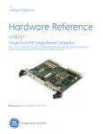
XVME-6300 6U VME Intel i7 Core Processor Board USER’S MANUAL ACROMAG INCORPORATED 30765 South Wixom Road Wixom, MI 48393-7037 U.S.A. Tel: (248) 295-0310 Fax: (248) 624-9234 Email: [email protected] Copyright 2012, Acromag, Inc., Printed in the USA. Data and specifications are subject to change without notice. 8500-981 D Trademark Information Brand or product names are trademarks or registered trademarks of their respective owners. Intel® and Core-i7® are registered trademarks of Intel Corporation. Windows® and Windows 7® are registered trademarks of Microsoft Corporation in the US and in other countries. Copyright Information This document is copyrighted by Xembedded, LLC (Xembedded) and shall not be reproduced or copied without expressed written authorization from Xembedded. The information contained within this document is subject to change without notice. Xembedded does not guarantee the accuracy of the information. WARNING This is a Class A product. In a domestic environment this product may cause radio interference, in which case the user may be required to take adequate measures. Warning for European Users – Electromagnetic Compatibility European Union Directive 89/336/EEC requires that this apparatus comply with relevant ITE EMC standards. EMC compliance demands that this apparatus is installed within a VME enclosure designed to contain electromagnetic radiation and which will provide protection for the apparatus with regard to electromagnetic immunity. This enclosure must be fully shielded. An example of such an enclosure is a Schroff® 7U EMC-RFI VME System chassis, which includes a front cover to complete the enclosure. The connection of non-shielded equipment interface cables to this equipment will invalidate European Free Trade Area (EFTA) EMC compliance and may result in electromagnetic interference and/or susceptibility levels that are in violation of regulations which apply to the legal operation of this device. It is the responsibility of the system integrator and/or user to apply the following directions, as well as those in the user manual, which relate to installation and configuration: All interface cables should be shielded, both inside and outside of the VME enclosure. Braid/foil type shields are recommended for serial, parallel and SCSI interface cables. Where as external mouse cables are not generally shielded, an internal mouse interface cable must either be shielded or looped (1 turn) through a ferrite bead at the enclosure point of exit (bulkhead connector). External cable connectors must be metal with metal back-shells and provide 360-degree protection about the interface wires. The cable shield must be terminated directly to the metal connector shell; shield ground drain wires alone are not adequate. VME panel mount connectors that provide interface to external cables (e.g., RS232, USB, keyboard, mouse, etc.) must have metal housings and provide direct connection to the metal VME chassis. Connector ground drain wires are not adequate. Environmental Protection Statement This product has been manufactured to satisfy environmental protection requirements where possible. Many of the components used (structural parts, printed circuit boards, connectors, batteries, etc.) are capable of being recycled. Final disposition of this product after its service life must be accomplished in accordance with applicable country, state, or local laws or regulations. ii REVISION DESCRIPTION DATE B Initial Release Increased upper limit of temperature specifications for air-cooled assemblies. Added Turbo Mode to programming section. Added XBRD-9050 and XVME-9630 sections. Corrected register addresses on page 2-7. Added testing conditions for temperature specifications. Redefined switch settings for new PCB artwork. 10/11 Added P1 definition table. Added cable drawings. 1/14 B1 C D 2/12 11/12 Technical Support In the unlikely event that you experience problems with your product, contact Technical Support. Please be prepared to provide contact information and details of your problem. You may be asked for further details when calling: TELEPHONE: 248-295-0310 E-mail: [email protected] iii Table of Contents Chapter 1 – Introduction ............................................................................................................................................ 1-1 Module Features ....................................................................................................................................................... 1-1 Architecture ............................................................................................................................................................... 1-1 CPU Chip ............................................................................................................................................................... 1-1 PCI –X Bus Interface ............................................................................................................................................. 1-1 Onboard Memory................................................................................................................................................... 1-2 Ethernet Controller ................................................................................................................................................ 1-2 Storage Devices .................................................................................................................................................... 1-2 VMEbus Interface .................................................................................................................................................. 1-2 Serial Ports ............................................................................................................................................................ 1-2 PMC Expansion ..................................................................................................................................................... 1-3 Software Support ...................................................................................................................................................... 1-3 Operational Block Diagram ....................................................................................................................................... 1-3 Environmental Specifications .................................................................................................................................... 1-4 Hardware Specifications ........................................................................................................................................... 1-4 VMEbus Specification ............................................................................................................................................... 1-5 Ordering Information ................................................................................................................................................. 1-5 Chapter 2 – Installation and Setup ............................................................................................................................ 2-1 Board Layout ............................................................................................................................................................. 2-1 Jumper and Switch Settings ...................................................................................................................................... 2-2 Connectors ................................................................................................................................................................ 2-3 FPANEL ................................................................................................................................................................. 2-4 SERIAL (on optional XBRD-9050 module)............................................................................................................ 2-4 VME P1.................................................................................................................................................................. 2-5 VME P2.................................................................................................................................................................. 2-6 VME P0.................................................................................................................................................................. 2-7 Registers ................................................................................................................................................................... 2-7 Register 0x20A80000h – User LED, Byte Swap, GPIN [3:0] Register ................................................................. 2-8 Register 0x208000h – GPOUT [3:0] Register ....................................................................................................... 2-8 Front Panel Layout .................................................................................................................................................... 2-9 Front Panel LEDs and Reset Switch ..................................................................................................................... 2-9 Installing the XVME-6300 into a Backplane .............................................................................................................. 2-9 Chapter 3 – Programming .......................................................................................................................................... 3-1 CPU Turbo Mode ...................................................................................................................................................... 3-1 VME Interface............................................................................................................................................................ 3-1 System Resources ................................................................................................................................................ 3-1 VMEbus Master Interface ...................................................................................................................................... 3-1 VMEbus Slave Interface ........................................................................................................................................ 3-2 VMEbus Interrupt Handling ................................................................................................................................... 3-3 iv Table of Contents VMEbus Interrupt Generation ................................................................................................................................ 3-3 VMEbus Reset Options ......................................................................................................................................... 3-3 Software-Selectable Byte-Swapping Hardware ........................................................................................................ 3-3 Byte-Ordering Schemes ........................................................................................................................................ 3-3 Numeric Consistency............................................................................................................................................. 3-4 Address Consistency ............................................................................................................................................. 3-5 Chapter 4 – Accessory Modules ............................................................................................................................... 4-1 XBRD-9050 ............................................................................................................................................................... 4-1 Jumpers ................................................................................................................................................................. 4-1 Ordering Information .............................................................................................................................................. 4-1 Jumpers ................................................................................................................................................................. 4-2 Connectors ............................................................................................................................................................ 4-2 Accessory cables ...................................................................................................................................................... 4-4 v Introduction Chapter 1 – Introduction Module Features The XVME-6300 offers the following features: Intel® Core™ i7 Processor. Available models are all dual-core: i7-610E at 2.53GHz, i7-620LE at 2GHz and i7-620UE at 1.06GHz. 4GB or 8GB of DDR3 SDRAM running at 1033MHz (610E, 620LE) or 800MHz (620UE). Two channels of SATA-300 out the P2. Use the XVME-9630 to provide the connectors needed to connect external SATA drives. Quad 10/100/1000 Base T Ethernet controllers with o One port out the front panel RJ-45 connector o Two ports out the P0 to support rear Ethernet (supports Vita 31.1) o One port available on the optional XBRD-9050 module On-Board 1.8” Hard Drive using our XBRD-9050 module. This mounts in the PMC 2 site and does not allow for a PMC module to be used. VME64X VMEbus interface with programmable hardware byte swapping. Support for Vita 31.1 Switch Fabric in compliant back planes. Four serial ports: o Two switchable RS-232/RS-422/RS-485 serial ports (Com 1 & 2) on P2 o One RS-232 serial port (Com3) on optional XBRD-9050 module o One RS-232 serial port on front panel (Com 4) Six Universal Serial Bus (USB 2.0) ports: o Two on front panel connector o Two out P2 o Two on optional XBRD-9050 module PMC (PCI Mezzanine Card) sites with front panel I/O 32/64-bit 33/66/133MHZ PCI-X with full rear I/O using optional P0 connector (PMC 1) and partial I/O using P2 connector (PMC 2). Front panel ABORT/RESET switch with indicating lights. Red for “fail” and green for “pass”. Ejector type handles in IEEE 1101.10 (CompactPCI type) or IEEE 1101.1 (legacy VME type). Conduction cooled models available supporting -40C to 85C operational temperature range. Architecture CPU Chip The Intel® i7 processors have a new micro-architecture, but remain software compatible with previous members of the Intel® microprocessor family. The Intel® Core™ i7-610E, 620LE and 620UE all contain two cores that can run independent processes, potentially doubling performance. With a maximum junction temperature of 105°C, the Intel® Core™ i7 processors are capable of withstanding a great deal of thermal stress. The 18 watt Intel® Core™ i7-620UE 1.06 GHz dual-core processors provide low power options and the 35W Intel® Core™ i7-610E 2.53GHz dual-core processors provide higher performance options. PCI –X Bus Interface The PLX8114 PCI Express x4 to PCI-X bridge provides a PCI-X bus for the TSI-148 and PMC interfaces capable of 32-bit/33MHz up to 64-bit/133MHz bus speeds. PCI-X, or PCI extended, is an enhanced version of PCI (Peripheral Component Interconnect) computer bus. Although PCI-X is backward-compatible with traditional 3.3V PCI 2.0 devices and systems, this specification implements additional features and performance improvements include 3.3V signaling, increased speed grades and adaptation to other form factors. PCI-X effectively doubles the speed and amount of data exchanged between the computer processor and peripherals. PCI-X bus was designed for, and is ideally suited for, server cards such as Fibre Channel, RAID, high-speed networking and other demanding devices. 1-1 Introduction Note that since the PMC connections share the PCI-X bus with the TSI-148 that the VME throughput may suffer when PMC cards are plugged into the XVME-6300, especially if using a slower 33/66MHz PMC card. The PCI-X bus can run up to 133MHz, but will slow down to the speed of the slowest PMC card installed. Onboard Memory SDRAM Memory The XVME-6300 is configured with either 4GB or 8GB of dual channel DDR3 memory, soldered down. Flash BIOS The XVME-6300 system BIOS is contained in an 8MB flash device to facilitate system BIOS updates. Contact Xembedded support for available updates at [email protected] if needed. Be sure to record your current version number and the reason for the request. Ethernet Controller The 82580EB Quad Gigabit Ethernet controller provides up to four 10/100/1000baseT Ethernet interfaces. The 82580EB contains both the MAC and the physical layer. The RJ-45 connectors on the module's front panel provide auto-sensing for 10Base-T, 100Base and 1000Base-TX connections. Each RJ-45 connector has two indicator lights. When mounted vertically, the bottom LED is the link indicator and the top LED is the activity indicator. The optional XBRD-9050 module is needed in order to access the second front panel port. The use of the XVME-9630 is required to connect RJ-45 cables to the rear of the XVME-6300 processor boards. Note that both boards must also have the P0 connector installed. Storage Devices Onboard NANDFlash SSD The XVME-6300 features an onboard 8GB NANDFlash SSD. This SSD is attached via the SATA4 interface and available to operating systems as storage, or can have a bootable operating system installed on it. Serial ATA connection via P2 The XVME-6300 features two SATA-300 drive interfaces out the rear P2 VMEbus connector. The use of the optional rear transition module (XVME-9630) allows for the connection of two drives using standard SATA cables. Serial ATA 1.8” Hard Drive on XBRD-9050 module The XBRD-9050 module can be ordered with an installed 1.8” SATA-300 SSD. This device is connected via the SATA2 interface and can be used for storage or can have a bootable operating system installed on it. VMEbus Interface The XVME-6300 interface to the VMEbus is via a PCI-X to VME bridge device (Tundra TSI-148). The VMEbus interface supports full DMA to and from the VMEbus, integral FIFOs for posted writes, block mode transfers and read-modify-write operations. The interface contains one master and eight slave images that can be programmed in a variety of modes to allow the VMEbus to be mapped into the XVME-6300 local memory. This makes it easy to configure VMEbus resources in protected and real mode programs The XVME-6300 also incorporates onboard hardware byte-swapping. For a complete API, the Xembedded Board Support Packages tailored to your operating system will allow quick programming of your application. Serial Ports XVME-6300 includes four high-speed 16550-compatible serial ports. COM ports 1 and 2, which are available out the P2 connector, are capable of switchable RS-232 and RS-422/485 configurations. There is no onboard termination available for use with RS-422/485 configurations. External cable termination should be applied where necessary. COM port 4 is RS-232 only and available on the front panel connector. COM port 3 is only available with the optional XBRD-9050 module installed. 1-2 Introduction PMC Expansion The XVME-6300 provides two on-board PMC sites for use with standard 32/64-bit, 33/66/133MHz PMC and PMC-X modules. PMC site 1 has full I/O available out the optional rear P0 connector, while PMC 2 has only pins 1-28 available out the rear P2 connector. PCI-X, or PCI extended, is an enhanced version of PCI (Peripheral Component Interconnect) computer bus. Although PCI-X is backward-compatible with traditional PCI devices and systems, this specification implements additional features and performance improvements include 3.3V signaling, increased speed grades and adaptation to other form factors. PCI-X effectively doubles the speed and amount of data exchanged between the computer processor and peripherals. PCI-X bus was designed for, and is ideally suited for, server cards such as FPGA, DSP, Fibre Channel, RAID, high-speed networking and other demanding devices. If a standard PCI PMC card is fitted on the XVME-6300 PMC site, the on-board PCI-X bus reverts to the PCI bus speed, which will also affect the VMEbus interface. Software Support The XVME-6300 is fully PC-compatible and will run "off-the-shelf" PC software, but most packages will not be able to access the features of the VMEbus. To solve this problem, Xembedded has developed extensive Board Support Packages (BSPs) that simplify the integration of VMEbus data into PC software applications. Xembedded’s BSPs provide users with an efficient high-level interface between their applications and the VMEbus-to-PCI bridge device. Board Support Packages are available for Windows 7® and RedHawk Linux. Operational Block Diagram 1-3 Introduction Environmental Specifications ENVIRONMENTAL SPECIFICATION THERMAL Air-cooled 610E 620LE 620UE Extended air-cooled 610E 620LE 620UE Conduction-cooled All HUMIDITY SHOCK VIBRATION 5 - 2000 Hz EMISSIONS IMMUNITY OPERATING NON-OPERATING Air-cooled 0° to 55°C1 w/ 200 lfm airflow 0° to 65°C1 w/ 200 lfm airflow 0° to 70°C1 w/ 200 lfm airflow Extended air-cooled -20° to 60°C2 w/ 200 lfm airflow -20° to 70°C2 w/ 200 lfm airflow -20° to 75°C2 w/ 200 lfm airflow Conduction-cooled -40° to 85°C3 (measured at board/heatsink rail) 20% - 80% RH, non-condensing 30 g peak acceleration, 11msec duration 0.015” (0.38mm) peak-to-peak displacement, 2.5 g maximum acceleration EN 55022 EN 50082-2 Air-cooled -40° to 85°C Extended air-cooled -40° to 85°C Conduction-cooled -55° to 105°C 50 g peak acceleration, 11 msec duration 0.030” (0.76mm) peak-to-peak displacement, 5 g maximum acceleration 1 Designed to meet these temp specifications regardless of system utilization (without PMC/XMC installed). Lesser system utilization and/or higher airflow may allow higher operating temp, although in no case should 85°C be exceeded. CPU temp should be closely monitored for max junction temp of 105°C using a program such as Argus Monitor if exceeding the temps stated here. 2 Every board tested to ensure these temp specifications regardless of system utilization (without PMC/XMC installed). Lesser system utilization and/or higher airflow may allow higher operating temp, although in no case should 85°C be exceeded. CPU temp should be closely monitored for max junction temp of 105°C using a program such as Argus Monitor if exceeding the temps stated here. 3 Every board tested to ensure these temp specifications. Tested under Windows 7 with Passmark BurnInTest version 5.0, running CPU, Memory, and 3D Graphics tests simultaneously. During application testing CPU temp should be closely monitored for max junction temp of 105°C using a program such as Argus Monitor if exceeding measured rail temp of 70°C (thermocouple inside provided heatsink hole). Hardware Specifications CHARACTERISTIC POWER Intel® i7-610E Processor (8GB) Intel® i7-620LE Processor (8GB) Intel® i7-620UE Processor (4GB) VOLTAGE CPU SPEED Intel® i7-610E Processor Intel® i7-620LE Processor Intel® i7-620UE Processor ONBOARD MEMORY Intel® i7-610E Processor Intel® i7-620LE Processor Intel® i7-620UE Processor GRAPHICS CONTROLLER SPECIFICATION +5V: 9.1A (typical); 12.8A (maximum) +5V: 7.5A (typical); 10.8A (maximum) +5V: 6.5A (typical); 9.4A (maximum) +5V, +12V, -12V; all +5%/-2.5% (Only +5VDC required) 2.53 GHz, dual-core 2.0 GHz, dual-core 1.06 GHz, dual-core INTEGRATED SATA-300 CONTROLLER INTEGRATED NAND FLASH SSD 8GB dual channel DDR3 ECC @ 1066 MHz 4GB or 8GB dual channel DDR3 ECC @ 1066 MHz 4GB dual channel DDR3 ECC @ 800 MHz Intel® Integrated HD Graphics 2048 x 1536 max resolution, 32-bit color max (VGA) 1920 x 1200 max resolution, 32-bit color max (DVI-D) Intel® 82580EB Quad Port 10/100/1000Base-TX Gigabit Ethernet SATA0 and SATA1 via P2 8GB on SATA4 ON-BOARD SATA DRIVE One 1.8" SSD drive on SATA2 via optional XBRD-9050 module ETHERNET CONTROLLER 1-4 Introduction PMC SITE STEREO AUDIO USB SERIAL PORTS REGULATORY COMPLIANCE On board 133MHz/64 Bit PMC/PCI-X PMC 1: front I/O and full rear I/O Access via P0. PMC 2: front I/O and limited (Pins 1-28) rear I/O Access via P2 Sites are 3.3V interface level IDT 92HD81Bx HDA CODEC Line Level Stereo Input and Output via P2 Two USB 2.0 via Front panel Two USB 2.0 via P2 Two USB 2.0 via optional XBRD-9050 module 16550 compatible (4) Com 1 and Com2 via P2 (RS-232or RS-422/485 selectable) Com 4 via front panel connector (RS-232 only) Com 3 via optional XBRD-9050 module ( RS-232 only) European Union – CE;3 Electromagnetic Compatibility - 89/336/EEC RoHS Compliant VMEbus Specification VMEbus Compliance Complies with VMEbus Specification ANSI/VITA 1–1994 2eVME and 2eSST protocols to bring support for higher bandwidth A32/A24/A16:D64/D32/D16(EO) DTB Master A32/A24/A16:D64/D32/D16(EO) DTB Slave R(0-3) Bus Requester Interrupter I(1)-I(7) DYN IH(1)-IH(7) Interrupt Handler SYSCLK and SYSRESET Driver PRI, SGL, RRS Arbiter RWD, ROR bus release Ordering Information XVME-6300-ABCD-X A = CPU B = THERMAL, P0 C = MEMORY D = EXTENDED TEMPERATURE X = SOLDER 2 = 1.06 GHz i7-620UE 3 = 2.0 GHz i7-620LE 4 = 2.53 GHz i7-610E 1 = Air Cooled, VME handles, w/ P0 2 = Air Cooled, VME handles, no P0 5 = Conduction, w/ P0 6 = Conduction, no P0 4 = 4Gb memory 8 = 8Gb memory Blank = Standard temperature E = Extended temperature L – Lead solder LF – Lead-free solder 1-5 Installation and Setup Chapter 2 – Installation and Setup Board Layout This chapter provides information on configuring the XVME-6300 modules. It also provides information on installing the XVME-6300 into a backplane. Fig. 2-1 shows the jumper, switch and connector locations on the XVME-6300 2-1 Installation and Setup Jumper and Switch Settings The following section describes the XVME-6300 jumpers and switches, their default positions and their functions. ORBGND 1-2 (default) 2-3 ORB GND TIED TO DIGITAL GND ORB GND ISOLATED CS_PGM 1-2 (default) NORMAL OPERATION 2-3 FACTORY USE ONLY This jumper must be in the 1-2 position for normal operation. The XVME-6300 will not boot with this jumper in 2-3 position. RTCRST 1-2 (default) NORMAL OPERATION 2-3 CLEAR CMOS/RTC To clear CMOS memory, briefly move this jumper to position 2-3. Be sure to move it back to position 1-2 before reapplying power. FPRST 1-2 (default) FRONT PANEL BUTTON RESETS SYSTEM (AND ALSO VME IF SW1-3 IS ON) 2-3 NO PUSHBUTTON RESET In position 1-2, the front panel reset button will reset the XVME-6300 and also reset the VME interface if SW1-3 is ON. In position 2-3, the front panel button will not cause any resets. ME_DIS 1-2 (default) NORMAL OPERATION 2-3 FACTORY USE ONLY This jumper must be in position 1-2 for normal operation. Position 2-3 is used when updating the ME Engine portion of the System Flash. Only use this position if instructed by Xembedded Support. VIDSEL 1-2 (air default) VGA ON FPANEL CONN 2-3 (conduction default) VGA ON P2 CONN In position 1-2, the VGA display is available on the front panel connector. In position 2-3, the VGA display is available on the P2 connector. COM1MD 1-2 (default) COM1 RS-232 2-3 COM1 RS-422/485 In position 1-2, the COM1 serial port uses the RS-232 protocol. In position 2-3, the COM1 serial port uses the RS-422/485 protocols. COM2MD 1-2 (default) COM2 RS-232 2-3 COM2 RS-422/485 In position 1-2, the COM2 serial port uses the RS-232 protocol. In position 2-3, the COM2 serial port uses the RS-422/485 protocols. VCFG1 1-2 (default) SFAILEN bit default = 1 2-3 SFAILEN bit default = 0 The Tsi148 System Failure Enable (SFAILEN) bit controls the assertion of the Tsi148 System Fail Output (SFAILO) signal. The only exception to this is when the Auto Slot ID method of assigning the CR/CSR base address is being implemented. The initial value of the SFAILEN bit can be configured at power-up reset through the VCFG1 jumper. Additionally, a value can be programmed by software in the Control and Status register. VCFG2 1-2 (default) 2-3 VME SYSFAIL AUTO NEGATED VME SYSFAIL NOT AUTO NEGATED 2-2 Installation and Setup The System Failure Auto Slot ID (SFAILAI) bit is used when the Auto Slot ID protocol is enabled in the system to assign the CR/CSR base address. When Auto Slot ID is used to assign the CR/CSR base address, the SFAILAI bit is set by the assertion of the SRSTI_ signal. The SFAILAI bit must be cleared in order for Tsi148’s System Fail Output (SFAILO) signal to be negated. SFAILO is automatically negated if the VCFG2 jumper is in the 1-2 position. Otherwise SFAILO is negated when software clears the SFAILAI bit in the VCTRL register. The initial value of the SFAILAI bit can be configured at power-up reset through the SFAILAI_AC power-up option or a value can be programmed by software in the SFAILAI bit in the VMEbus Control register (VCTRL). VCFG3 1-2 (default) VME AUTO SLOT ID ENABLED 2-3 VME AUTO SLOT ID DISABLED The Auto Slot ID Enable (ASIDEN) feature is controlled through the VCFC3 jumper. The ASIDEN feature allows the CR/CSR base address to be configured using the Auto Slot ID protocol. VCFG4 1-2 (default) VME GEOGRAPHICAL SLOT ID ENABLED 2-3 VME GEOGRAPHICAL SLOT ID DISABLED The Geographic Slot ID Enable function initializes the CR/CSR base address register using the VMEbus GA signals. The Geographic Slot ID Enable feature allows a board to come out of reset with the CR/CSR registers visible from the VMEbus and the base address of the CR/CSR is determined by the VMEbus GA signals. If the VCFG4 jumper is in the 2-3 position the CR/CSR enable bit and CBAR bits are cleared. If the VCFG4 jumper is in the 1-2 position, the CR/CSR enable bit is set and the CBAR bits 7 to 3 are set to the inverted value of the VMEbus geographic address signals. When the SRSTI_ signal is asserted, the CR/CSR EN bit and the CBAR bits are loaded with the power-up option reset values. The initial value of the CR/CSR Enable bit in the CR/CSR Attribute (CRAT) register and CBAR bits in the CR/CSR Base Address (CBAR) register can be configured at power-up reset using the Geographic Slot ID Enable function. SW1 1:2 OFF:OFF SYSCON AUTO-DETECT OFF:ON SYSCON ENABLED ON:OFF SYSCON DISABLED ON:ON SYSCON DISABLED 3 ON LOCAL RESET DRIVES VME SYSRST# OFF LOCAL RESET DOES NOT DRIVE VME SYSRST# 4 ON VME SYSRST# DRIVES LOCAL RESET OFF VME SYSRST# DOES NOT DRIVE LOCAL RESET SW1-1 and SW1-2 control the Auto System Controller (SYSCON) feature. When SW1-1 and SW1-2 are both OFF, The SVME-6300 uses the BG3IN_ signal to enable a board to determine if it is in VMEbus slot 1. If the board is in VMEbus slot 1, the BG3IN_ signal is low and the SCON function is enabled. If the board is not in VMEbus slot 1, the BG3IN_ signal is high and the SCON function is disabled. SW1-3 controls whether a local board reset drives out onto the VMEbus. When SW1-3 is ON the VME SYSRST# line will be driven low to reset the VMEbus whenever the XVME-6300 is reset locally. When SW1-3 is OPEN the VMEbus will not be reset. SW1-4 controls whether the VMEbus can reset the XVME-6300. When SW1-4 is ON the XVME-6300 will be reset when the VME SYSRST# signal is driven low. When SW1-4 is OFF the XVME-6300 will not respond to a VME SYSRST#. Connectors This section provides pin outs for the non-standard connectors on the XVME-6300. Refer to the EMC warning at the beginning of this manual before attaching cables. 2-3 Installation and Setup FPANEL The FPANEL connector ports (USB1, USB2, COM4 and VGA) can be accessed through standard connectors by using the supplied FPANEL dongle cable (P/N 201157). Note that the DB-9 serial connector on this dongle cable is wired as a DTE port. 1 2 3 4 5 6 7 8 9 10 11 12 13 14 15 GND USB Port 0 + USB Port 0 GND +5V USB POWER VGA DDC DATA VGA RED VGA GREEN VGA BLUE GND USB Port 1 + USB Port 1 GND +5V VGA POWER VGA DDC CLK 16 GND RED 17 18 GND GREEN GND BLUE 19 COM4 CTS# 20 COM4 RTS# 21 22 23 24 25 26 COM4 DSR# COM4 DTR# COM4 TXD COM4 RXD VGA VSYNC VGA HSYNC SERIAL (on optional XBRD-9050 module) Note the SERIAL connector on the optional XBRD-9050 module uses a mini USB-B connector. This COM port can be accessed through a standard DB-9 connector by using the supplied adapter cable (P/N 201369). Note that the DB-9 serial connector on this adapter cable is wired as a DCE port. 1 2 3 4 5 N/C COM3 RXD COM3 TXD N/C GND 2-4 Installation and Setup VME P1 PIN 1 Z A B C D MPR BBSY* DO8 +5V 2 GND DO0 DO1 BCLR* D09 GND 3 MCLK DO2 ACFAIL* D10 +V1 4 GND DO3 BG0IN* D11 +V2 5 MSD DO4 BG0OUT* D12 RSVU1 6 GND DO5 BG1IN* D13 -V1 7 MMD DO6 BG1OUT* D14 -V2 8 GND DO7 BG2IN* D15 RSVU2 9 MCTL GND BG2OUT* GND GAP* 10 GND SYCLK BG3IN* SYSFAIL* GA0* 11 RESP* GND BG3OUT* BERR* GA1* 12 GND DS1* BR0* SYSRESET* 13 SDB14* DS0* BR1* LWORD* 14 GND WRITE* BR2* AM5 15 SDB15* GND BR3* A23 16 GND DTACK* AM0 A22 17 SDBP1 GND AM1 A21 GA2* GA3* GA4* 18 GND AS* AM2 A20 19 RSVBUS5 GND AM3 A19 20 GND IACK* GND A18 21 RSVBUS6 IACKIN* NC A17 22 GND IACKOUT* NC A16 23 RSVBUS7 AM4 GND A15 24 GND A07 IRQ7* A14 25 RSVBUS8 A06 IRQ6* A13 26 GND A05 IRQ5* A12 27 RSVBUS9 A04 IRQ4* A11 28 GND A03 IRQ3* A10 29 RSVBUS10 A02 IRQ2* A09 30 GND A01 IRQ1* A08 31 RSVBUS11 -12V NC +12V GND 32 GND +5V +5V +5V +5V RSVBU1 RSVBU2 RSVBU3 RSVBU4 LI/I* LI/O* Some pins in columns Z and D are use internally as test points, these are denoted by italics. These pins are not intended to drive any external devices and MUST not be used for any purpose. 2-5 Installation and Setup VME P2 The following ports are available on the VME P2 connector: SATA0,1; Audio; VGA; DVI; COM1,2; USB3,4; GPI0-3; GPO0-3; PCIE X1; PMC2 I/O pins 1 thru 28. Accessing these ports can be done easily by using the XVME-9630 RTM module, provided the system backplane supports use of RTM modules. PIN Z A B C D PMCB_IO10 SATA_TXP0 +5V AUD_LINEOUT_R DVI_P0_DP 2 GND SATA_TXN0 GND AUD_LINEOUT_L DVI_P0_DN 3 PMCB_IO11 GND RETRY# AGND_AUDIO GND 4 GND SATA_RXP0 A24 AUD_LINEIN_L DVI_P1_DP 5 PMCB_IO12 SATA_RXN0 A25 AUD_LINEIN_R DVI_P1_DN 6 GND GND A26 AUD_SENSE_B GND 7 PMCB_IO13 SATA_TXP1 A27 AGND_AUDIO DVI_P2_DP 8 GND SATA_TXN1 A28 GND DVI_P2_DN 9 PMCB_IO14 GND A29 CRT_REAR_RED GND 10 GND SATA_RXP1 A30 CRT_REAR_GREEN CLK_DVI_DP 11 PMCB_IO15 SATA_RXN1 A31 CRT_REAR_BLUE CLK_DVI_DN 1 12 GND GND GND CRT_REAR_VSYNC GND 13 PMCB_IO16 USB_P2_DP +5V CRT_REAR_HSYNC DVI_HPD 14 GND USB_P2_DN VD16 GND DVI_SDA 15 PMCB_IO17 GND VD17 REAR_DDC_DATA DVI_SCL 16 GND USB_P3_DP VD18 REAR_DDC_CLK GND 17 PMCB_IO18 USB_P3_DN VD19 GND PCIE_PCH_RTM_DP PCIE_PCH_RTM_DN 18 GND GND VD20 COM2_TX 19 PMCB_IO19 V_5V_USB_P2 VD21 COM2_422_485_TX- PCIE_RTM_PCH_DP 20 GND V_5V_USB_P2 VD22 GND PCIE_RTM_PCH_DN 21 PMCB_IO20 GND VD23 COM2_RX GND 22 GND COM_1_TX GND COM2_422_485_RX- PMCB_IO1 23 PMCB_IO21 COM1_RTS#_422_485_TX VD24 GND PMCB_IO2 24 GND GND VD25 VME_GPIN0 PMCB_IO3 25 PMCB_IO22 COM_1_RX VD26 VME_GPIN1 PMCB_IO4 26 GND COM1_DSR#_422_485_RX- VD27 VME_GPIN2 PMCB_IO5 27 PMCB_IO23 GND VD28 VME_GPIN3 PMCB_IO6 28 GND COM1_CTS# VD29 VME_GPOUT0 PMCB_IO7 29 PMCB_IO24 COM1_DTR# VD30 VME_GPOUT1 PMCB_IO8 30 GND PMCB_IO26 VD31 VME_GPOUT2 PMCB_IO9 31 PMCB_IO25 PMCB_IO27 GND VME_GPOUT3 GND 32 GND PMCB_IO28 +5V PCIE_RST# +5V P2 I/O Signal Requirements This section provides the information necessary to interface with the P2 I/O signals, without using a XVME-9630 RTM module. VGA: For proper operation of the VGA display, 150ohm termination to GND is required on the CRT_REAR_RED, CRT_REAR_GREEN and CRT_REAR_BLUE signals. Failure to apply this termination may result in poor display quality and improper operation of Intel® HD Graphics control panel in Windows®. Also for proper monitor detection, the REAR_DDC_CLK and REAR_DDC_DATA lines should be level shifted to +5V. See the following for suggested interface schematic: 2-6 Installation and Setup It is strongly suggested that ESD protection be included in interface circuitry on the VGA and USB ports. Failure to do so may cause damage the XVME-6300 in the event of an ESD discharge into the I/O pins. VME P0 The following ports are available on the VME P0 connector: Ethernet 0, Ethernet 1 and PMC1 I/O. Accessing these ports can be done easily by using the XVME-9630 RTM module with 2 port Ethernet PIM installed, provided the system backplane supports use of RTM modules. Ethernet 0 and Ethernet 1 also support Vita 31.1 Switch Fabric in compliant back planes. PIN F E D C B A 1 GND GND GND GND GND GND 2 GND ENET0_P2_DN ENET0_P2_DP GND ENET0_P0_DN ENET0_P0_DP 3 GND ENET0_P3_DN ENET0_P3_DP GND ENET0_P1_DN ENET0_P1_DP 4 GND ENET1_P2_DN ENET1_P2_DP GND ENET1_P0_DN ENET1_P0_DP 5 GND ENET1_P3_DN ENET1_P3_DP GND ENET1_P1_DN ENET1_P1_DP 6 GND ENET0_ACT# ENET1_ACT# +3.3V to RTM ENET0_LINK# ENET1_LINK# 7 GND PMCA_IO1 PMCA_IO2 PMCA_IO3 PMCA_IO4 PMCA_IO5 8 GND PMCA_IO6 PMCA_IO7 PMCA_IO8 PMCA_IO9 PMCA_IO10 9 GND PMCA_IO11 PMCA_IO12 PMCA_IO13 PMCA_IO14 PMCA_IO15 10 GND PMCA_IO16 PMCA_IO17 PMCA_IO18 PMCA_IO19 PMCA_IO20 11 GND PMCA_IO21 PMCA_IO22 PMCA_IO23 PMCA_IO24 PMCA_IO25 12 GND PMCA_IO26 PMCA_IO27 PMCA_IO28 PMCA_IO29 PMCA_IO30 13 GND PMCA_IO31 PMCA_IO32 PMCA_IO33 PMCA_IO34 PMCA_IO35 14 GND PMCA_IO36 PMCA_IO37 PMCA_IO38 PMCA_IO39 PMCA_IO40 15 GND PMCA_IO41 PMCA_IO42 PMCA_IO43 PMCA_IO44 PMCA_IO45 16 GND PMCA_IO46 PMCA_IO47 PMCA_IO48 PMCA_IO49 PMCA_IO50 17 GND PMCA_IO51 PMCA_IO52 PMCA_IO53 PMCA_IO54 PMCA_IO55 18 GND PMCA_IO56 PMCA_IO57 PMCA_IO58 PMCA_IO59 PMCA_IO60 19 GND PMCA_IO61 PMCA_IO62 PMCA_IO63 PMCA_IO64 NC Registers The XVME-6300 modules contain the following Xembedded-defined I/O registers: 2-7 Installation and Setup Register 0x20A80000h – User LED, Byte Swap, GPIN [3:0] Register This register contains User LEDs, Byte Swap address location and GPIN [3:0] BIT SIGNAL 0:3 4 5 6 7 8:15 16 Reserved GPIN0 GPIN1 GPIN2 GPIN3 Reserved USER LED 0 17 18:20 21 22 23 24 25 26:31 RESULT Reserved Reads value of GPIN0 signal Reads value of GPIN1 signal Reads value of GPIN2 signal Reads value of GPIN3 signal Reserved 0 = LED OFF 1 = LED ON USER LED 1 0 = LED OFF 1 = LED ON Reserved Reserved SWAPM 1 = No swapping (data invariant) occurs during master cycles Reserved Reserved SWAPS 1 = No swapping (data invariant) occurs during slave cycles Reserved Reserved USER LED 2 0 = LED OFF 1 = LED ON Reserved Reserved Table 2-2 User LED, Byte Swap, GPIN [3:0] Register Settings Register 0x208000h – GPOUT [3:0] Register This register contains GPOUT [3:0] BIT SIGNAL RESULT 0:9 Reserved Reserved 10 GPO0 Controls signal level of GPO0 signal 0 = GPO is low 1 = GPO is high 11 GPO1 Controls signal level of GPO1 signal 0 = GPO is low 1 = GPO is high 12:15 Reserved Reserved 16 GPO2 Controls signal level of GPO2 signal 0 = GPO is low 1 = GPO is high 17 GPO3 Controls signal level of GPO3 signal 0 = GPO is low 1 = GPO is high 18:31 Reserved Reserved Table 2-3 GPOUT [3:0] Register Settings Note Changing the value of ‘Reserved’ register bits may result in system instability. 2-8 Installation and Setup Front Panel Layout Fig. 2-4 shows the front panel connector locations and indicator LEDs Front Panel LEDs and Reset Switch The reset switch can be configured to either reset the XVME-6300, or to reset both the VMEbus and the XVME-6300. The green pass and red fail LEDs are used as an indication of board health during the BIOS boot up. As the BIOS starts the POST, the red fail LED will be turned off. When the BIOS completes POST, the green PASS LED is turned on. Installing the XVME-6300 into a Backplane This section provides the information necessary to install the XVME-6300 into the VMEbus backplane. The XVME6300 is a double-high, single-slot VMEbus module. Note Xembedded modules are designed to comply with all physical and electrical VMEbus backplane specifications of VME64x. Note The XVME-6300 is available from the factory in two basic configurations, with P0 and without P0. Without P0 would normally be used in a legacy system, because most of these racks are equipped with a stiffener bar in the P0 location. Also note that to use the extended features of the XVME-6300, the backplane must use 160-pin P1 and P2. Caution Do not install the XVME-6300 on a VMEbus system without a P2 backplane. 2-9 Installation and Setup Warning Never install or remove any boards before turning off the power to the bus and all related external power supplies. 1. Disconnect all power supplies to the backplane and the card cage. Disconnect the power cable. 2. Make sure backplane connectors P1 and P2 are available. 3. Verify that all jumper settings are correct. 4. Verify that the card cage slot is clear and accessible. 5. Install the XVME-6300 in the card cage by centering the unit on the plastic guides in the slots (P1 connector facing up). Push the board slowly toward the rear of the chassis until the P1 and P2 connectors engage. The board should slide freely in the plastic guides. Caution Do not use excessive force or pressure to engage the connectors. If the boards do not properly connect with the backplane, remove the module and inspect all connectors and guide slots for damage or obstructions. 6. Secure the module to the chassis by tightening the machine screws at the top and bottom of the board. 7. Connect all remaining peripherals by attaching each interface cable into the appropriate connector on the front or rear of the XVME-6300 board. 2-10 Programming Chapter 3 – Programming CPU Turbo Mode The Intel i7 processors have a Turbo Mode feature that is essentially an ‘on-demand’ overclocking mechanism that can run the CPU temporarily faster than the maximum rated CPU frequency when both cores of the CPU are not 100% utilized. This mode of operation results in large instantaneous dynamic swings in power supply current. As a result, spurious resets of the board may be experienced with Turbo Mode enabled if the power supply and/or backplane combination are insufficient. Turbo Mode can be enabled/disabled in the BIOS setup. It can be found in the Advanced > Thermal Configuration screen. Note With Turbo Mode enabled a power supply and/or backplane combination incapable of supplying large instantaneous current surges may result in spurious resets of the board. VME Interface The VME interface is the Tundra TSI-148 chip, which is a PCIbus-to-VMEbus bridge device. The XVME-6300 implements a 64-bit PCI-X bus and a 32/64-bit VMEbus interface. The TSI-148 chip configuration registers are located in a 4 KB block of PCI memory space. This memory location is programmable and defined by PCI configuration cycles. The VMEbus controller has four main functions; system resources or the “traffic cop of the bus”, master interface which “starts conversation on the bus”, slave interface which responds to a bus master’s question and the interrupt functions which uses seven levels of interrupt control. Note For your frame of reference, the left side below is the XVME-6300 board and the right side below is the VMEbus. PCI memory slave access = VMEbus master access PCI memory master access = VMEbus slave access System Resources The XVME-6300 automatically provides slot 1 system resource functions (also referenced as SysCon) if the Bus Grant 3 jumpers are set correctly on the VMEbus backplane. The system resource functions are explained in the TSI-148 manual. (Contact Tundra at www.tundra.com for a PDF version of the TSI-148 manual.) This function can be disabled using the XVME-6300’s SW1 switch. See Switch Settings in Chapter 2 (p.2-2). VMEbus Master Interface The XVME-6300 can be either a VMEbus master by accessing a PCI slave channel or the DMA channel initiates a transaction. There are 8 PCI slave images. The first PCI slave image has a 4K resolution the other have 64K resolution. The master can generate A16, A24 and A32 VMEbus cycles for each PCI slave image. The address mode and type are also programmed on a PCI slave image basis. The PCI memory address location for the VMEbus master cycle is specified by the Base and Bound address. The VME address is calculated by adding the Base address to the Translation offset address. All PCI slave images are located in the PCI bus Memory Space. The master cycles are all byte swapped maintaining address coherency. 3-1 Programming Caution: PCI slave images mapped to a system DRAM area will access the system DRAM not the PCI slave image. Also the TSI-148 configuration register has a higher priority than the PCI slave images. This means if the PCI slave image and the TSI-148 configuration registers are mapped in to the same memory area the configuration registers will take precedence. VMEbus Slave Interface The XVME-6300 can be either a VMEbus slave by being accessing a VMEbus slave image or the DMA channel initiates a transaction. There are eight PCI slave images. The first slave image has a 4K resolution the others (2-4, 6-8) have 64K resolution. Slave images 1-8 have been implemented on the XVME-6300. The slave can respond to A16, A24 and A32 VMEbus cycles for each VMEbus slave image. The address mode and type are also programmed on a VMEbus slave image basis. The VMEbus memory address location for the VMEbus slave cycle is specified by the Base and Bound address. The PCI address is calculated by adding the Base address to the Translation offset address. The XVME-6300 DRAM memory is based on the PC/AT architecture and is not contiguous. The VMEbus Slave Images may be setup to allow this DRAM to appear as one Contiguous block. The first VMEbus slave Image must have Base and Bound register set to 640K. (Example: VMEbus Slave Image 0 BS= 0000000h BD= A0000h TO = 0000000h) The second VMEbus Slave Image must have the Base register set to be contiguous with the Bound register from the first VMEbus Slave Image. The Bound register is limited by the Total XVME-6300 DRAM. The Translation Offset register is offset by 384K which is equivalent to the A0000h-FFFFFh range on the XVME-6300 board. (Example: VMEbus Slave Image 1 BS=A0000h BD= 400000h TO = 060000h) This rather awkward mapping defined by the PC/AT architecture can also be over come if the VMEbus Slave Image window is always configured with a 1Mbyte Translation Offset. From a user and software standpoint this is always more desirable because the interrupt vector table, system parameters and communication buffers (keyboard) are placed in low DRAM. This provides for more system protection. Caution: When setting up slave images the address and other parameters should be set first. Then only after the VMEbus slave image is set up correctly should the VMEbus slave image be enabled. If a slave image is going to be remapped disable the slave image first then reset the address. After the image is configured correctly enable the image again. The VMEbus slave cycle becomes a master cycle on the PCI bus. The PCI bus arbiter is the PEX8114. It arbitrates between the various PMC masters, the TSI-148, and the i7. Because the VMEbus cannot be retried, all VMEbus slave cycles must be allowed to be processed. This becomes a problem when an i7® cycle to the PCI slave image is in progress while a VMEbus slave cycle to the onboard DRAM is in progress. The i7® cycle will not give up the PCI bus and the VMEbus slave cycle will not give up the VMEbus thus the XVME-6300 becomes deadlocked. If the XVME-6300 is to be used as a master and a slave at the same time, the VMEbus master cycles must obtain the VMEbus prior to initiating VMEbus cycles. All Slave interface cycles are byte swapped to maintain address coherency. 3-2 Programming VMEbus Interrupt Handling The XVME-6300 can service IRQ [7:1]. A register in the TSI-148 enables which interrupt levels will be serviced by the XVME-6300. When a VMEbus IRQ is asserted the TSI-148 requests the VMEbus and generates an IACK cycle. Once the IACK cycle is complete a PCI bus interrupt is generated to allow the proper ISR (Interrupt service routine) to be executed. The TSI-148 connects to all four PCI bus interrupts. These interrupts may be shared by other PCI bus devices. The BIOS maps the PCI bus interrupts to the ATbus Interrupt controllers. The AT-bus interrupts must be uniquely mapped to each device. Because the PCI devices share interrupt lines, all ISR routines must be prepared to chain the interrupt vector to allow the other devices to be serviced. VMEbus Interrupt Generation The XVME-6300 can generate VMEbus interrupts on all seven levels. There is a unique STATUS/ID associated with each level. The upper bits are programmed in the STATUS/ID register. The lowest bit is cleared if the source of the interrupt is a software interrupt and set for all other interrupt sources. Consult the TSI-148 Users Manual for a more in depth explanation. VMEbus Reset Options When the front panel Reset switch is toggled, the XVME-6300 can perform the following reset options: 1. Reset the XVME-6300 CPU only. 2. Reset the XVME-6300 CPU and VME backplane. 3. Reset neither. See Switch Settings in Chapter 2 (p.2-2) for information on how to configure SW1 for the Reset options. Software-Selectable Byte-Swapping Hardware The VMEbus can be used to communicate to either Intel® based modules or a Motorola based modules. These two companies have created data transaction that use different byte ordering in their data storage. A hardware approach to swapping these byte orders is a faster solution when compared to a software only byte-swapping method. Software selectable byte-swapping hardware is integrated into the XVME-6300 to allow for the difference between the Intel® and Motorola byte-ordering schemes, allowing easy communication over the VMEbus. The byte-swapping package incorporates several buffers either to pass data straight through or to swap the data bytes as they are passed through. Note The configurable byte-swapping hardware is only supported for D16 and D32 cycles. If byte swapping is required with other types of data access, implementation through software will be necessary. Byte-Ordering Schemes The Motorola family of processors stores data with the least significant byte located at the highest address and the most significant byte at the lowest address. This is referred to as a big-endian bus and is the VMEbus standard. The Intel® family of processors stores data in the opposite way, with the least significant byte located at the lowest address and the most significant byte located at the highest address. This is referred to as a little-endian (or PCI) bus. This fundamental difference is illustrated in Figure 3-1, which shows a 32-bit quantity stored by both architectures, starting at address M. 3-3 Programming Address INTEL MOTOROLA Low Byte M High Byte M+1 M+2 High Byte M+3 Low Byte Fig. 3-1 shows byte ordering schemes Note The two architectures differ only in the way in which they store data into memory, not in the way in which they place data on the shared data bus. The XVME-6300 contains a TSI-148 chip that performs address-invariant translation between the PCIbus (Intel® architecture) and the VMEbus (Motorola architecture) and byte-swapping hardware to reverse the TSI148 chip byte-lane swapping. (Contact Tundra at www.tundra.com for a PDF version of the TSI-148 manual.) Figure 4-2 shows address-invariant translation between a PCI bus and a VMEbus. Fig. 3-2 shows address-invariant translation Notice that the internal data storage scheme for the PCI (Intel®) bus is different from that of the VME (Motorola) bus. For example, the byte 78 (the least significant byte) is stored at location M on the PCI machine while the byte 78 is stored at the location M+3 on the VMEbus machine. Therefore, the data bus connections between the architectures must be mapped correctly. Numeric Consistency Numeric consistency, or data consistency, refers to communications between the XVME-6300 and the VMEbus in which the byte-ordering scheme described above is maintained during the transfer of a 16-bit or 32-bit quantity. Numeric consistency is achieved by setting the XVME-6300 buffers to pass data straight through, which allows the TSI-148 chip to perform address-invariant byte-lane swapping. Numeric 3-4 Programming consistency is desirable for transferring integer data, floating-point data, pointers, etc. Consider the long word value 12345678h stored at address M by both the XVME-6300 and the VMEbus, as shown in Figure 3-2. Fig. 3-2 shows maintaining numeric consistency Due to the TSI-148, the data must be passed straight through the byte-swapping hardware. To do this, maintaining numeric consistency, enable the straight-through buffers by setting bits 21 and 23 of register 0x20A80000h to 1 (see p. 2-8). Note With the straight-through buffers enabled, the XVME-6300 does not support unaligned transfers. 16-bit or 32-bit transfers must have an even address. Address Consistency Address consistency, or address coherency, refers to communications between the XVME-6300 and the VMEbus in which both architectures' addresses are the same for each byte. In other words, the XVME-6300 and the VMEbus memory images appear the same. Address consistency is desirable for byte-oriented data such as strings or video image data. Consider the example of transferring the string Text to the VMEbus memory using a 32-bit transfer in Figure 3-3. 3-5 Programming Fig. 3-3 shows maintaining address consistency Notice that the data byte at each address is identical. To achieve this, the data bytes need to be swapped as they are passed from the PCI bus to the VMEbus. To maintain address consistency, enable the byte-swapping buffers by setting bits 21 and 23 of register 0x20A80000h to 0 (see p. 2-8). 3-6 Accessory Modules Chapter 4 – Accessory Modules XBRD-9050 The optional XBRD-9050 expansion module is installed in PMC site 2 and adds the following connectors to the front panel: Fig. 4-1 shows the XBRD-9050-000 The module can also hold a 1.8” rotating or SSD SATA drive. Note that drives should not be used outside their rated operational temperature range (usually 0° to 60°C for rotating drives). Jumpers There is one jumper on the XBRD-9050 module. It either connects or isolates the front panel ORB GND to digital GND as follows: ORBGND 1-2 (default) 2-3 ORB GND TIED TO DIGITAL GND ORB GND ISOLATED Ordering Information XBRD-9050-000 expansion module with no drive included. 4-1 Accessory Modules XVME-9630 The base board contains a standard 15-pin VGA, 2 standard USB ‘A’, 2 standard 7-pin SATA, 2 10-pin COM headers, 5-pin audio. PIM modules are used to add additional connectors. Custom PIMs are available, including PIMs to interface PMC I/O. Fig. 4-2 shows the XVME-9630-102 The following configurations are available: XVME-9630-100 Rear Transition Module with P0, VGA, (2)USB, (2)SATA, audio, (2)Serial, (4)GPI, and (4)GPO XVME-9630-102 Same as XVME-9630-100 plus Dual Ethernet XVME-9630-103 Same as XVME-9630-100 plus DVI XVME-9630-200 Rear Transition Module without P0- includes VGA, (2)USB, (2)SATA, audio, (2)Serial, (4)GPI, and (4)GPO XVME-9630-203 Same as XVME-9630-200 plus DVI The I/O from PMC Site 1 on the XVME-6300 is available via a standard VITA 36 I/O PIM module connected to the PMCA_PIM connectors. The limited I/O from PMC Site 2 on the XMVE-6300 is available via a custom PIM module connected to the PMCB_PIM connector. Jumpers There are two jumpers on the XVME-9630 module, as follows: ORBGND 1-2 (default) ORB GND TIED TO DIGITAL GND 2-3 ORB GND ISOLATED COM1MD 1-2 (default) 2-3 Connects DTR# to COM1 connector pin 7. Connects TX- to COM1 connector pin7. Connectors This section provides pin outs for some of the XVME-9630 connectors. Refer to the EMC warning at the beginning of this manual before attaching cables. 4-2 Accessory Modules COM1 The COM1 port can be accessed through a standard DB-9 connector by using a DB9M TO IDC10 SERIAL (DTK) cable. Here is the pinout of the 10-pin COM1 connector: 1 6 NO CONNECT DSR# (RS-232) RX- (RS-422/485) RXD (RS-232) RX+ (RS-422/485) RTS# (RS-232) TX- (RS-422/485) TXD (RS-232) TX+ (RS-422/485) CTS# (RS-232) 7 SEE COM1MD JUMPER TABLE ABOVE 8 NO CONNECT 9 GROUND 10 GROUND 2 3 4 5 COM2 The COM2 port can be accessed through a standard DB-9 connector by using a DB9M TO IDC10 SERIAL (DTK) cable. Here is the pinout of the 10-pin COM2 connector: 1 NO CONNECT 2 6 RX- (RS-422/485) RXD (RS-232) RX+ (RS-422/485) NO CONNECT TXD (RS-232) TX+ (RS-422/485) NO CONNECT 7 TX- (RS-422/485) 8 NO CONNECT 9 GROUND 10 GROUND 3 4 5 AUDIO 1 LINE OUT LEFT 2 LINE OUT RIGHT 3 GROUND 4 LINE IN LEFT 5 LINE IN RIGHT GPIO The 14-pin 2mm pitch GPIO header can be used to access the VME GPINs and GPOUTs from the XVME-6300. 1 GPOUT0 2 GPIN0 3 GPOUT1 4 GPIN1 5 GPOUT2 6 GPIN2 7 GPOUT3 8 GPIN3 4-3 Accessory Modules 9 NO CONNECT 10 NO CONNECT 11 NO CONNECT 12 NO CONNECT 13 NO CONNECT 14 NO CONNECT Accessory cables The serial cable for the XBRD-9050, that is included with this board, is P/N 4001129. In case this does not suit the customer needs, the customer can build their own. The following drawing is here for reference. Note: Acromag cannot be responsible for a customer built cable. 4-4 Accessory Modules The I/O cable for the XVME-6300, that is included with this board, is P/N 4001128 In case this does not suit the customer needs, the customer can build their own. The following drawing is here for reference. Note: Acromag cannot be responsible for a customer built cable. 4-5