1
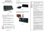
Wired / Wireless / POE IP Camera
ICA-107 / ICA-107W / ICA-107P
ICA-M220 / ICA-M220W
Quick Installation Guide
Table of Contents
Chapter 1. Introduction.................................................................... 3
1.1 Before Installation................................................................ 3
Chapter 2. ICA-107 Series–CMOS IP Camera..................................... 4
2.1 Package Content.................................................................. 4
2.2 Outlook............................................................................... 4
2.2.1 Front View.................................................................. 4
2.2.2 Button View................................................................ 6
2.3 Physical Installation ............................................................. 7
2.4 IP Camera Admin Software................................................... 7
Chapter 3. Mega-Pixel CMOS PT IP Camera......................................13
3.1 ICA-M220 Mega-Pixel CMOS PT IP Camera............................13
3.1.1 Package Content........................................................13
3.2. ICA-M220W 11n Mega-Pixel CMOS PT IP Camera..................13
3.2.1 Package Content........................................................13
3.3 Front Panel.........................................................................14
3.4 Rear Panel..........................................................................15
3.6 Physical Installation.............................................................16
3.7 Initial Utility Installation.......................................................18
3.8 Camera Admin locate PT Internet Camera.............................22
Chapter 4. Cam Viewer Plus Installation...........................................24
Appendix A: Feature Listing for Cam Viewer Plus...............................29
Appendix B: Suggest Hardware / System Requirement......................30
Ordering Information for Cam Viewer Plus Pro.............................31
Further Configuration.................................................................31
Chapter 1. Introduction
Thank you for purchasing the IP surveillance product. It is versatile
and high image solution of the perfect surveillance application. The IP
surveillance state-of-art design is considerable to fit in various network
environments.
1.1 Before Installation
Before installation, please be sure to read this quick installation guide
and user’s manual (CD) carefully to complete machine installation.
This QIG includes the following chapter:
• Chapter 2. ICA-107 Series – CMOS IP Camera
• Chapter 3. ICA-M220/M220W – Mega-Pixel CMOS PT IP Camera
• Chaoter 4. Cam Viewer Plus Installation
• Appendix A: Feature Listing for Cam Viewer Plus
• Appendix B: Suggest Hardware / System Requirement
Chapter 2. ICA-107 Series –CMOS IP Camera
2.1 Package Content
CMOS IP Camera x 1
Power Adapter x 1
Camera Stand x 1
Network Cable x 1
Antenna x 1 (ICA-107W only)
CD Disk x 1
Quick Installation Guide x 1
Note
1. If any of the above items are missing, please contact
your dealer immediately.
2. Using a power supply with a different voltage that the
one included with the package will cause damage and
void the warranty.
2.2 Outlook
2.2.1 Front View
ICA-107 & ICA-107P
LAN LED
Power LED
ICA-107W
Antenna Connector
LAN LED
Wireless LED
Power LED
LED
Description
LAN LED
When the Internet Camera is linking to wired
network, the LED is lighting. The LED is flashing
when video is transmitted or received through
wired network.
Power LED
When the camera is power on, the LED will
light.
Wireless LED
(ICA-107W only)
When the Internet Camera is linking to wireless
network, the LED is lighting. The LED is flashing
when video is transmitted or received through
wireless network.
2.2.2 Button View
ICA-107 & ICA-107W
Ethernet Jack (RJ45)
Reset Button
Power Input
ICA-107P
Ethernet Jack
(RJ45, 802.3af)
Reset Button
Power Input
PORT
Description
12V DC
Connect to the supplied power adapter.
If ICA-107P is obtained power from PoE, you
don’t have to attach the power adapter.
LAN
Connect your camera to a 10/100Base-TX hub
or switch.
Connect your camera to a 10/100Base-TX hub
or switch.
LAN (PoE)
This port compliant with IEEE 802.3af PoE PD
(Model: ICA-107P)
(powered device). Either mid-span PSE or endspan PSE supported.
RESET
Reset to manufacturer default valued.
When pressed and held over 5 seconds, the
settings will be set to the default values.
2.3 Physical Installation
1.Connect an Ethernet cable
Connect one end of an Ethernet cable to the LAN port located on the IP
Camera bottom panel and attach the other end to the network device
(hub or switch).
2.Attach the external power supply
Connect the provided power adapter to the IP Camera’s connector
labeled “12V DC” on the bottom panel.
Note
1. Please use the power adapter that is bundled in
the package. Using a power supply with a different
voltage rating will damage and void the warranty for
this product.
2. For ICA-107P, either powered from AC adapter, or
from PoE is allowed.
3.Check the LEDs
The power LED should be on.
2.4 IP Camera Admin Software
Follow the steps below to install the initial utility. The following
installation is implemented in Windows XP and the installation
procedure is similar to Windows 2000.
1.Insert the bundle CD disk into your CD-ROM drive. A welcome web
page should open with your default browser. If not, please double
click on the “default.htm” in the CD.
2.Please click the IP Camera model name.
3.Click on the hyperlink “IP Camera initial utility”.
4.After clicking on the “Install IP Camera Configure Utility” hyperlink,
you may see a dialog box to prompt you to download the installation
program. Click on the “Run” button, the installation program should
be started.
5.Click “Next” to start the installation.
6.Click on the “Change” button to choose the destination you wished to
install the utility. If no specific requirement, leave the default setting
and click “Next”.
7.Click “Install” to start installing the utility.
8.The system will install the program automatically.
9.Click “Finish” to complete the software installation.
10
10.After the installation, IP Camera Admin will launch automatically.
It will start to search the IP Cameras in your intranet and it will
list all the available ICA-107 series on the camera list. Choose the
one that you would like to configure and click “Setting Wizard” to
processed.
Camera list
11.Please enter the default password “Admin” and click “OK” to login
to the IP Camera’s setup page.
11
12.For IP Camera work, you may assign a new IP address to your
IP Camera. The utility will try to find an available IP address and
recommend you using that address. You could use the recommend
IP address or input the IP address manually. Please be aware that
the IP address of the IP Camera and your PC should be in the
same subnet. Click “Finish” to apply the configuration.
13.After modifications, you may now connect the IP Camera via web
browser.
12
Chapter 3. Mega-Pixel CMOS PT IP Camera
3.1 ICA-M220 Mega-Pixel CMOS PT IP Camera
3.1.1 Package Content
IP Camera x 1
Power Adapter x 1
Quick Installation Guide x 1
User’s Manual CD x 1
RJ-45 Cable x 1
Mounting Kit x 1
Note
1. if any of the above items are missing, please contact
your dealer immediately.
2. Using a power supply with a different voltage that the
one included with the package will cause damage and
void the warranty.
3.2. ICA-M220W 11n Mega-Pixel CMOS PT IP Camera
3.2.1 Package Content
ICA-M220W x 1
Power Adapter x 1
Quick Installation Guide x 1
User’s Manual CD x 1
RJ-45 Cable x 1
Mounting Kit x 1
Antenna x 2
Note
1. if any of the above items are missing, please contact
your dealer immediately.
2. Using a power supply with a different voltage that the
one included with the package will cause damage and
void the warranty.
13
3.3 Front Panel
Focus Ring
Microphone
Audio LED
LAN LED
Power LED
WLAN LED
Indicators
Description
Focus Ring
User could use this ring to adjust focus
manually.
LAN LED
The LED indicates LAN activity.
It be flashing while network accessing via
Ethernet.
The LED indicates the wireless accessing of the
PT Internet Camera.
WLAN LED
Light be flashing while transferring via wireless
(ICA-M220W only) LAN. If be flashing at low speed once a second
indicated that waiting for WPS connection form
AP.
Microphone
The Camera has built-in an internal
microphone. This microphone is hidden in the
pinhole located on the front panel.
Audio LED
The LED indicates the audio activity, when it is
flashing while speak function enable, if volume
adjust to 0 the function will be disable.
Power LED
The LED is used to indicate DC power status.
14
3.4 Rear Panel
SD Card Slot
Audio Connector
LAN
WPS Button
Antenna Base
Power Connector
Connectors
Reset Button
Description
Audio Connector
Audio-Out allows device to output audio or
alerting sound.
LAN
This is a RJ-45 connector for connections
to 10/100 Base-TX Ethernet cabling and
built N-Way protocol can detect or negotiate
the transmission speed of the network
automatically.
Reset Button
Press the button with pen nib and hold for 5
seconds to reset the camera settings to factory
default value.
SD Card Slot
Accepts SD / SD-HC memory card for image /
video storage
Antenna Base
Allows device connects to the supplied
(ICA-M220W only) antenna.
WPS Button
Press the button on IP Cam and press it on
(ICA-M220W only) the AP you want to connect for wireless.
Power Connector
The input power is 12VDC, 1A.
Only use the power adapter supplied
with PT Internet Camera, otherwise the
product may be damaged.
15
3.6 Physical Installation
Please follow the following instructions to set your IP camera up.
1.Unpack the product package and check if anything’s missing.
2.Connect the Ethernet cable to your local area network, and connect
the other end to the LAN jack of this IP camera.
Note
User can skip this step if you plan to use wireless LAN
only
Plug the power adapter to wall socket, and connect the power
connector to the power jack located at the bottom of the IP camera,
16
3.(ICA-M220W only) Connect two antennas to the antenna bases,
which is located at the back of the PT Internet Camera.
4.Place the camera at a secure place, and point the camera to the
place you wish to monitor. If you wish to hang the camera on the
ceiling or wall, please use the tripod connector (located at the bottom
of the camera) to secure the camera.
Lock
Launch Internet Explorer on your computer, and following
instructions given in next section to set the PT Internet Camera.
the
17
3.7 Initial Utility Installation
This section shows how to quick set up your PT Internet Camera. The
Camera is with the default settings. However to help you find the
networked camera quickly the admin software can search the cameras
in the network that shall help you to configure some basic setting
before you started advanced management and monitoring.
Initial setup should be performed by using the supplied Windows-based
Setup Tool as follows:
Then follow the following instructions to install and use camera admin
software:
1.Insert the bundled product CD into CD-ROM drive to launch the
autorun program.
2.Please click the IP camera model name.
3.When the web page displayed, select and click the “Initial Utility”
hyperlink on the menu to start the installation process.
Note
If the CD’s menu does not appear, click “Start” on the
task bar and select “Run” to type “X:\Utility\InitialUtility\
Setup_ICA-M220_x.x.x.EXE”, assume X is your CDROM drive.
4.Click Next to start install camera admin software:
18
5.You can change the installation folder of camera setup software here,
click Browse to select an existing folder, or you can just click Next
to use default installation folder:
6.If you wish to create desktop icon and / or quick launch icon for
camera admin software, please check corresponding box, and click
Next to continue.
19
7.You’ll see a brief of all options you selected, click Install to install
camera admin software now, or click back to back to previous steps
to change settings.
8.When you see this message, the installation of camera admin software is complete. If you wish to launch camera admin software now,
keep Launch IP Cam Admin Utility box checked, and click Finish
to close installation utility.
20
9.Please double-click the utility icon on the desktop then you will see
the PT Internet Camera utility. After the camera admin software is
launched, all cameras found on your local area network will be
displayed:
All camera-related information will be displayed here. If you wish to
connect to certain camera by web browser, double-click the camera
listed here.
The camera admin software also provides several functions:
21
Options
Language
Description
This camera admin software supports 3 languages:
English, Chinese, and Japanese. User can select the
language oneself wish to use from language dropdown
menu located at upper-right corner of camera admin
software.
Search camera:
Click this button to search all cameras on local area
network again.
Browse camera via web:
Select a camera listed above first, and then click this
button to connect to the camera by web browser.
Configure camera:
Click this button to configure camera’s network and
security setting. You’ll be prompted to input camera’s
password:
3.8 Camera Admin locate PT Internet Camera
If you can’t connect to the camera by the instructions given in last
chapter, you can use camera admin software to search the camera
which is connected to your local area network. The admin software is
also capable to locate multiple cameras on your local area network.
22
Input the password (default: admin) and click OK to configure the
camera’s network and security setting:
In Lan Setting page, user can configure camera’s network settings.
Select DHCP to set the camera to obtain an IP address from DHCP
server on local area network automatically, and select Manual IP to
input the IP address information manually. Click OK to save settings.
In Security’ page, user can change the camera’s name and password
(user name is always ‘admin’ and cannot be changed). You have to
input the same password in both New Password and Confirm
Password field, or you’ll be prompted to input new password again.
Click OK to save settings or click Cancel to discard changes.
23
Chapter 4. Cam Viewer Plus Installation
Note
1. There are two software in this CD-ROM, one is Cam
Viewer Plus Lite and the other is Cam Viewer Plus Pro
30 days trial version. Tthe installations below is base
on Cam Viewer Plus Lite version and the Cam Viewer
Plus Pro 30 days trial version installation steps are
similar to Lite version.
2. For the first time installation, Cam View Plus Lite
is suggested. And please refer to Appendix for the
difference of the two softwares.
Insert the bundled CD disk into the CD-ROM drive to launch the
autorun program. Once completed, a welcome menu screen will
appear. Click the “Cam Viewer Plus” hyperlink, the below InstallShield
Wizard dialog box will appear.
Note
If the welcome screen does not appear, click “Start” at
the taskbar. Then, select “Run” and type “D:\Utility\Cam
Viewer Plus\setup.exe”, assume “D” is your CD-ROM
drive
Simply place the setup disc into your optical drive and wait for
seconds, you will see welcome web page, please click the Cam
Viewer Plus to start the installation.
Select the language once the “Choose Setup Language” Windows
pop-up, and then click “Next” to continue the installation.
24
The “Welcome” window will then pop-up, click on “Next” to continue.
You may choose where to install the program. Click on “Change” button
to browse your computer. Once you have specified the directory, click
on “Next” to continue.
25
You are now ready to install the program. Click on “Install” to begin
the installation process.
You will now see the installation progress. Please wait a few minutes to
complete the installation.
26
Click on “Finish” to exit the InstallShield wizard.
You will now be prompted to create an administrator account. This
account allows full control of Cam Viewer Plus Pro. Enter a password
for this administrator account in the “Password” field and re-enter it in
“Password Confirm” field.
27
You will then be prompted to login by the administrator user name and
password. Enter “administrator” in the “User Name” field. Enter the
password you just created in the “Password” field.
You have successfully entered Cam Viewer Plus.
28
Appendix A: Feature Listing for Cam Viewer
Plus
Specification
Description
Cam Viewer Plus Pro
Cam Viewer Plus
Up to 64 channels
Up to 64 channels
Live view channel
Max. channels monitored
simultaneously
E-Map
Showing camera's location and
V
map background
N/A
Remote Server
Provide remote server, support
remote live view
V
N/A
Counting Function
Provide counting function
V
N/A
V
V
Open by Event
Opens recorded video files by
event type
Event options:
- General Motion Detection
- Focal Loss Detection
- Missing Object Detection
- Foreign Object Detection
- Obstruction Detection
- Camera Tampering Detection
All
General Motion
Detection / Camera
Signal Lost
Smart Search
Searches archives by event on
specific area(s) on video
- Genera Motion Detection
- Missing Object Detection
- Foreign Object Detection
- Focal Loss Detection
- Obstruction Detection
- Camera Tampering Detection
All
General Motion
Detection / Camera
Signal Lost
Intelligent
Guard
Options:
- General Motion
- Focal Loss
- Missing Object
- Foreign Object
- Obstruction
- Camera Tampering
- Camera Signal Loss
All
General Motion
Detection / Camera
Signal Lost
SMS Alarm
Send a SMS to mobile phone.
V
N/A
Preset Go
Control PZ camera to a specify
V
location.
N/A
Compression format H.264/MPEG4/MJPEG
29
Appendix B: Suggest Hardware / System
Requirement
The Minimum system requirement
CPU
Intel® Pentium 4 3.0GHz with Hyperthreading
RAM
1 GB
Video RAM
128MB
Display Chip
nVIDIA GeForce 8500GT
ATI Radeon HD 4350
Display Resolution
1024X768 24bits
Operating System
Windows2000 SP4 / Windows XP Pro
SP2 /Windows 2003 /Vista
DirectX
9.0c
Required space for installation 100MB
Recommended HD free space
160 GB
Network
Ethernet 100Base-TX
Recommended for 16 Channels on CIF resolution
CPU
Intel® Core™2 Duo E7400
RAM
2 GB
Video RAM
256 MB
Display Chip
nVIDIA GeForce 8600GT
ATI Radeon HD 4670
Recommended HD free space
160GB or above
Network
Ethernet 100Base-TX or above
Recommended for 64 Channels on CIF resolution
CPU
Intel® Core™2 Quad Q8200
RAM
4 GB
30
Video RAM
1 GB
Display Chip
nVIDIA GeForce 9500GT
ATI Radeon HD 4850
Recommended HD free space
500GB or above
Network
Ethernet Gigabit LAN or above
Ordering Information for Cam Viewer Plus Pro
Model
Description
CVPP-4
4-Channel Cam Viewer Plus Pro
CVPP-9
9-Channel Cam Viewer Plus Pro
CVPP-16
16-Channel Cam Viewer Plus Pro
CVPP-25
25-Channel Cam Viewer Plus Pro
CVPP-36
36-Channel Cam Viewer Plus Pro
CVPP-49
49-Channel Cam Viewer Plus Pro
CVPP-64
64-Channel Cam Viewer Plus Pro
Further Configuration
If you want to configure more detail settings of ICA-107, ICA-M220W
and ICA-M220, please refer to the user manual in the CD disk.
31
This page is intentionally left blank