1
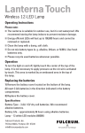
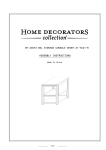
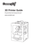
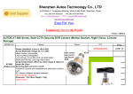
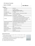
RoHS Specification Client Name: Client P/N: Factory P/N: HL-A-3528H308W-S1-13 OF-SMD3528WN Sending Date: Client approval Approval Audit Hong li approval Confirmation Approval Audit 殷小平 □ Qualified □ Unqualified Confirmation 王佩 DATE: Adr:West side of Dongfeng Highway,Auto City,Huadu District,Guangzhou,China Tel:020-86733333(Switchboard) Fax:020-86733883 86733938 86733265 Web:www.honglitronic.com SPEC NO:B-10-A-0195 REV NO: A/2 DATE: DEC/21/2010 PAGE: 1 OF 9 HL-A-3528H308W-S1-13 Features PLCC-2 Package. Extremely Suitable Available Moisture wide viewing angle for all SMT assembly and solder process on tape and reel sensitivity level: Level 4 Package:2000pcs/reel RoHS compliant Description The White LED which was fabricated using a blue chip and the phosphor Applications ■ Optical indicator ■ Indoor display ■ Interior automotive lighting ■ Backlight for LCD, switch and Symbol, display ■ Light pipe application ■ General use Recommended Soldering Package Dimensions 3.50 [0.14] 1 2 2 .4 0 [0 .0 9 ] 2 .5 0 [0 .1 0 ] 2 .8 0 [0 .1 1 ] 3.20 [0.13] 3.70 [0.15] 1.70 [0.07] 0.80 [0.03] 2.40 [0.09] 0 .7 0 [0 .0 3 ] 1 .4 0 [0 .0 6 ] POLARITY MARK 1.00 [0.04] 1 2 2 1 Notes: 1. All dimension units are millimeters. 2.All dimension tolerance is ±0.15mm unless otherwise noted. SPEC NO:B-10-A-0195 REV NO: A/2 DATE: DEC/21/2010 PAGE: 2 OF 9 HL-A-3528H308W-S1-13 Selection Guide Dice Part No. HL-A-3528H308W-S1-13 OF-SMD3528WN Lens Type WHITE (InGaN ) Yellow Diffused Luminous intensity (mcd) @ 20mA Luminous flux(lm) @ 20mA Viewing Angle Min. Typ. Min Typ 21/2 2050 2400 6.8 7.3 120° Note: 1. 1/2 is the angle from optical centerline where the luminous intensity is 1/2 the optical centerline value. 2.the above luminous intensity measurement allowance tolerance ±10%. Electrical / Optical Characteristics at Ta=25°C Parameter Symbol Min. Typ. Max. Units Test Conditions Forward Voltage VF 2.8 -- 3.4 V IF=20mA Reverse Current IR -- -- 10 μA VR = 5V X -- 0.32 -- -- IF=20mA Y -- 0.33 -- -- IF=20mA Color Temperature Tc -- 6000 -- K IF=20mA Color Rendering Index CRI 65 -- -- Ra IF=20mA Color Coordinates Absolute Maximum Ratings at Ta=25°C Parameter Symbol Rating Units Power Dissipation Pd 105 mW DC Forward Current IF 30 mA Peak Forward Current [1] IFP 100 mA Reverse Voltage VR 5 V Electrostatic Discharge (HBM) ESD 1000 V Operating Temperature Topr -40 ~ +85 ℃ Storage Temperature Tstg -40 ~ +100 ℃ Note: 1.1/10 Duty Cycle, 0.1ms Pulse Width. 2.The above forward voltage measurement allowance tolerance ±0.1V 3.The above color temperature measurement allowance tolerance ±0.003 SPEC NO:B-10-A-0195 REV NO: A/2 DATE: DEC/21/2010 PAGE: 3 OF 9 HL-A-3528H308W-S1-13 Typical optical characteristics curves Ambient Temperature VS. Forward Current Forward Current VS. Relative Intensity 60 Relative Luminous Intensity 2.5 Forward Current(mA) 50 40 30 20 10 0 2.0 1.5 1.0 0.5 0.0 0 20 40 60 80 Ambient Temperature 100 0 10 Ta(℃) 20 30 40 50 Forward Current(mA) Ambient Temperature VS. Relative Intensity Forward Voltage VS. Forward Current 3.0 Relative Luminous Intensity Forward Current(mA) 40 30 20 10 0 0 1 2 3 2.5 2.0 1.5 1.0 0.5 0.0 4 -40 Forward Voltage(V) -20 0 20 Ambient Temperature 40 60 80 Ta(℃) Diagram characteristics of radiation Relative spectral emission Relative luminous intensity 1.0 0.8 0.6 0.4 0.2 0.0 380 460 540 620 700 780 Wavelength(nm ) SPEC NO:B-10-A-0195 REV NO: A/2 DATE: DEC/21/2010 PAGE: 4 OF 9 HL-A-3528H308W-S1-13 CIE Chromaticity Diagram 0.38 C5-1-1 0.36 C4-1 C5-2-1 C4-2 C4-3 C3-1 0.34 C4-4 C3-2 C4-5 C3-3 C5-4-1 C5-5-1 C5-6-1 C4-6 C3-4 0.32 C5-3-1 C3-5 C3-6 0.30 0.30 C3-1 0.31 0.32 6000-6500K C3-2 0.33 6000-6500K 0.34 C3-3 6000-6500K X 0.3112 0.3209 0.3213 0.3120 X 0.3120 0.3213 0.3217 0.3127 X 0.3127 0.3217 0.3221 0.3136 Y 0.3408 0.3498 0.3440 0.3354 Y 0.3354 0.3440 0.3382 0.3299 Y 0.3299 0.3382 0.3317 0.3237 C3-4 6000-6500K C3-5 6000-6500K C3-6 6000-6500K X 0.3136 0.3221 0.3226 0.3144 X 0.3144 0.3226 0.3229 0.3151 X 0.3151 0.3229 0.3232 0.3157 Y 0.3237 0.3317 0.3251 0.3174 Y 0.3174 0.3251 0.3198 0.3124 Y 0.3124 0.3198 0.3145 0.3074 C4-1 5700-6000K C4-2 C4-3 5700-6000K 5700-6000K X 0.3206 0.3274 0.3275 0.3209 X 0.3209 0.3275 0.3277 0.3213 X 0.3213 0.3277 0.3278 0.3217 Y 0.3554 0.3615 0.3556 0.3498 Y 0.3498 0.3556 0.3496 0.3440 Y 0.3440 0.3496 0.3436 0.3382 C4-4 5700-6000K C4-5 5700-6000K C4-6 5700-6000K X 0.3217 0.3278 0.3280 0.3221 X 0.3221 0.3280 0.3281 0.3226 X 0.3226 0.3281 0.3283 0.3229 Y 0.3382 0.3436 0.3369 0.3317 Y 0.3317 0.3369 0.3302 0.3251 Y 0.3251 0.3302 0.3247 0.3198 C5-1-1 5500-5700K C5-2-1 5500-5700K C5-3-1 5500-5700K X 0.3274 0.3326 0.3326 0.3275 X 0.3275 0.3326 0.3326 0.3277 X 0.3277 0.3326 0.3326 0.3278 Y 0.3615 0.3660 0.3599 0.3556 Y 0.3556 0.3599 0.3538 0.3496 Y 0.3496 0.3538 0.3477 0.3436 C5-4-1 5500-5700K C5-5-1 5500-5700K C5-6-1 5500-5700K X 0.3278 0.3326 0.3325 0.3280 X 0.3280 0.3325 0.3325 0.3281 X 0.3281 0.3325 0.3324 0.3283 Y 0.3436 0.3477 0.3409 0.3369 Y 0.3369 0.3409 0.3340 0.3302 Y 0.3302 0.3340 0.3283 0.3247 SPEC NO:B-10-A-0195 REV NO: A/2 DATE: DEC/21/2010 PAGE: 5 OF 9 HL-A-3528H308W-S1-13 Reliability Test Items And Conditions The reliability of products shall be satisfied with items listed below. Confidence level :90% LTPD :10% No. Items Ref.Standard 1 Reflow JESD22-B106 Test Condition Test Hours/ Cycles Sample Size Ac/Re 3 times. 22Pcs. 0/1 Temp:260℃max T=10 sec 2 Temperature Cycle JESD22-A104 100℃±5℃ 30 min. ↑↓5 min -40℃±5℃ 30 min. 100 Cycles 22Pcs. 0/1 3 Thermal Shock JESD22-A106 100℃±5℃ 5 min. ↑↓ -40℃±5℃ 5 min. 100 Cycles 22Pcs. 0/1 4 High Temperature Storage JESD22-A103 Temp:100℃±5℃ 1000Hrs. 22Pcs. 0/1 5 Low Temperature Storage JESD22-A119 Temp:-40℃±5℃ 1000Hrs. 22Pcs. 0/1 6 DC Operating Life JESD22-A108 1000Hrs. 22Pcs. 0/1 1000Hrs. 22Pcs. 0/1 Ta=25℃±5℃ IF=20mA High Temperature 7 JESD22-A101 High Humidity 85℃±5℃/ 85%RH IF=5mA *The technical information shown in the data sheets are limited to the typical characteristics and circuit examples of the referenced products. It does not constitute the warranting of industrial property nor the granting of any license. SPEC NO:B-10-A-0195 REV NO: A/2 DATE: DEC/21/2010 PAGE: 6 OF 9 HL-A-3528H308W-S1-13 SMT Reflow Soldering Instructions 1.Reflow soldering should not be done more than two times 2.When soldering , do not put stress on the LEDs during heating Soldering iron 1.When hand soldering, the temperature of the iron must less than 300℃ for 3 seconds 2.The hand solder should be done only one times Repairing Repair should not be done after the LEDs have been soldered. When repairing is unavoidable, a double-head soldering iron should be used (as below figure). It should be confirmed beforehand whether the characteristics of LEDs will or will not be damaged by repairing. Cautions The encapsulated material of the LEDs is silicone. Therefore the LEDs have a soft surface on the top of package. The pressure to the top surface will be influence to the reliability of the LEDs. Precautions should be taken to avoid the strong pressure on the encapsulated part. So when use the picking up nozzle, the pressure on the silicone resin should be proper. SPEC NO:B-10-A-0195 REV NO: A/2 DATE: DEC/21/2010 PAGE: 7 OF 9 HL-A-3528H308W-S1-13 Handling Precautions Compare to epoxy encapsulant that is hard and brittle, silicone is softer and flexible. Although its characteristic significantly reduces thermal stress, it is more susceptible to damage by external mechanical force . As a result, Special handling precautions need to be observed during assemble using silicone encapsulated LED products, Failure to comply might leads to damage and premature failure of the LED. 1.Handle the component along the side surface by using forceps or appropriate tools; do not directly touch or Handle the silicone lens surface, it may damage the internal circuitry. 3528 2.The outer diameter of the SMD pickup nozzle should not exceed the size of the LED to prevent air leaks. The inner diameter of the nozzle should be as large as possible. A pliable material is suggested for the nozzle tip to avoid scratching or damaging the LED surface during pickup. The dimensions of the component must be accurately programmed in the pick-and-place machine to insure precise pickup and avoid damage during production. 3.Do not stack together assembled PCBs containing LEDs. Impact may scratch the silicone lens or damage the internal circuitry 4.Not available in the situation of acidity for PH <PH7 5.LED operating environment and sulfur element composition cannot be over 100PPM in the LED mating 6.When we need to use external glue for LED application products, please make sure that the external glue matches the LED packaging glue. Additionally ,as most of LED packaging glue is silica gel, and it has strong Oxygen permeability as well as strong moisture permeability; in order to prevent external material from getting into the inside of LED, which may cause the malfunction of LED, the single content of Bromine element is required to be less than 900PPM,the single content of Chlorine element is required to be less than 900PPM,the total content of Bromine element and Chlorine element in the external glue of the application products is required to be less than 1500PPM 7.Other points for attention, please refer to our LED user manual. SPEC NO:B-10-A-0195 REV NO: A/2 DATE: DEC/21/2010 PAGE: 8 OF 9 HL-A-3528H308W-S1-13 Label IV: Luminous intensity rank VF: Forward voltage rank X/Y:Coordinate rank TC: Color temperature Polarity Mark 3.50±0.05 4.00±0.1 8.00±0.1 2.00±0.05 0.26±0.05 1.75±0.1 TAPE 1.50 +0.1 Tape Specifications (Units : mm) Top Tape 2.05±0.1 Reel Dimensions Moisture Resistant Packaging Note: The tolerances unless mentioned is ±0.1mm , Unit: mm SPEC NO:B-10-A-0195 REV NO: A/2 DATE: DEC/21/2010 PAGE: 9 OF 9