1
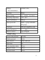
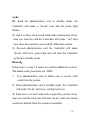
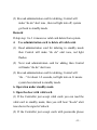
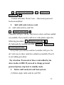
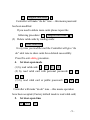
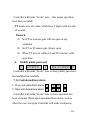
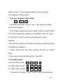
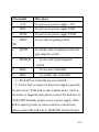
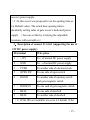
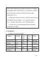
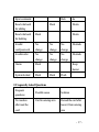
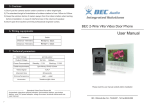
Single-Gate Access Control
User Manual
Please read this manual
before using the system.
V1.0(2012)
1. Product description:
The Single-Gate Access Control (Abb. Control) made by
our company is a high integrated, high capability and high
reliability system. It’ the best cost performance single gate
access control in this area.
Main functions and characters as below:
1 .has external only root card reader
2. Support administration card
3. Open (Close) the door continuously
4. Interlock between doors
5 Data copy (option)
6. High speed card recognize and process. It can feedback
2000pcs cards within 0.1s.So far this feature is the most
advanced on the Access market.
7. Controller hardware has special voltage detection circuit
and hardware watchdog circuits with assistant software dog in
internal software. So it has strong anti-interference capability
and high reliability.
2. Parameter:
-2-
Voltage
12VDC±10%
(Recommendation)
Currency
80mA
Relay loading
3A 24VDC, 3A/110VAC
Operating temperature
-20℃~60℃
Valid Card Volume
800 pcs
Open passwords
Public: a group; Individual:
800 groups
Card type
EM and compatibles cards
Card read distance
5
Read to connect
1pcs of Wgn26
— 8cm
3. Default setting
System edit password
123456
Public password
1234
Open manner
Only valid card
Open time
1s
Anti-demolition alarm
Close
Magnetic alarm
Close
Interlock check
Close
-3-
Magnetic alarm delay
0s
JP1,JP2 jump
Short 2,3
4. Restore factory settings (Initialization parameters)
1.
Remove the Controller’s front cover after power off
2.
Power off and keep press RESET key for 3s
3.
After heard the voice of ―do‖ this means system goes into
initiation. (At this time the Controller will restored all
the above parameters to original factory settings. The
initialization state will last for 8 seconds.
5. Administration card
1. Set administration card
Read 2pcs cards within 8s after successfully go into
initialization state( you will hear the voice of ―do do‖ for
twice). The first card is administration card for adding while
the second is for deleting. System will switch to standby
automatically after read two cards. If there is no card be read
after 8s of initialization the controller will switch into standby
automatically.
2. Use administration card to add one or several valid
-4-
cards.
(1). Read the administration card in standby mode; the
Controller will make a ―do-do‖ tone and the green light
flashes.
(2) read 1 to Npcs of non-used valid cards continuously. Every
time you read the card the Controller will make ― do‖ alert
tone show that card have successfully added into system.
(3) Re-read administration card the Controller will make
―do-do‖ alert tone, green light turn off, then the Controller
get back to standby mode.
Remark:
If skip step 1 to step 3 it means no card has added into system;
The added cards’ passwords are ―0000‖.
3
Use administration card to delete one or several valid
cards from the system.
(1) Read administration card in standby mode, the Controller
will make ―do do‖ alert tone, red light turns on.
(2) Read one or several valid cards accepted by system. Every
time you read the card your will hear ―do do‖ alert tone means
cards have deleted from the system successfully.
-5-
(3) Re-read administration card for deleting, Control will
make ―do do‖ alert tone , then red light turn off, system
get back to standby mode.
Remark:
If skip step 1 to 3 it means no valid card delete from system.
4.
Use administration card to delete all valid cards
(1) Read administration card for deleting in standby mode
then Control will make ―do do‖ alert tone, red light
flashes.
(2) Next read administration card for adding then Control
will make ―do do‖ alert tone
(3) Re-read administration card for deleting, Control will
―do…‖ for about 1-2 seconds, red light turn on. It means
system has returned to standby mode.
6. Operation under standby mode.
1. Open the door with valid card.
(1) If the Controller just accept valid cards you can read the
valid card in standby mode, then you will hear ―do-do‖ alert
tone shows the signal of unlock.
(2) If the Controller just accept cards with passwords please
-6-
read the valid card in standby mode. After heard the ―do-do‖
tone please input 4 digits personal passwords within 8s. You
will hear ―do-do‖ alert tone shows the signal of unlock.
(3) If the Controller just accepts cards or passwords you can
read the valid card or input 4 digits public passwords. Then
you will hear ―do-do‖ alert tone shows the signal of unlock.
2. Change personal passwords
Read valid card
Input 4 digits original passwords #
Input 4 digits new password within 8s after the door open
Re-input the 4 digits new passwords #
The Controller will make ― do-do‖ alert tone to tell you that
the passwords has been changed successfully.
Remark: This can be useful only for the mode is valid card
with passwords.
3. Go into edit mode:
Input *
6 digits system edit password
#
Control will remind ―do do‖, then yellow light on-- this means
system goes to editmode.
7. Keyboard operation under edit mode.
1. Change edit password
-7-
0
6 digits new password
password
#
repeat new
#
Control will make ―do do‖ tone —this means password
has been modified
2.
Add valid cards (release card)
(1) Add valid cards by card NO.
1
8digital card code
#
Controller will give ―do do‖ alert tone to show card have added
successfully. If you need to add more cards please repeat the
following procedure: 1
8digital card code
(2) Add cards by reading the cards:
Input 1
#
read one to
several unused cards
Every time you read the card the Controller will give ―do
do‖ alert tone to show cards have added successfully. Press #
to exit adding procedure.
Pay attention: Passwords of those cards added by the
above modes is 0000. If you need to change personal
password please step back to standby mode.
3.
Delete valid card(exit card from system)
(1) Delete single valid cards by card NO.
-8-
2
8digital card code
#
Controller will make ―do do‖ tone —this means password
has been modified
If you need to delete more cards please repeat the
following procedure: 2
8digital card code
#
(2) Delete valid cards by reading cards:
2
read valid card
Every time you read the card the Controller will give ―do
do‖ alert tone to show cards have deleted successfully.
Press # to exit adding procedure.
4.
Set door-open mode
(1) by read valid card: 3
0
0
#
(2) by read valid card with personal password: 3
1
0
#
(3) by read valid card or public password: 3
0
#
Controller will make ―do do‖ tone —this means operation
have been accepted.( Factory default mode is read valid card)
5.
Set door-open time
4
TT
#
-9-
2
Controller will make ―do do‖ tone —this means operation
have been accepted.
TT means new set value, which have 2 digits with the unit
of second.
Remark:
(1) Set TT as o means gate will not open at any
condition.
(2) Set TT as 99 means gate always open.
(3) When TT was set within 01 and 98 it means valid
open time.
6.
Modify public password.
5
4 位新密码
#
重复 4 位新密码
#
Controller will make ―do do‖ tone to show public password
has modified successfully.
7. Set Anti-demolition Alarm
1. Close anti-demolition alarm: 6
0
0
#
2. Open anti-demolition alarm: 6
0
1
#
Controller will make ―do do‖ tone to show operation has
been accepted. When 0pen anti-demolition alarm, such as
when the case was open Controller will make continuous
- 10 -
alarm ―do-do..‖ Then output terminal on J2 will export
low-frequency alarm signal.
8 Set gate magnetic alarm delay
7
TT
#
Controller will make ―do do‖ tone —this means operation
have been accepted.
TT is 2 digits alarm delay time with the unit of second. When
TT is 00 it means gate magnetic is forbidden; when TT value
is between 01 and 99 it means gate magnetic is open.
Remark:
After start this function Controller will make continuous alarm
in following conditions
1 forgot closing the door after opening the door in normal
state;
2. door was not opened through the Controller.
9. Set safety mode.
(1)Close safety mode:
8
0
0
#
(2) Open safety mode1: 8
0
1
#
(3) Open safety mode2: 8
0
2
#
Controller will make ―do do‖ tone to show your operation
- 11 -
have been accepted.
Safety mode1: read 10 void cards continuously or input wrong
password for 10 times system will be locked for 10mins.(In
this case keyboard was forbidden and no card can be read)
Safety mode2: read 10 illegal cards continuously or input
wrong password for 10 times alarm terminal on J2 will export
low-frequency alarm signal while Buzzer will continue to
tweet (alarm can be released by inputting valid password and
read valid card)
10 Interlock check setting
(1) Close interlock check:
(2)Open interlock check: 9
9
0
0
0
1
#
#
Controller will make ―do do‖ tone to show your operation
have been accepted.
If interlock check is closed Controller will follow the
instruction to open the door whether gate magnetic is open or
not. On the contrary only gate magnetic is closed (the door is
closed) Controller can follow the instruction to open the door.
11. Exit edit mode
Press
﹡ Controller will make ―do do‖ tone, yellow light
- 12 -
turn off and Controller return to standby mode.
12. Remarks for editing:
(1) In edit mode if there is no edit command in 20s
Controller will switch to standby mode automatically.
(2) If a certain command is not input entirely such as user
found incorrect command has input she (he) can press *
to
revoke the command.
(3). Add the 8 digits card NO. mentioned in command of
adding valid card (add card into system) or deleting valid card
( delete card from system) as the late 8 digits NO. of the serial
NO. printed on the card. Please input the 8 digits completely
(Do not ignore 0 in front of those 8 digits card NO. )
8. Installation and Wiring
1. Installation
Remove screw between back and cabinet, fix back to
entrance wall with slugs and screws.
Attention: forbid operation with power on.
2. J1 connection description (use the dedicated
power supply especially for gate access)
- 13 -
J1 terminal
Wire place
1 — +12V
To gate access power supply +12V
2 — GND
To gate access power supply GND
3 — PUSH
To gate access power supply PUSH
5 — OPEN
To one side of opening switch
SW
6 — DGND
To another side of opening switch and
gate magnetic switch
7 — DOOR IN
To one said of gate magnetic
switch
8 — BELL
To one side of doorbell
9 — BELL
To another side of doorbell
(1)JP1& JP2 on Controller are set to default.
(2)Power lock is connect to the power supply especially
for gate access. If the lock is open without power (such as
electronic or magnetic lock) please connect the lead wire to
NC& GND terminals of gate access’s power supply. If the
lock is open by power on (such as electric control lock)
please connect the lead wire to NO&GND terminal of gate
- 14 -
access’s power supply.
(3)In this case it was proposed to set the opening time as
1s(.Default value). The actual door-opening time is
decided by setting value of gate access’s dedicated power
supply. (You can set this by revolving the adjustable
resistance with screwdriver).
3、Description of connect J1 wire1 (supporting the use of
12V DC power supply)
J1terminal
Wire place
1 — +12V
To+ of normal DC power supply
2 — GND
To – of normal DC power supply
3 — PUSH
To another side of electronic lock
5 — OPEN SW
To one side of open switch
6 — DGND
To another side of opening switch
and gate magnetic switch
7 — DOOR IN
To one said of gate magnetic switch
8 — BELL
To one side of doorbell
9 — BELL
To another side of doorbell
(1)JP1& JP2 on Controller are set to 2-3 default. If the
- 15 -
lock is open without power (such as electronic or magnetic
lock) please short connect JP1 to 1-2..If the lock is open by
power on (such as electric control lock) please short
connect JP1 to 2-3.
(2)One side of electronic lock is connect to positive pole
of normal DC power supply(or J1’s positive pole of
12V).Another side connect to J1’s PUSH terminal
(3)In this case the actual opening time is decided by
Controller’s set value.
9. Attachment
1.
Introduce for sound and light
Condition
Red light
Green
Yellow
light
light
On
Buzzer
First Power on
on
On
Initiation
flash
flash
Do(long)
Standby mode
On
Normal Unlock
On
On
Do(long)
Edit Mode
On
Do(long)
Du du
- 16 -
Input command
flash
Read valid card
Flash
du
Du du
for adding
Read valid card
Flash
Du du
for deleting
Invalid
No
No
No
card/password
change
change
change
Invalid order
No
No
No
change
change
change
Alarm
Flash
Du dudu
Du dudu
Keep
buzzer
System locked
Flash
Flash
Flash
2. Frequently Asked Questions
Frequent
questions
No reaction
Possible cause
Solution
Card in sensing area
Reread the card after
after read the
leave it from sensing
card
area
- 17 -
Indicator does
Card problem
Change card
Power input failure
Check power supply
not light on
or wiring
Insufficient power
Change high current
Door doesn’t
supply
power supply
open in normal
Gate is set to normally
Set for 1-98s.
operation
closed
Electronic lock failure
Change lock
Gate access control’s
Close back cover or
back cover opened
anti-demolition alarm
and anti-demolition
Door keep
alarm is set effectively
buzzer
Gate magnetic alarm
Close the door or gate
been touched and it
magnetic alarm.
has been set
effectively
Card can not be
Card been authorized
authorized
repeatedly or
properly
authorized cards
- 18 -
quantity is out of
range
3. Reference
(1) When you need to read the card for entering& exiting
please connect only-root reader’s D0、D1、GND、V12 to J2’s
corresponding terminals.
(2) In case of forgetting the password you can initialize the
system; if forgot personal password you can delete the card
and add it once again so as to change personal password.
(3) Users who need more card capacity or functions over the
manual they can choose other models in this series.
10. After-sales service.
Thank you for using our products. To ensure your legal
rights and avoid your worries please read the following
after-sales content and provide valuable comments and
suggestions:
(1) Our company's products have free warranty service since
- 19 -
the date of __ months after sale. After warranty period we
need to charge for the cost. This is depending on the
particular fault condition.
(2) Repair products should be packed properly before
delivering. Our company will not be responsible for damage
or loss in transportation process.
(3) In free warranty period, damage or product failure caused
by improper use; burning accident cause by external electric
shock or improper installation; damage caused by
non-maintenance service provider’ s overhaul or repair, or
damage of product label, etc., our company is entitled to
denial service or charge for the cost and service.
11. Packing list
Mounting screws and rubber plug
Manual
Gate Access Controller
6Pin socket line
1package
1set
1set
1pcs
- 20 -