1
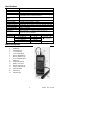
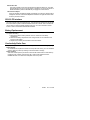
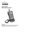
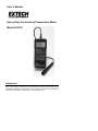
User's Manual
Heavy Duty Conductivity/Temperature Meter
Model 407303
Introduction
Congratulations on your purchase of Extech’s Conductivity/ Temperature Meter. This meter
offers a dual display of Conductivity and Temperature, Conductivity Cell calibration adjust,
Auto/Manual temperature compensation, and a RS-232 PC Interface. This professional
meter, with proper care, will provide years of safe reliable service.
Specifications
Circuit
Display
Measurements
Data hold
Sensor Structure
Temp. compensation
adjust
Data recording
Auto Power OFF
PC Interface
Operating conditions
Power Supply
Power Consumption
Weight
Dimensions
Measurement
Conductivity
Temperature
Custom LSI microprocessor circuit
Dual function 0.5" (13mm) 1999 count LCD w/ contrast adjust
Conductivity in µS and mS; Temperature oC/F
Freezes displayed value
Remote Conductivity Sensor: Carbon rod type
Temperature sensor: Precision thermistor
0 to 5% per °C over the range of 32 to 140°F (0 to 60°C)
Record the Min/Max/Avg readings for later recall
Automatic power off after 10 minutes
RS 232 serial data output
Temperature: 32°F to 122°F (0°C to 50°C); Humidity <80% RH
9V battery
Approx. 7.8 mA DC
0.77 lbs (350 g) (including batteries & probe)
Main instrument: 7.1 x 2.8 x 1.3" (180 x 72 x 32 mm)
Probe: 0.87" (22 mm) diameter
Range
0.1 to 199.9 µS
0.2 to 1.999 mS
2 to 19.99 mS
32 to 140°F (0 to 60 °C)
Resolution
0.1 µS
0.001 mS
0.01 mS
0.1°C / 0.1 °F
Accuracy
+ (3% F.S. + 1d)
(after calibration)
+0.8 °C / 1.5 °F
Meter Description
1
2
3
4
5
6
7
8
9
10
11
12
13
14
15
16
LCD Display
POWER key
Data "HOLD" key
°C/ F" Select key
LCD Contrast adjust
Memory "RECORD" key
Memory "RECALL" key
Temp Coefficient adjust
Range key
Temp Coefficient key
Battery cover (rear)
RS-232 output jack (to
Sensor input socket (to
Electrode handle
Electrode tip
Electrode plug
2
407303
Ver 1.6 03/01
Operation
Preparation for use
1. Install the sensor plug into the sensor's input socket.
2. Press the Power key to turn on the meter.
3. Select the temperature units by pressing the C/ F key. The display will indicate
C or F as selected.
4. Select the Conductivity units by pressing the Units key.
Conductivity Calibration
The Conductivity probe calibration should be performed frequently to minimize
measurement errors.
1. Remove the battery from the battery compartment to gain access to the
calibration adjustments. Refer to the diagram below.
2. Prepare a standard conductivity solution of a value close to the value of the
solution to be tested.
3. Place the probe into the calibration solution and adjust VR4 until the meter
reads the correct value. Other VR pots are for factory use only. Do not adjust.
Battery Compartment
View from bottom of meter
VR4
Temperature Compensation
The unit defaults to a 2% per oC temperature compensation factor. To manually
change the coefficient factor, follow the steps below:
1. Set the meter to the 200 µS range via the Units key.
2. Press the TEMP key
3. Press the Factor Adjust key to select the desired compensation factor (in
increments of 0.1 % per degree C).
4. Once the desired factor is set, press the TEMP key again.
Range Select
1. If the display shows “-------“, the meter is in an overange condition. Press the
range key to select a higher range
2. If the display shows “_____“, the meter is in an underrange condition. Press the
range key to select a lower range
Data Hold
Press the Data Hold key to freeze the displayed value. The LCD will display DH for
Data Hold mode along with the held reading. Press the Hold key again to release
the data hold function.
MIN/MAX/AVG Data Recording
When selected, the Data Recording function records the Min, Max, and Average
readings. To start a data recording session:
1.
Press the RECORD key once. The REC indicator will appear on the display
and the meter will begin to record the lowest (min), highest (max), and
average (avg) readings.
2.
To recall the data, press the RECALL key once. The MAX indicator will
appear along with the highest reading recorded since the RECORD key was
pressed.
3.
Press the RECALL key again to view the MIN value.
4.
Press the RECALL key again to view the AVG reading.
5.
To exit the Record mode, press the RECORD key again. The display
indicators REC, MIN, MAX, and AVG will disappear.
3
407303
Ver 1.6 03/01
Auto Power OFF
The meter includes an Auto shut off feature that preserves battery life. The meter
will automatically turn off if no function button is pressed in any 10 minute period. To
disable this feature press the RECORD key to engage the record function.
LCD Contrast Adjust
It may be necessary to adjust the display contrast due to a change in viewing angle or
voltage drift. Use the LCD Contrast adjustment located on the right side of the meter
to set the preferred contrast.
RS-232 PC Interface
The meter includes a RS-232 serial data port. This interface was designed to operate with
the Extech Data Acquisition Software/Hardware kit Part No. 407000. This kit enables the
user to capture, store and display readings using a PC. For more information contact
Extech or refer to the 407000 User Manual for details.
Battery Replacement
The low battery indication LBT appears on the LCD when the battery runs low.
To replace the battery:
1. Remove the meter's rubber protective cover to access the rear battery
compartment.
2. Remove the battery compartment cover using a small coin or screwdriver and
remove the 9V battery.
3. Replace the 9V battery and reinstall the cover and holster.
Conductivity Probe Care
To prepare the probe for use, remove the outer protective sheath used during shipping.
Probe Storage
On sheathed cells, replace the sheath over the probe when storing. For non-sheathed
versions, keep the probe’s tip soaking in de-ionized water in storage
Probe Cleaning
After each use the probe tip should be rinsed with de-ionized water. If solids build up
inside the probe, carefully remove them with a cotton swab soaked in solvent.
Caution: Be sure not to touch the metal parts of the inner probe.
4
407303
Ver 1.6 03/01
Calibration and Repair Services
Extech offers complete repair and calibration services for all of the products we sell. For
periodic calibration, NIST certification or repair of any Extech product, call customer
service for details on services available. Extech recommends that calibration be performed
on an annual basis to insure calibration integrity.
Warranty
EXTECH INSTRUMENTS CORPORATION warrants this instrument to be free of defects in parts and
workmanship for 3 years from date of shipment (a six month limited warranty applies on sensors and
cables). If it should become necessary to return the instrument for service during or beyond the warranty
period, contact the Customer Service Department at (781) 890-7440 for authorization. A Return
Authorization (RA) number must be issued before any product is returned to Extech. The sender is
responsible for shipping charges, freight, insurance and proper packaging to prevent damage in transit.
This warranty does not apply to defects resulting from action of the user such as misuse, improper wiring,
operation outside of specification, improper maintenance or repair, or unauthorized modification. Extech
specifically disclaims any implied warranties or merchantability or fitness for a specific purpose and will not
be liable for any direct, indirect, incidental or consequential damages. Extech's total liability is limited to
repair or replacement of the product.
The warranty set forth above is inclusive and no other warranty, whether written or oral, is expressed or
implied.
Copyright © 2000 Extech Instruments Corporation. All rights reserved
including the right of reproduction in whole or in part in any form.
(
Tech Support Hotlines
781-890-7440 ext. 200
[email protected]
www.extech.com
5
407303
Ver 1.6 03/01