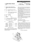
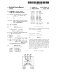
1
US007042441B2
(12) United States Patent
(10) Patent N0.:
Adams et al.
(54)
(75)
(45) Date of Patent:
INPUT DEVICE INCLUDING A SCROLL
WHEEL ASSEMBLY FOR MANIPULATING
AN IMAGE IN MULTIPLE DIRECTIONS
5,477,508 A
5,510,811 A
Inventors: Aditha M. Adams, Seattle, WA (US);
.
12/1995 Will
4/1996 Tobey et :11.
5,517,257 A
5/1996 Dunn et a1.
5/1996
5’530’455 A
6/1996 Gllhck
Imai et a1. ................ .. 345/167
6/1998 Wang
5 , 774 , 075 A ,,,
6/1998 Palalau
(US); Steven W. Fisher, Edmonds, WA
5 808 568 A
9/l998 Su
(US); Gino Garcia, Edmonds, WA
(US); Daan Lindhout, Seattle, WA
(US); Timothy Michael Muss, Seattle,
539103789 A
5,912,661 A
5,952,997 A
6/1999 Kim
6/1999 Siddiqui
9/1999 Hu
WA (US); Mark Newton, Bellevue, WA
5,956,018 A *
9/1999 Pejic et a1. ............... .. 345/157
(Us)
5,959,614 A *
9/1999
(73) Assignee: Microsoft Corporation, Redmond, WA
et a1.
.............. .. 341/35
H0 ........................... .. 345/167
(Continued)
(Us)
Notice:
May 9, 2006
5,521,617 A *
5,771,038 A
Steven N. Bathlche,
Redmond, WA
_
(*)
US 7,042,441 B2
FOREIGN PATENT DOCUMENTS
Subject to any disclaimer, the term of this
patent is extended or adjusted under 35
EP
U.S.C. 154(b) by 396 days.
1258019 B9
11/2002
(Continued)
OTHER PUBLICATIONS
(21) Appl. N0.: 10/183,993
Web page reviewing “Kensington TurboRing Trackball”;
(22) Filed:
Jun. 28, 2002
(65)
http://WWW.avault.com/hardWare/printi
Prior Publication Data
US 2005/0259077 A1
revieW.asp?revieWiturboring; publication date unknown,
but believed to be prior to Jun. 28, 2002.
Nov. 24, 2005
(Continued)
(51)
Int. Cl.
G09G 5/00
(52)
(58)
US. Cl. ..................... .. 345/163; 345/157; 345/164
Field of Classi?cation Search ...... .. 345/l56il69,
(2006.01)
345/784, 785, 786, 787; 200/5 A, 6 A; 348/734;
7l5/784i787; 463/37i38; 273/148 B
See application ?le for complete search history.
(56)
Primary ExamineriLun-yi Lao
(74) Attorney, Agent, or FirmiBanner & WitcoiT, Ltd.
(57)
ABSTRACT
A scroll Wheel assembly includes a rotatable member.
Encoded rotation of the rotating member causes scrolling of
References Cited
an image on a display screen along an axis. An actuator is
located Within the rotational member. Pressure on different
U.S. PATENT DOCUMENTS
parts of the actuator causes scrolling of the image in oppos
ing directions along a second axis. Pressure upon additional
4,712,101 A
4,720,703 A
12/1987 Culver
l/l988 Schnarel, Jr. et 31.
parts of the actuator can provide additional screen functions.
5,063,289 A *
11/1991
rotatable member or actuator may also be programmable.
Jasinski et a1. ........... .. 250/221
5,235,868 A
8/1993 Culver
5,404,152 A *
4/1995
5,446,481 A
8/1995 Gillick et a1.
Functions and commands caused by manipulation of the
Nagai ....................... .. 345/157
15 Claims, 10 Drawing Sheets
US 7,042,441 B2
Page 2
Web page for Kid TRAC User’s Manual; http://www.
US. PATENT DOCUMENTS
5,963,197
6,075,518
6,075,575
6,097,371
6,097,372
D431,037
6,128,006
6,132,118
6,188,393
A
A
A
A
A
S
A
A
B1
microspeed.com/pages/supports/manuals/kidtracmhtml;
10/1999 Bacon et a1.
6/2000 Pruchniak
6/2000 Schein et a1.
publication date unknown, but believed to be prior to Jun.
28, 2002.
8/2000
8/2000
9/2000
10/2000
10/2000
2/2001
Mouse;
Web page for “Ateck” A4 RFW-33 Radio Wireless PS/2
Siddiqui et a1.
Suzuki
Varga et a1.
Rosenberg et a1.
GreZesZak
Shu
6,198,473 B1*
3/2001
6,204,838 B1
6,281,881 B1
3/2001 Wang
8/2001 Siddiqui et a1.
to be prior to Jun. 28, 2002.
Web page for “Sakar Yahoo! 4D Internet Scroll Mouse” and
“Sakar Optical Mouse w/ Email alert Metallic Silver (U SB)”;
Armstrong ................ .. 345/163
6,300,939 B1 *
10/2001
6,323,844 B1
6,337,679 B1
11/2001 Yeh et a1.
1/2002 Chou
Decker et a1. ............ .. 345/157
6,340,800 B1*
1/2002 Zhai et a1. ................ .. 200/5 R
1/2002 Wang et a1.
2/2002 Smith
3/2002 Long
6,359,611 B1*
3/2002
6,380,927 B1
4/2002 Ostrum et a1.
6,424,355 B1*
7/2002 Watanabe et a1. ......... .. 345/668
6,519,003
2/2003
Chan ........................ .. 345/156
... .. ... ..
and iTrackballs/; publication date unknown, but believed to
be prior to Jun. 28, 2002.
Web page for “ICONCEPTS 70152”; http://www.panwebi.
unknown, but believed to be prior to Jun. 28, 2002.
Web page for “Yahoo 8D Internet Mouse”; http://www.
panwebi.com/products/computer/mouse/8dinternetmouse.
6,353,429 B1
Swayze
http://www.slarp.com/products/InputiDevices/Micei
com/products/computer/mouse/70152.htm; publication date
6,340,966 B1
6,348,912 B1
B1*
http://www.shop.store.yahoo.com/4itech/
a4rfradwirps.html; publication date unknown, but believed
. . . ..
348/375
htm; publication date unknown, but believed to be prior to
Jun. 28, 2002.
“Photo A”: photograph of scroll wheel from LOGITECH
cordless optical mouse, P/N 851497-0000; date of ?rst
availability and/ or disclosure prior to (or believed to be prior
6,522,321 B1
2/2003 Chen et a1.
to) application ?ling date.
6,534,730 B1 *
3/2003
6,570,108 B1
6,608,616 B1
5/2003 Lin
8/2003 Lin
“Photo B”: photograph of scroll wheel from LOGITECH
cordless optical mouse, P/N 851497-0000; date of ?rst
availability and/ or disclosure prior to (or believed to be prior
6,697,050 B1 *
6,809,275 B1
2002/0149566 A1*
Ohmoto et a1. .............. .. 200/4
2/2004
Shinohe et a1. ........... .. 345/163
10/2004 Cheng et a1.
10/2002
Sarkissian ................. .. 345/168
2003/0025673 A1
2/2003 Ledbetter et a1.
2003/0076303 A1*
2003/0095096 A1*
4/2003
5/2003
2003/0107547 A1
2004/0001042 A1
6/2003 Kehlstadt et a1.
1/2004 Lindhout et a1.
Huppi ...................... .. 345/163
Robbin et a1. ............ .. 345/156
2004/0051392 A1*
3/2004
2004/0150623 A1
8/2004 Ledbetter et a1.
2005/0104854 A1*
5/2005
to) application ?ling date.
“Photo C”: photograph of scroll wheel from mouse
manufactured by A4tech Co., Ltd., Taipei, Taiwan; date of
?rst availability and/or disclosure prior to (or believed to be
prior to) application ?ling date.
“Photo D”: (second) photograph of scroll wheel from mouse
manufactured by A4tech Co., Ltd., Taipei, Taiwan; date of
Badarneh .................. .. 307/112
?rst availability and/or disclosure prior to (or believed to be
prior to) application ?ling date.
Su et a1. ................... .. 345/163
“Photo E”: photograph of scroll wheel from mouse
manufactured by KYE Systems, Taipei, Taiwan; date of ?rst
FOREIGN PATENT DOCUMENTS
availability and/ or disclosure prior to (or believed to be prior
JP
07-092939
JP
2000-200147
*
4/1995
to) application ?ling date.
7/2000
“Photo F”: photograph of scroll wheel frm RAZER
OTHER PUBLICATIONS
Web page reviewing “TurboRing”; http://www.macworld.
com/2000/10/reviews/turboring.html; publication date
“Boomslang” mouse, available from Kama LLC, Taiwan;
date of ?rst availability and/or disclosure prior to (or
believed to be prior to) application ?ling date.
<http://www.mside.net/microscrollii,html>
,
MSIDE.net,
unknown, but believed to be prior to Jun. 28, 2002.
Web page from “Van’ 5 Hardware”; http ://www.
vanshardware.com/reviews/200 1 /october/
2000.
011002iTurboRing/011002iTurboRing.htm;
Design-RollerBar Mousing Station-Optical Technology, 2
published
Oct. 2, 2001.
Web page reviewing “TurboRing”; http://www.keyalt.com/
pointdevices/turboring.htm; publication date unknown, but
believed to be prior to Jun. 28, 2002.
Web page for “Micro TRACTM ”; http://www.microspeed.
com/products/pd600s.html; publication date unknown, but
believed to be prior to Jun. 28, 2002.
Web page for “Kid TRAC ” model PD-280S; http://www.
microspeed.com/products/kidtrac.html; publication date
unknown, but believed to be prior to Jun. 28, 2002.
showing Micro Scroll II mouse from Micro, 2 sheets, Dec.
<http://www.contourdesign.com/rollerbar.htm>,
Contour
sheets, Jan., 2001 and 1 sheet press release dated Nov. 29,
2000.
<http://www.mousetrapper.dk>, Mouse Trapper product
description, 12 color sheets including original Danish
language and English translation as performed by Transla
tion Experts Ltd. Service, date of product release unknown
but prior to ?ling date of application.
U.S.App1. No. 10/158,996 ?led Jun. 3, 2002.
* cited by examiner
U.S. Patent
May 9,2006
Sheet 1 or 10
FIG. 1
US 7,042,441 B2
U.S. Patent
May 9,2006
Sheet 2 or 10
FIG. 2
US 7,042,441 B2
U.S. Patent
May 9, 2006
20
FIG. 3
Sheet 3 0f 10
US 7,042,441 B2
U.S. Patent
May 9,2006
Sheet 4 or 10
US 7,042,441 B2
26
24
28
\
22
32
FIG. 4
U.S. Patent
May 9, 2006
Sheet 5 0f 10
US 7,042,441 B2
26
52
i
I
I 1:”
Z
imam/7d‘: '''''''''''''''''' “
1111/1/11;/I
Z
24
22
32
FIG. 5
U.S. Patent
May 9, 2006
Sheet 6 0f 10
FIG. 6
US 7,042,441 B2
U.S. Patent
May 9,2006
Sheet 7 or 10
FIG. 7
US 7,042,441 B2
U.S. Patent
May 9, 2006
Sheet 8 0f 10
US 7,042,441 B2
.UEw
Nu
U.S. Patent
May 9, 2006
Sheet 9 0f 10
US 7,042,441 B2
171
FIG. 9A
U.S. Patent
May 9, 2006
Sheet 10 0f 10
US 7,042,441 B2
122
FIG. 9B
171
EH54
UUU
FIG. 9C
175
FIG. 9D
US 7,042,441 B2
1
2
INPUT DEVICE INCLUDING A SCROLL
WHEEL ASSEMBLY FOR MANIPULATING
AN IMAGE IN MULTIPLE DIRECTIONS
interface in the form of a horizontal scroll bar (usually
located near the bottom of the display), positioning the
cursor on the scroll bar, and then rotating the Wheel. Locat
ing the scroll bar can be very difficult for people With bad
eyesight, small display screens and/or poor hand-eye coor
dination. Using a horizontal scroll bar also requires a user to
shift his or her gaze from the portion of the document being
FIELD OF THE INVENTION
The present invention relates to an input device including
an assembly for moving an image in multiple directions on
a display screen. More particularly, the present invention
relates to a scroll Wheel assembly that, When part of a
peripheral or integral input device that is operatively con
vieWed, and then relocate that portion after horizontal scroll
ing. Even if the size of the horizontal scroll bar and/or the
screen resolution can be adjusted, the user must nevertheless
perform additional pointing tasks Which are more time
consuming and mentally intensive than simply rotating a
nected to a host computer, can move an image in multiple
axes relative to the display screen.
Wheel or pushing a button. Alternative graphically assisted
tools for horizontal scrolling (e.g., positioning a cursor over
BACKGROUND OF THE INVENTION
a horizontal scroll bar, selecting the scroll bar, and moving
the cursor) also require cursor repositioning, and have
The vieWable contents of a computer ?le, such as a text
similar draWbacks.
Microside Corporation of Miami, Fla. offers a “Micro
document, spreadsheet, digital photograph, Web page, or
other image rendered on a conventional display screen, may
possess a size exceeding the vieWable boundaries of the
display screen. To address this issue, an individual may
utilize a scrolling method to scroll the image relative to the
display screen. Scrolling, as used herein and as is knoWn in
the art, describes the movement of an image relative to a
display screen in a particular direction. For example, “scroll
Scroll II” mouse that permits a user to scroll an image in
20
25
ing doWn” generally describes moving the vieWable contents
multiple perpendicular directions. This mouse includes a
?rst rotatable Wheel for scrolling an image up and doWn, and
a second, separate rotatable Wheel for scrolling an image left
and right. The rotatable Wheels are oriented so they extend
and rotate in planes that are perpendicular to each other. The
tWo scroll Wheels are independently operable. HoWever, this
arrangement has drawbacks. The tWo Wheels take up limited
of a ?le (such as a text document or image) relative to a
space on the upper surface area on the mouse, Which could
display screen so as to produce an effect of moving doWn in
be used for supporting the hand of the user or for additional
the document or image. Similarly, the terms scroll up, scroll
left and scroll right relate to moving the vieWable contents
input keys. Further, the tWo Wheels are relatively small in
30
of a ?le relative to a screen so as to produce an effect of
size so as to accommodate both Wheels on the upper surface
of the mouse. The smaller sized scroll Wheels make the
moving a document or image up, left, and right, respectively.
scrolling more di?icult to control. Additionally, the location
The term scrolling as used herein also includes panning,
Which is the automatic and/or continuous scrolling of an
image, often in response to a single command or input.
Scroll Wheels have been provided on computer mice, and
have been used by computer operators to move an image on
a display screen. A scroll Wheel assembly typically includes
of the horizontal scroll Wheel can be inconvenient for
effective control. Further, With this design, it might be
35
dif?cult for some users to easily reach and manipulate both
of the Wheels.
Accordingly, there remains a need for improved input
devices facilitating scrolling in multiple directions.
a rotatable scroll Wheel and a sensor to measure and encode
rotation. Typically, the scroll Wheel is located Within a
housing of a mouse or other peripheral computer device. A
portion of the scroll Wheel protrudes upWardly out of an
40
The present invention alloWs a user to conveniently scroll
opening in the housing, and is rotated in order to vertically
scroll the image displayed on the screen. An example of a
mouse including a knoWn scroll Wheel assembly is described
in US. Pat. No. 5,912,661, entitled “Z-ENCODER
45
MECHANISM” Which is hereby fully incorporated by ref
erence.
In operation, a conventional scroll Wheel is normally
rotated about a transversely extending axis secured Within a
SUMMARY OF THE INVENTION
50
a screen image, in multiple directions, With simple thumb or
?nger movements. In one embodiment, the invention
includes a scroll Wheel assembly having a rotatable member
attached to a device for sensing and encoding rotational
motion. The encoded rotational motion in turn causes scroll
ing of an image on a display screen along an axis. Positioned
Within the rotatable member is an actuator that, in response
to pressure on different parts of the actuator, can scroll the
housing. An encoder Wheel is coupled to the scroll Wheel
image along a second axis. The scroll Wheel assembly can be
and rotates When the scroll Wheel rotates. As the scroll Wheel
is rotated, an encoder senses the rotation of the encoder
Wheel, and delivers a corresponding signal to a host com
puter. That signal can be used to move an image, as is knoWn
used in a mouse, in a keyboard, in a trackball, in an intemet
in the art and disclosed in US. Pat. No. 5,912,661. Notably,
this alloWs a user to scroll the image Without changing the
position of the mouse and/or the cursor, and instead only
requires rotating the scroll Wheel (versus the entire mouse or
other device) With a thumb or ?nger. HoWever, displayable
appliance, in a notebook computer, in a tablet computer, in
a pocket computer, in a Personal Digital Assistant, and in
55
Functions and commands corresponding to manipulation of
the actuator and/ or rotatable member may also be program
60
portions of spreadsheets and many other types of documents
and screen images are often Wider than the display screen,
and the user must also scroll horizontally across the screen
to see the entire ?le. When the user needs to move the image
horizontally across the display screen, the user must typi
other applications Where multidirectional scrolling is desired
or useful. Pressure upon additional parts of the actuator can,
in some embodiments, provide additional screen functions.
65
mable.
In one embodiment, the invention includes an input
device that is in communication With the display device
screen. The input device has a housing With an opening
de?ned therein. An actuator is positioned Within the input
device, and at least part of that actuator protrudes through
cally perform additional steps beyond What is required for
the opening. The actuator has at least tWo actuated condi
vertical scrolling. This can include locating a graphical user
tions. Distinguishable signals are generated in those actuated
US 7,042,441 B2
3
4
conditions. A rotational member surrounds the actuator, and
Wheel 22 causes encoder shaft 28 to rotate. Encoder shaft 28
also protrudes at least partially through the opening. The
thereby rotates encoder Wheel 32, Which lies betWeen ele
rotational member is rotatable With respect to the housing,
ments of encoder 34. As scroll Wheel 22 rotates, the rota
and continuously rotatable through multiple complete revo
tional motion is thus sensed by encoder 34, and the image 1
lutions.
Further advantages and features of the invention are set
is scrolled in either a positive or a negative vertical direction
that extends parallel to the Y-axis on display 2. As knoWn in
forth in the detailed description.
the art, encoder 34 can include a light source 36 and a light
detector (shoWn as item 38 in FIG. 3). Blades on encoder
BRIEF DESCRIPTION OF THE DRAWINGS
Wheel 32 periodically obstruct the light beam When encoder
Wheel 32 rotates. The light detector senses these obstructions
FIG. 1 illustrates one input device according to the present
invention for scrolling an image in multiple directions on a
display screen of a host computer;
and is coupled to a controller (not shoWn) to generate and
relay a signal to the host computer 5 to scroll the image up
FIG. 2 is a perspective vieW of one embodiment of a scroll
encoding system are disclosed in US. Pat. No. 5,912,661,
or doWn in the Y-direction. Further details of an exemplary
Wheel assembly according to the present invention;
previously incorporated by reference. Although one encod
ing system has been shoWn, any system capable of sensing
FIG. 3 is an exploded perspective vieW of the scroll Wheel
assembly of FIG. 2;
FIG. 4 is partial cross section, in partially schematic form,
of the scroll Wheel assembly of FIG. 3;
FIG. 5 is partial cross section similar to FIG. 4, but
shoWing button 24 in an actuated condition;
FIGS. 6 and 7 are partially schematic, partial cut-aWay
vieWs of various mounting arrangements for the scroll Wheel
assembly of the invention Within a computer mouse;
FIG. 8 is a draWing of a scroll Wheel assembly according
to the present invention as part of a keyboard; and
20
and encoding rotation of scroll Wheel 22 may be used.
FIG. 3 is an exploded perspective vieW of the scroll Wheel
assembly 20 of FIG. 2. As shoWn in FIG. 3, main body 26
includes a generally cylindrical portion 40. Scroll Wheel 22
?ts over cylindrical portion 40 and rotates about portion 40,
as shoWn by double-headed arroW T. Disposed Within a
holloW region of cylindrical portion 40 is sWitch 42. SWitch
42, Which may be of various types knoWn in the art and
25
available from multiple commercial sources in various con
?gurations (including, for example, a 5-position sWitch,
FIGS. 9A49D shoW an another embodiment of a scroll
available from Panasonic Industrial Co. of SuWanee, Ga.,
Wheel assembly according to the present invention.
having part number EVZQSAOSK), alloWs distinguishable
signals to be generated for movement of the sWitch in
DETAILED DESCRIPTION OF THE
INVENTION
30
different directions. For example, sWitch 42 may have
multiple internal electrical contacts, such that movement of
FIGS. 147 illustrate an exemplary embodiment of a scroll
Wheel assembly 20 of the present invention as adapted for
use in an input device such as computer mouse 10. For 35
convenience, the invention Will ?rst be described With
reference to the mouse 10 of FIG. 1. HoWever, the invention
is not so limited, and as set forth in detail beloW, can be used
the sWitch element 44 aWay from axis Z in different direc
tions closes different contacts. SWitch 42 may include poten
tiometers located at various positions; movement in different
directions aWay from axis Z Would cause changes in resis
tance in different circuits, alloWing detection of degrees of
movement in various directions. SWitch 42 may be of a type
that does not require any appreciable movement of a sWitch
in multiple devices and in multiple con?gurations. Scroll
Wheel assembly 20 includes a rotatable member 22 and a
different directions, or from force exerted on the sWitch in
40
element. For example, separate pieZoelectric elements could
button 24. Rotatable member 22 Will generally (though not
necessarily) be round. For convenience, rotatable member
be located at various positions around the central axis Z
Within sWitch 42. Exerting force upon sWitch element 44 in
22 Will hereinafter be referred to as a scroll Wheel. HoWever,
and as set forth herein, rotatable member 22 could also be
a particular direction Would exert pressure on one or more
corresponding pieZoelectric components, and a signal gen
used as a “Zoom” Wheel, a volume control, or for other 45 erated that corresponds to the force in that direction. Other
purposes. By rotating scroll Wheel 22, an image 1 (Which
may be text, graphics, a combination of text and graphics, or
other displayable information) on the screen of display 2
may be moved up or doWn along a Y-axis. By pressing
button 24, image 1 may be scrolled from left to right along
50
a X-axis. Mouse 10 is in communication With computer 5
via Wire 6, and thereby also communicates With display 2 (as
used herein, “communicate” includes both direct communi
cation With a device and indirect communication via inter
mediary devices and/or softWare). Mouse 10 also receives
55
types of sWitches, or combinations of sWitches, could also be
used.
In the example of FIGS. 147, mouse 10 could be con?g
ured such that tilting element 44 in the direction of arroW U
(FIG. 3) could cause an image on display 2 to move (scroll)
to the right along the X axis. If element 44 Were instead tilted
in the direction of arroW D, the image could instead scroll to
the left along the X axis. Mouse 10 could be further
con?gured so that tilting in the “F” or “B” directions scrolls
an image up or doWn; this may occur at a different rate than
poWer via cord 6. Alternatively, mouse 10 could communi
a user might normally scroll by turning scroll Wheel 22.
cate by Wireless connection and/or be battery poWered.
Mouse 10 could even be con?gured so that tilting element 44
in the directions of arroWs F or B duplicates the effect of
FIG. 2 is an enlarged perspective vieW of scroll Wheel
assembly 20 enclosed by the dashed circle in FIG. 1, but
separated from the housing and other components of mouse
10. The illustrated embodiment includes a main body 26. An
60
encoder shaft 28 is rotatably held by main body 26 in hole
30. One end of encoder shaft 28 is in contact With a side
portion of the scroll Wheel 22. Attached to encoder shaft 28
on the opposite side of main body 26 is encoder Wheel 32.
When the scroll Wheel 22 rotates With respect to main body
26, friction betWeen encoder shaft 28 and the side of scroll
tilting in the U or D directions (e.g., tilting in the “F”
direction moves the image to the right and tilting in the “B”
direction moves the image to the left, or vice versa). In this
manner, a computer input device having scroll Wheel assem
bly 20 could accommodate different users, some of Whom
may ?nd it easier to tilt button 24 from side to side instead
65
of up and doWn. As yet another alternative, tilting in the “F”
and “B” directions could be assigned other functions, such
as panning; Zooming in or out; adjusting focus, brightness or
US 7,042,441 B2
5
6
other display characteristics; adjusting sound volume; and
6, for example, scroll Wheel assembly 20 could be modular
numerous other functions and commands.
in design and mounted upon a circuit board 80. A small
mounting bracket 89 or other appropriate ?xture could be
attached to, or formed as an integral part of, main body 26.
Alternatively, scroll Wheel assembly 20 could be mounted to
the inside surface of the device housing as shoWn in FIG. 7,
Scroll Wheel assembly 20 may also be part of an input
device Wherein the functions or commands corresponding to
button 24 and/or scroll Wheel 22 are programmable by the
user. The user Would thus be able to assign any of numerous
functions to button 24, or even assign different functions to
via an attached or integral bracket 90. The scroll Wheel 22
and button 24 can then be accessed through an opening in
rotation of Wheel 22. Moreover, sWitch 42 need not be
limited to a sWitch With only 4 conditions, or that only
responds to tilting of element 44 aWay from axis Z. For
the housing 11 of mouse 10. Other mounting arrangements
are Within the scope of the invention, and readily apparent
example, pushing element 44 along axis Z could create (or
alloW creation) of a distinguishable signal. SWitch 42 might
to persons skilled in the art once such persons are provided
With the disclosures herein.
FIGS. 1, 6 and 7 further illustrate an additional aspect of
also be of a type that, in addition to alloWing distinct signals
for movement (or force) in “B,” “F,” “U” or “D” directions,
alloWs for signals indicative of combinations of such move
the invention. Speci?cally, the scroll Wheel assembly is
located on a side of mouse 10 and in a position Where scroll
ment or forces. In other Words, and as one example, move
Wheel 22 can easily be gripped by the thumb and index
ment of sWitch element 44 in a diagonal direction betWeen
?nger of a user When the palm of the user’ s hand contacts the
upper surface of the mouse 10. Although only intended as
one example, the irregularly shaped dashed area 9 in FIG. 1
represents a typical area Where a user’s palm might contact
the “F” and “U” directions (or to approximately 9:00 if the
face of button 24 in FIG. 3 Were a clock), could scroll an
image in a diagonal screen direction. Movement in other
diagonal directions could scroll in other diagonal screen
directions.
20
the mouse 10 When holding the mouse for movement across
a Work surface. Actual placement might vary by user. As is
FIG. 4 is a cross section of scroll Wheel assembly 20
apparent, hoWever, this placement alloWs a user to conve
shoWing arrangement of various components. Cylindrical
niently scroll a display in multiple directions When the user
portion 40 of main body 26 ?ts Within the center 46 of scroll
Wheel 22. Although not shoWn, scroll Wheel 22 can be
rotatably attached to main body 26 by numerous mechanical
arrangements knoWn in the art. Such attachments include,
but are not limited to, matching grooves and ribs (e.g., a
groove formed in portion 40 and a rib formed in center 46,
or vice versa). SWitch 42 ?ts Within cylindrical portion 40,
and may rest against a shoulder 48 formed inside cylindrical
portion 40. A suitable fastener 50 (e.g., a nut, a push-on
fastener, a retainer ring, etc.) may hold sWitch 42 in place
25
against shoulder 48. SWitch 42 could alternatively be glued
35
30
of motion or dexterity that a user might have in an index
40
direction (and optionally, the magnitude) in Which sWitch
vidual sWitches could be located in various sectors of button
50
sWitch (or sWitches) could be normally closed and then
opened by pressure upon button 24. Additionally, other
55
Well-knoWn pressure and movement sensors such as optical
sensors and mercury sWitches could be used.
As With the type of sWitch(es) used, the invention is not
limited by materials from Which the scroll Wheel assembly
20 can be composed. HoWever, exemplary materials for
main body 26, button 24, scroll Wheel 22, encoder Wheel 32
P. Button 24 thereby tilts element 44 from its neutral (i.e.,
60
and encoder shaft 28 include any suitable plastic or non
plastic material. The invention is similarly not limited by the
precise dimensions of the various components. HoWever,
Z'). Element 44, and thus button 24, are preferably biased in
an “untilted” position. Of course, the user could also press
doWn upon another location on the surface of button 24 to
tilt button 24 (and thus, element 44) in a different direction,
and thereby generate a different signal.
24. Moreover, instead of the sWitch (or sWitches) being
normally open and then closed by pressure on button 24, a
1 in a manner that is consistent With the direction (and
unactuated) position (axis Z) to an actuated position (axis
that rotation of scroll Wheel 22 provides a user With an
indexed tactile sensation as the scroll Wheel 22 is rotated.
Other types of sWitches could also be used. For example,
instead of a single, centrally-located sWitch, several indi
magnitude, if desired) of the force applied to button 24.
Button 24 is attached to sWitch element 44 by force ?t, by
adhesive, or by other knoWn manner of attachment. Button
24 rests Within the center of scroll Wheel 22. FIG. 5
illustrates actuation of one type of sWitch 42. Auser actuates
sWitch 42 by pressing upon button 24 as indicated by arroW
Numerous other modi?cations to scroll Wheel assembly
20 are also possible, and Within the scope of the invention.
For example, instead of friction betWeen encoder shaft 28
and scroll Wheel 22, gear teeth could be formed on encoder
shaft 28 and around a peripheral portion of scroll Wheel 22.
As another example, scroll Wheel 22 and encoder Wheel 28
could be arranged so as to rotate coaxially. Detents could
also be incorporated into the scroll Wheel assembly 20 such
45
encoder 36 and sWitch 42. The controller can be any knoWn
component or combination of components that can receive
input from encoder 36 and/ or sWitch 42, and provide appro
priate output signals. In one embodiment, the controller
includes a microprocessor. With regard to button 24, the
controller could thus provide a signal that scrolls the image
?nger (contacting upper portion 27) than in a thumb (con
tacting loWer portion 29).
42 are multiple conductors 52, Which are electrically con
nected to the input device. Preferably, conductors 52 are
element 44 Was moved (or the location and/or magnitude of
exerted force), and delivers the signal to the host computer
5. Preferably, the same controller receives signals from
Wheel assembly 20 may also be positioned in a transition
area lying betWeen a generally steep-sloped side region 95
and a generally shalloW-sloped top region 97. In this man
ner, more surface area is exposed along the upper portion 27
of the circumference of scroll Wheel 22 than is exposed
along the loWer portion 29 of the circumference of scroll
Wheel 22. This positioning accommodates the greater range
in place; could be held in place by a tight or force ?t; or
attached in other knoWn manners. Emanating from sWitch
connected to a controller (not shoWn) that interprets the
output from sWitch 42, converts it to a signal indicating the
is simultaneously holding the mouse 10 in a manner to move
the mouse across a Work surface. As seen in FIG. 6, scroll
65
When incorporated into a computer mouse, scroll Wheel 22
preferably has an outer diameter in the range of about 15
millimeters (mm) to about 35 mm, and more preferably has
Scroll Wheel assembly 20 can be attached to mouse 10 or
an outer diameter in the range of about 25 mm to about 30
other input device in any suitable manner. As shoWn in FIG.
mm. In a preferred embodiment, the diameter of the scroll
US 7,042,441 B2
7
8
Wheel 22 is about 28 mm. Similarly, When used in a
computer mouse, button 24 preferably has an outer diameter
in the range of about 10 mm to about 25 mm, and more
preferably has an outer diameter in the range of about 15 mm
to about 20 mm, and even more preferably of about 17 mm.
“BACK”, and pressing button 24 in another direction could
activate a pre-programmed command such as “FOR
WARD.” Other positions of button 24 could similarly be
programmable. Indeed, scroll Wheel 22 could also be pro
grammable to perform functions in addition to scrolling;
Scroll Wheel assembly 20 can also be incorporated into
these could include functions affecting a visual display, as
Well as functions not affecting a visual display (e.g., adjust
other input devices. For example, scroll Wheel assembly 20
could be located on a keyboard (FIG. 8). Alternatively, the
larger portable computing device; in a Web pad; in an
ing sound volume). Further, With the use of modi?er keys,
it is possible to expand the number of available functions.
For example, the combined actions of an “Alt” keystroke
and rotation of scroll Wheel 22 could control Zooming in and
out; the combination of a modi?er key and pressing button
internet appliance; or on a laptop computer. The scroll Wheel
24 could angularly rotate an image on the display, such as a
scroll Wheel assembly 20 could be located on a trackball
device or a similar input device. Scroll Wheel assembly 20
could be located in the beZel of a hand-held computer; in a
assembly 20 could alternatively be located in a computer
draWing object. Pressing the “Alt” and “F” keys could
monitor, or as part of a computer kiosk.
increase the rate at Which an image is scrolled (or otherWise
As suggested above, the scroll Wheel assembly of the
moved on the display) When button 24 is pressed (or When
present invention could be con?gured or con?gurable to
20
scroll Wheel 22 is rotated). Numerous other alternatives are
possible and readily apparent to persons skilled in the art in
light of the disclosures herein. Programming of these addi
tional functions (as Well as of other functions described
herein) could be achieved With softWare incorporated into
?rmWare Within the user input device; as part of hardWare
driver softWare operating on a computer (or other device) in
25
communication With the input device; or in other manners
knoWn in the art.
FIG. 9A shoWs an exploded vieW of another embodiment
move an image along a Y axis When scroll Wheel 22 is
rotated, and along an X axis When button 24 is pressed. Of
course, these functions could be reversed (i.e., scroll on the
X axis for Wheel rotation and on the Y axis for button
actuation). HoWever, the orientation of the scrolling axes
corresponding to scroll Wheel 22 and button 24 is not limited
to conventional X andY axes. For example, rotation of scroll
Wheel 22 could scroll an image along some other axis that
is rotated any arbitrary angle With respect to a conventional
X (or Y) axis. Similarly, pressing button 24 could scroll an
image along any arbitrarily chosen axis. The axes corre
sponding to scroll Wheel 22 and button 24 need not be
perpendicular to one another. Alternative modes of multidi
rectional movement are also Within the scope of the inven
30
of a scroll Wheel assembly according to the present inven
tion. As shoWn in FIG. 9A, rotatable member 122 could be
part of a commercially-available rotary encoder 171 (such as
might be used in, e.g., an automotive stereo) having a
suf?ciently large open space in the center. Rotary encoder
tion. As but one example, scroll Wheel assembly 20 could
scroll in a polar coordinate scheme, With rotation of scroll
device could be con?gured such that either the button 24 or
scroll Wheel 22 moves a displayed image along a “Z” axis
171 may have leads 173 that connect to a printed circuit
board 175. SWitch 142 is similar to sWitch 42 described
above, and ?ts Within the open space in the center of rotary
encoder 171. Button 124 attaches to sWitch 142. FIGS. 9B,
9C and 9D are, respectively, side, top and cross section
vieWs of the embodiment shoWn in FIG. 9A.
on the display, i.e., enlarges or reduces the image siZe.
Horizontal (or other directional) scrolling could occur in
have been described, those skilled in the art Will appreciate
Wheel 22 rotating a screen image about some axis, and
pressing of button 24 moving the image radially. An input
a various Ways in response to pressure upon button 24. In
35
Although several examples of carrying out the invention
40
that there are numerous variations and permutations of the
one embodiment, the image 1 Will scroll across the display
above described examples that fall Within the spirit and
2 at a constant, predetermined speed (i.e., panning) as long
as the button 24 is pressed. The scrolling speed may be
scope of the invention as set forth in the appended claims.
In addition to the alternatives and variations already dis
cussed, further variations are possible and Within the scope
of the invention. For example, the illustrated locations of
programmed, set, or changed by a user via numerous knoWn
techniques. Alternatively, the scrolling could be time sensi
45
tive. For example, the scrolling may be at a ?rst speed When
the button 24 is pressed for a ?rst period of time. If button
examples only. Scroll Wheel assembly 20 could be posi
24 remains pressed longer than that ?rst period of time, the
tioned in a different place on an input device (such as for
scrolling speed may be increased. SWitch 42 could sense
degrees of actuation force or distance (e.g., hoW hard the
user is pushing the activation element in a certain direction,
or hoW far off the Z axis the element has moved), and the
scroll speed increased for increased actuation force (or
distance). A user input device incorporating scroll Wheel
assembly 20 might also be con?gured to avoid inadvertent
scroll Wheel assembly 20 on a mouse or keyboard are
accommodation of left-handed users). Various functions
50
already suggested. Additional buttons could be located just
outside the perimeter of, or otherWise in close proximity to,
the scroll Wheel. These and other modi?cations are Within
55
movement of screen images because of accidental bumping
or other unintentional movement of button 24. For example,
before a screen image Would be scrolled or otherWise
affected, a user may be required to press button 24 With force
above a certain threshold and/ or for an amount of time above
described for button and Wheel movements can be rear
ranged or otherWise altered in manners in addition to those
the scope of the invention, Which is only limited by the
attached claims.
The invention claimed is:
1. A device for manipulating an image on a display device
60
screen, comprising:
a particular threshold.
The scroll Wheel assembly 20 could also be used to
execute commands other than “scroll right” and “scroll left”
an input device in communication With the display device
screen, the input device including a housing having an
(or “scroll up” and “scroll doWn”). For example, and similar
an actuator positioned Within the input device and at least
to keys on mice and keyboards, various positions of button
24 could programmable. Pressing button 24 in one direction
could activate a pre-programmed command such as
opening de?ned therein;
65
partially protruding through the opening, the actuator
having at least tWo actuated conditions in Which dis
tinguishable signals are generated;
US 7,042,441 B2
10
ning, Zooming in or out, adjusting focus, adjusting bright
a rotational member surrounding the actuator and at least
partially protruding through the opening, the rotational
ness and adjusting sound volume.
12. The device of claim 8, Wherein:
member being rotatable With respect to the housing and
continuously rotatable through multiple complete revo
the actuator is placed in the ?rst actuated condition by
lutions;
imposition of a ?rst force in a ?rst direction,
an encoder for encoding amounts by Which the rotational
member is rotated, Wherein
the actuator is placed in the second actuated condition by
imposition of a second force in a second direction,
the actuator is placed in a modi?ed ?rst actuated condition
the actuator has a limited range of motion,
the actuator is engageable independent of the rotational
by imposition of a third force in the ?rst direction,
member; and
the actuator is placed in a modi?ed second actuated
condition by imposition of a fourth force in the second
a cylindrical portion, Wherein the rotational member
rotates about the cylindrical portion, and the actuator is
direction,
positioned at least partially inside the cylindrical por
distinguishable signals are generated When the ?rst force
tion.
2. The device of claim 1, Wherein the input device is a
is imposed on the actuator in the ?rst direction and
When the third force is imposed on the actuator in the
computer mouse.
?rst direction, and
distinguishable signals are generated When the second
3. The device of claim 1, Wherein the input is a keyboard.
4. The device of claim 1, Wherein the actuator is an
electrical sWitch having at least tWo positions corresponding
to the at least tWo actuated conditions.
5. The device of claim 1, Wherein the actuator includes
potentiometers located at various positions such that move
ments in different directions aWay from a longitudinal
sWitch axis causes resistance changes in different circuits.
6. The device of claim 1, Wherein the actuator includes
20
the actuator is placed in the ?rst actuated condition by
moving the actuator a ?rst distance in a ?rst direction,
25
pieZoelectric elements and is engageable Without appre
at least tWo actuated conditions.
30
35
distinguishable signals corresponds to at least one of pan
moved the ?rst distance in the ?rst direction and When
the actuator is moved the third distance in the ?rst
direction, and
distinguishable signals are generated When the actuator is
40
moved the second distance in the second direction and
When the actuator is moved the fourth distance in the
second direction.
14. The device of claim 1, further comprising:
an encoder shaft rotating in response to rotation of the
rotational member; and
45
an encoder Wheel attached to the encoder shaft and
rotatable Within the encoder.
15. The device of claim 1, Wherein rotation of the rota
tional member corresponds to increasing or decreasing
sound volume.
against movement aWay from the longitudinal axis.
11. The device of claim 8, Wherein at least one of the
direction,
the actuator is placed in a modi?ed second actuated
condition by moving the actuator a fourth distance in
the second direction,
distinguishable signals are generated When the actuator is
9. The device of claim 8, Wherein:
tilting the actuator aWay from the longitudinal axis in a
third direction places the actuator in a third of the at
least tWo actuated conditions, and
tilting the actuator aWay from the longitudinal axis in a
fourth direction places the actuator in a fourth of the at
least tWo actuated conditions.
10. The device of claim 8, Wherein the actuator is biased
moving the actuator a second distance in a second
the actuator is placed in a modi?ed ?rst actuated condition
by moving the actuator a third distance in the ?rst
Which a distinguishable signal is generated.
8. The device of claim 1, Wherein:
the actuator has a longitudinal axis,
tilting the actuator aWay from the longitudinal axis in a
?rst direction places the actuator in a ?rst of the at least
tWo actuated conditions, and
tilting the actuator aWay from the longitudinal axis in a
second direction places the actuator in a second of the
the actuator is placed in the second actuated condition by
direction,
ciable movement.
7. The device of claim 1, Wherein:
the actuator has a longitudinal axis, and
movement of the actuator parallel to the longitudinal axis
places the actuator in a third actuated condition in
force is imposed on the actuator in the second direction
and When the fourth force is imposed on the actuator in
the second direction.
13. The device of claim 8, Wherein:
50