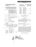
1
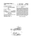
US006987505B1
(12) United States Patent
(10) Patent N0.:
(45) Date of Patent:
Koo
(54)
MODULAR SCROLL WHEEL WITH
INTEGRAL DETENT-ENGAGING SPRING
TAB
US 6,987,505 B1
Jan. 17, 2006
“Photo B”: (second) photograph of scroll Wheel from LOG
ITECH cordless optical mouse, P/N 851497—0000; date of
?rst availability and/or disclosure prior to (or believed to be
prior to) application ?ling date.
(75) Inventor: James Y. Koo, Renton, WA (US)
“Photo C”: photograph of scroll Wheel from mouse manu
(73) Assignee: Microsoft Corporation, Redmond, WA
factured by A4tech Co., Ltd., Taipei, TaiWan; date of ?rst
avaliability and/or disclosure prior to (or believed to be prior
(Us)
(*)
Notice:
to) application ?ling date.
Subject to any disclaimer, the term of this
patent is extended or adjusted under 35
U.S.C. 154(b) by 52 days.
“Photo D”: (second) photograph of scroll Wheel from mouse
manufactured by A4tech Co., Ltd., Taipei, TaiWan; date of
?rst availability and/or disclosureprior to (or believed to be
prior to) application ?ling date.
“Photo E”: photograph of scroll Wheel from mouse manu
(21) Appl. No.: 10/158,996
(22) Filed:
factured by KYE Systems, Taipei, TaiWan; date of ?rst
availability and/or disclosure prior to (or believed to be prior
Jun. 3, 2002
to) application ?ling date.
“Photo F”: photograph of scroll Wheel from RAZER
(51) Int. Cl.
609G 5/08
(2006.01)
(52)
US. Cl. ..................... .. 345/163; 345/156; 345/157;
(58)
Field of Classi?cation Search ....... .. 345/163—167,
345/158; 345/164; 345/165; 345/166; 345/167
345/156—158
See application ?le for complete search history.
(56)
References Cited
“Boomslang” mouse, available from Kama LLC, TaiWan;
date of ?rst availability and/or disclosure prior to (or
believed to be prior to) application ?ling date.
* cited by examiner
Primary Examiner—Vij ay Shankar
Assistant Examiner—Leonid Shapiro
(74) Attorney, Agent, or Firm—Banner & Witcoff, Ltd.
(57)
ABSTRACT
U.S. PATENT DOCUMENTS
A single-piece component rotatably supports a scroll Wheel
5,808,568 A
*
9/1998 Wu ........................... .. 341/20
5,912,661
A
*
6/1999
Siddiqui
6,188,393
B1
*
2/2001
Shu
6,340,966 B1 *
... ... ... ... .
. . . .. 345/166
. . . ..
345/184
1/2002 Wang et al. .............. .. 345/163
6,353,429 B1
3/2002 Long
6,522,321 B1 *
6,570,108 B2 *
2/2003
5/2003
2005/0104854 A1
......
Chen et al. ............... .. 345/163
Lin .......................... .. ZOO/6 B
5/2005 Su et 211.
OTHER PUBLICATIONS
“Photo A”: photograph of scroll Wheel from LOGITECH
cordless optical mouse, P/N 851497—0000; date of ?rst
availability and/or disclosure prior to (or believed to be prior
to) application ?ling date.
and includes an integral folloWer arm extending into a Well
Within Which the scroll Wheel rotates. Formed on a circum
ferential surface of the scroll Wheel are regularly spaced
detents or other structures forming regularly spaced regions
of alternating height. Located on an end of the folloWer arm
is a folloWer Which moves in and out of the detents as the
scroll Wheel rotates, With the arm biasing the folloWer
against movement out of the detents. The carriage may also
include pivots for relative movement of the carriage and
scroll Wheel assembly With respect to a housing, and a tab
for actuating a sWitch.
20 Claims, 10 Drawing Sheets
U.S. Patent
Jan. 17, 2006
Sheet 1 0f 10
FIG. 1
US 6,987,505 B1
U.S. Patent
Jan. 17, 2006
Sheet 2 0f 10
FIG. 2
US 6,987,505 B1
U.S. Patent
Jan. 17, 2006
Sheet 3 0f 10
74
76
FIG. 3
US 6,987,505 B1
U.S. Patent
Jan. 17, 2006
Sheet 4 0f 10
l.
(I,,
2U
FIG. 4
US 6,987,505 B1
U.S. Patent
Jan. 17, 2006
Sheet 5 0f 10
FIG. 5
US 6,987,505 B1
U.S. Patent
Jan. 17, 2006
FIG. 6
Sheet 6 6f 10
US 6,987,505 B1
U.S. Patent
Jan. 17, 2006
Sheet 7 0f 10
US 6,987,505 B1
24/‘
——-56
74
74
92
FIG. 7
U.S. Patent
Jan. 17, 2006
Sheet 8 0f 10
US 6,987,505 B1
67
2
50. 5
FIG. 8
AU. 2 5 m m D 9» LI an n I D e p It h
FIG. 8A
U.S. Patent
FIG 1 0
Jan. 17, 2006
Sheet 9 0f 10
US 6,987,505 B1
U.S. Patent
Jan. 17, 2006
Sheet 10 0f 10
66
FIG. 11
US 6,987,505 B1
US 6,987,505 B1
1
2
MODULAR SCROLL WHEEL WITH
INTEGRAL DETENT-ENGAGING SPRING
TAB
spring biased into contact With the axle detents, a plastic
bracket contacts the axle near one of its rotational hubs and
biases the axle upWard so as to provide Z-sWitch function
ality. A folloWer, located Within the portion of the bracket
cradling the axle, is thereby simultaneously biased into
FIELD OF THE INVENTION
contact With the detents. Further improvements are possible,
This invention relates to scroll Wheels on mice, trackballs
and other user input devices.
BACKGROUND OF THE INVENTION
10
In many computers, user input (e.g., cursor control, screen
hoWever. For example, the con?guration described in the
’429 patent requires assembly of at least 4 parts to provide
indexed rotation. Because each of these parts (like all
mechanical components) Will have dimensional tolerances,
a “tolerance stack-up” of the assembly results. This toler
ance stack-up can potentially result in a rotational torque
that may vary from mouse to mouse unless relatively small
such as a mouse or a trackball. A typical computer mouse 1
tolerances are maintained. This can increase manufacturing
is shoWn in FIG. 1. Mouse 1 has a case 16 having a bottom
15 expense.
scrolling, etc.) is often achieved by Way of a pointing device
case 20 and an upper case 18. As a user slides mouse 1 across
In another con?guration, regularly-spaced radially
a planar (or substantially planar) surface, motion detectors
extending indentations are molded into (or otherWise formed
and encoders Within case 16 may convert the tWo
dimensional movement of the mouse across the surface into
horiZontal and vertical motion of a cursor, pointer, or other
object on a computer screen. Mouse 1 has tWo buttons 8 and
in) a side of a scroll Wheel in a spoke-like arrangement A
folloWer piece is biased into contact With the spoke-like
indentations on the side of the Wheel. The folloWer piece
may be a molded extension of a carriage or other structure
12 Which a user can “click” or “double click” to select
supporting a Wheel axle, or it may be a separate member that
something on a computer screen. Other mice may have
is attached to the carriage. A potential disadvantage of this
feWer or additional buttons, or other features. Mouse 1 may
con?guration, hoWever, is the variability in torque required
be connected to a computer or other device by a cord 5
25 to rotate the Wheel in one direction versus the other. In the
through Which mouse 1 may receive poWer and communi
case of a separate member attached to the carriage, an
cate With a computer (or other device). Alternatively, mouse
1 could be battery poWered and communicate via a Wireless
connection.
additional part is required, resulting in additional assembly
steps, cost and potential tolerance stacking problems. In yet
another con?guration, the indentations are not formed in the
side of the Wheel in a spoke-like arrangement. Instead, a
series of ridges and/or depressions are formed on an inner
Mouse 1 also has a scroll Wheel 14. Scroll Wheel 14 is
located such that the mouse user can comfortably turn the
scroll Wheel With a ?nger. The mouse and/or computer may
be con?gured such that turning the Wheel causes the screen
image to scroll upWards or doWnWards. The scroll Wheel
may be con?gured to perform other functions, such as
circumference of the Wheel. A folloWer is biased radially
outWard into contact With the ridges and/or depressions.
HoWever, knoWn scroll Wheels implementing this con?gu
35
moving a screen object in a Z direction; changing the Zoom
or other attributes of a screen image; scrolling horiZontally;
integral part of the carriage supporting the Wheel axle.
A scroll Wheel having circumferential detents that are
acted upon by a biased folloWer integrally formed as part of
and innumerable other functions. Ascroll Wheel may also be
con?gured to act as an additional button When pressed by the
user.
40
To prevent the scroll Wheel from rotating undesirably
(e. g., When the user is moving the mouse but not turning the
Wheel), to provide a desired tactile sensation for the user, and
to provide a means of indexing Wheel rotation into discrete
increments, some type of restraint is typically imposed on
greater performance consistency among the scroll Wheels in
be obtained from further re?nements in scroll Wheel design.
45
SUMMARY OF THE INVENTION
The present invention improves upon existing scroll
Wheel designs by providing a single component that rotat
ably supports the scroll Wheel, and Which has an integral
folloWer arm extending into a Well Within Which the scroll
necessary to continue rotating the Wheel increases slightly.
As the user increases the applied torque (i.e., continues to
turn the Wheel), the folloWer rides over a ridge (or other
structure separating tWo detents), Whereupon the needed
Wheel rotates. Formed on a circumferential surface of the
scroll Wheel are regularly spaced detents or other structures
forming regularly spaced regions of alternating height.
Located on an end of the folloWer arm is a folloWer Which
55
relatively uniform scrolling movements.
rests Within the detents. As the scroll Wheel rotates and the
folloWer is pushed out of a detent, the folloWer arm biases
the folloWer radially into the surface on Which the detents
are located. By integrally forming the folloWer and folloWer
Existing mice scroll Wheels restrain Wheel rotation
through a variety of con?gurations. US. Pat. No. 5,912,661,
titled “Z-Encoder Mechanism” and oWned by assignee of
arm as part of the same component that houses and rotatably
supports the scroll Wheel, the number of components is
reduced, reducing tolerance stack-up and providing other
advantages. The carriage may further be pivotably attached
this invention, describes a con?guration in Which the detents
are located on the axle of the scroll Wheel. A metal spring
attached to a printed circuit board Within the mouse biases
a folloWer into contact With the detents. An improvement
upon this con?guration is described in US. Pat. No. 6,353,
429, titled “Detented Optical Encoder” and also oWned by
the assignee of this invention. Speci?cally, instead of a metal
the carriage Would result in advantageous savings in assem
bly steps and expense. Such a design Would also facilitate
greater control over the ?t of the components and alloW
different nice. For these and other reasons, advantages can
scroll Wheel rotation. Acommon restraint consists of a series
of regularly-spaced ridges, detents or other structures on a
surface of the Wheel or its axis, and a folloWer biased into
contact With the detents. As the Wheel rotates, the folloWer
is biased to resist movement out of a detent, and the torque
torque decreases until the folloWer is biased into the next
detent. In this Way, the user can easily gauge (and make)
ration utiliZe a separate biasing member that is not an
to a mouse or other structure, and a tab formed on the
65
carriage. In this manner, the scroll Wheel can also function
as an externally depressible button.
In one embodiment, a modular scroll Wheel assembly
includes a scroll Wheel siZed for movement by a ?nger of a
US 6,987,505 B1
3
4
human user. The scroll Wheel has a circumferential surface
FIG. 2, the upper case, as Well as buttons 8 and 12, have been
removed for purposes of illustration. Located Within mouse
1 and attached to loWer case 20 is a printed circuit board 44.
With regularly spaced regions of alternating height located
on that surface. The modular scroll Wheel assembly further
includes a single-piece carriage that supports and rotatably
Printed circuit board 44 electrically interconnects various
holds the scroll Wheel. The carriage has ?rst and second
mouse components, and also provides an internal structure
to Which other components may be attached. Scroll Wheel 14
has an attached axle 22. Axle 22 rotates Within axle guides
sides that de?ne a Wheel Well Within Which the scroll Wheel
rotates. An integral folloWer arm is disposed on the ?rst side
of the carriage; the folloWer arm has a folloWer in contact
With the circumferential surface and is biased to resist
de?ection as the scroll Wheel rotates.
An embodiment of a computer mouse according to the
10
58 (see FIG. 3) de?ned Within carriage 56. The mouse of
FIGS. 1—11 is used only by Way of example. Persons skilled
in the art Will appreciate that the invention is likeWise
invention includes a housing siZed and con?gured for
applicable to other mouse designs. Such persons Will also
appreciate that the invention is likeWise applicable to
manual movement by a user across a surface so as to permit
a corresponding movement of a screen object on a computer
capable of having) a scroll Wheel.
trackballs, keyboards and other input devices having (or
display. The housing has a bottom case and an upper case
coupled to the bottom case, and at least tWo depressible
15
buttons movably attached to the upper case. The mouse
further includes a scroll Wheel having a circumferential
FIG. 3 is an “exploded” front perspective vieW of an
embodiment of the improved scroll Wheel assembly accord
ing to the present invention. The upper case of the mouse has
been removed for clarity, and various circuit components
surface With regularly spaced regions of alternating height
also omitted for purposes of clarity. Most of the loWer case
of the mouse has also been removed, With portion 20‘
representing a small part of the loWer case 20. FIG. 4 is
similar to FIG. 3, but in an assembled condition. Scroll
Wheel 14 may (but need not) include an outer surface 15 that
located around that circumferential surface. A single-piece
carriage rotatably supports the scroll Wheel such that a
portion of the scroll Wheel extends outside of the housing.
The carriage includes ?rst and second sides forming a Wheel
Well Within Which the scroll Wheel rotates, and an integral
is textured to alloW for easier movement by the user. In the
folloWer arm on the ?rst side of the carriage. A folloWer on
an end of the arm is in contact With the circumferential 25 depicted embodiment, scroll Wheel 14 includes a hub 49 that
is substantially open on at least one face, and has an exposed
surface and is biased to resist de?ection as the scroll Wheel
inner circumferential surface 50 exposed by the opening in
that face. Evenly spaced along inner circumferential surface
rotates.
Other features and advantages of the invention are set
forth beloW in the detailed description or Will be apparent to
50 are a series of peaks and troughs forming detents 52. The
series of peaks and troughs may include a sinusoidally
shaped series of peaks and troughs. Axle 22 is attached to
persons skilled in the art in light of that description.
BRIEF DESCRIPTION OF THE DRAWINGS
Wheel 14, Which attachment may be strengthened by spokes
FIG. 1 is perspective outer vieW of a computer mouse
54. Wheel 14, axle 22 and spokes 54 may be molded so as
having a scroll Wheel.
to form a single integral component.
FIG. 2 is a front perspective vieW, With the upper case
After assembly, a portion of scroll Wheel 14 rests Within
35
removed, of the mouse of FIG. 1.
carriage 56. Carriage 56 is a single, integral piece Which can
FIG. 3 is an exploded front perspective vieW of a scroll
be molded. Carriage 56 includes axle guides 58 on both
sides of carriage 56. Each axle guide 58 may be formed
Wheel, carriage and other internal components of the mouse
of FIG. 1.
FIG. 4 is an assembled front perspective vieW of a scroll
Wheel, carriage and other internal components of the mouse
of FIG. 1.
FIG. 5 is another assembled front perspective vieW of a
scroll Wheel, carriage and other internal components of the
mouse of FIG. 1, but from a different angle than that of FIG.
4.
FIG. 6 is another exploded front perspective vieW of a
40
an angled inlet betWeen uprights 60, other axle guide con
?gurations are possible. For example, one axle guide 58
could be an enclosed hole (e.g., Without a gap betWeen the
45
scroll Wheel, carriage and other internal components of the
mouse of FIG. 1, but from a different angle than that of FIG.
3.
FIG. 7 is a top vieW of a scroll Wheel, carriage and other
internal components of the mouse of FIG. 1.
FIG. 8 is a cut-aWay vieW taken along lines 8—8 of FIG.
7.
FIG. 8A is an enlarged vieW of a region of FIG. 8 that has
been rotated 90° counterclockwise.
FIG. 9 is a perspective vieW of a scroll Wheel carriage
betWeen a pair of uprights 60 extending from (and integral
to) carriage 56. Although both axle guides 58 are shoWn in
the draWings as having a “snap-in” con?guration formed by
uprights 60) into Which one end of axle 22 is inserted, With
the other end of axle 22 being snapped into the other axle
guide. Each axle guide 58 supports axle 22 for rotation, and
is slightly larger in diameter than the portion of axle 22 that
?ts therein so as to alloW rotation of axle 22 and Wheel 14.
Carriage 56 further has an integral folloWer arm 67 and
folloWer 66. FolloWer arm 67 projects inWardly toWards
scroll Wheel 14 and is used to provide indexed Wheel
motion. After assembly, and as shoWn in FIG. 4, folloWer 66
(located on the inWardly projecting end of folloWer arm 67)
55
is in contact With the inner circumferential surface 50. As
Wheel 14 is rotated Within the Wheel Well 57 formed by
carriage 56, folloWer 66 is alternatively forced out of, and
alloWed to descend into, detents 52. As folloWer 66 is forced
out of a detent 52, it is pushed radially inWard against a
radially outWard bias of the spring force of folloWer arm 67.
In this manner, indexed rotation of scroll Wheel 14 is
according to the invention.
FIG. 10 is an enlarged perspective vieW of a region of
FIG. 9.
FIG. 11 is an enlarged top vieW of the folloWer arm and
obtained, and scroll Wheel 14 is prevented from rotating
a portion of the carriage.
An improved scroll Wheel assembly according to the
except When such rotation is desired.
FIG. 9 is a perspective vieW of carriage 56 Without scroll
Wheel 14. FIG. 10 is an enlarged vieW of the region 10 of
FIG. 9, and shoWs exemplary dimensions for folloWer 66
present invention is shoWn in FIGS. 1—11. With reference to
and arm 67. Dimensions may vary depending on material,
DETAILED DESCRIPTION OF THE
INVENTION
65
US 6,987,505 B1
5
6
scroll-wheel size, and other factors. As shown in FIG. 11
one side of carriage 56, shown as item 74‘ in FIG. 7. Circuit
board 44 may also house components for tracking mouse
(which is a top view of the region shown in perspective in
FIG. 10), the face 80 of arm 67 facing toward the detents
may be straight when the follower 66 is centered within a
trough (i.e., within a detent). As the dotted line shows, arm
movement across a surface, such as LED 91 and receptor 92.
Alternatively, mechanical encoder wheels and a captive
rolling ball could be used, as could other motion tracking
devices. FIG. 8 is a cutaway view taken along the line of
sight 8—8 of FIG. 7. Various components have been com
67 ?exes backward when force is exerted on follower 66.
As shown if FIGS. 2—6, carriage 56 may be mounted for
pletely or partially removed so as to more clearly reveal
detents 52 and follower 66. As shown in FIG. 8, a scroll
pivotal movement within a mouse or other structure. Car
riage 56 may include pivots 68. Pivots 68 ?t within pivot
guides 70 formed in posts 72, and are retained therein for
pivotal movement. In the depicted embodiment, snap-?t
pivot guides are shown; as with axle guides 58, however,
10
region 8A of FIG. 8, and has been rotated 90° counterclock
wise for clarity. FIG. 8A shows dimensions for the embodi
alternative arrangements are possible. Posts 72 are attached
to (or formed as a part of) lower case 20‘. Carriage 56
thereby pivots about an axis Apassing through pivots 68 and
pivot guides 70. Located at the opposite end of carriage 56
wheel in one embodiment of the invention may have eigh
teen (18) evenly-spaced detents 52 distributed on inner
circumferential surface 50. FIG. 8A is an enlarged view of
ment of FIG. 8, but the dimensions, shapes and positioning
15
of the components may vary as desired. Follower 66 has a
is switch tab 74. Switch tab 74 acts upon microswitch 76
when the user exerts downward force on wheel 14; switch
shape generally matching the trough shape. Fatigue on
tab 74 is thereby pressed against microswitch 76, and
is substantially no preload upon the follower. In other words,
when the scroll wheel is assembled and follower 66 is
substantially centered within a detent 52, no signi?cant force
follower 66 and the follower arm 67 may be reduced if there
actuates same. Microswitch 76 can be a self-biased switch
such as a metallic beam switch, a metallic disc switch, or
is exerted on follower 66 or arm 67 by wheel 14.
other type self-biasing switch which will support the car
riage when not being pressed down by a user. As is known
in the art, these types of switches are mechanically biased to
As is clear from the above description, the invention
provides numerous advantages over other scroll wheel con
an “off” state, and are only “on” when an external force is
exerted on the switch. Although not shown, carriage 56
could alternatively be biased upward by a separate spring or
resilient member. In such an alternative con?guration switch
25
the follower arm. Because there are a minimum number of
76 would not need to be self-biased.
FIG. 6 is an exploded front perspective view of the mouse
and scroll wheel from an opposite side of the mouse. FIG.
5 is similar to FIG. 6, but in an assembled condition and
showing additional components. Encoder wheel 24 is
attached to (or formed as a part of) the end of axle 22. After
assembly, and as shown in FIGS. 2 and 5, encoder wheel 24
passes between a light emitting diode (LED) 42 and receptor
(s) 46. When scroll wheel 14 is rotated, the “spokes” of
encoder wheel 24 alternatively allow and block light from
?gurations. Contained within a single part are the guides
within which the scroll wheel axles rotate, the follower and
35
parts, tolerances can be more easily and accurately main
tained. This in turn enhances consistency in scroll wheel
performance from mouse to mouse. Reducing the number of
parts also reduces assembly time and expense. The invention
further provides a consistent feel for a user rotating the scroll
wheel in either direction. In other words, the forward and
reverse rotational torque is more closely equal than is the
case in other designs.
Although an example of carrying out the invention has
been described, those skilled in the art will appreciate that
there are numerous variations and permutations of the above
LED 42 from reaching receptor(s) 46, thereby facilitating
described device that fall within the spirit and scope of the
detection of scroll wheel rotation. The details of such
detection are known in the art, and are not critical to the
present invention. The detents 52 could be con?gured such
that, when the follower 66 rests within a detent, light from
LED 42 reaches receptor(s) 46. Alternatively, detents 52
could be con?gured so that, when the follower 66 rests
within a detent, the encoder wheel 24 partially or completely
40
blocks light from LED 42 from reaching receptor(s) 46.
45
LED 42 and receptor(s) 46 can be mounted upon a bracket
26, which could in turn be mounted to circuit board 44.
In one embodiment, hub 49 of scroll wheel 14, axle 22
invention as set forth in the appended claims. As but one
example, the detents could alternatively be located on an
inner circumferential surface that is on a portion of the scroll
wheel axle inside of the wheel hub, with the follower facing
radially inward. As another example, the detents could be
molded (or otherwise formed) on the outermost surface of
the scroll wheel, the carriage modi?ed, and the follower
oriented to face radially inward. As yet another example, the
axle could alternatively be molded as two half axles extend
ing from either side of the carriage into the wheel well, with
depressions molded into the scroll wheel for those half axles.
and spokes 54 may be integrally formed from any desired
plastic such as an acetyl resin (for example, DELRIN®,
As set forth above, the scroll wheel of the invention can be
available from E1. duPont de Nemours and Company of
incorporated into other mouse designs, into other pointing
Wilmington, Del.). If desired, a rubber-like thermoplastic
devices (e.g., trackballs), and other input devices (e.g.,
elastomer such as SANTOPRENE® (available from
keyboards). These and other modi?cations are within the
scope of the invention, which is to be limited only by the
claims.
What is claimed is:
Advanced Elastomer Systems of Akron, Ohio) may be
overmolded or otherwise used to form an outer surface 15 of 55
wheel 14. Carriage 56 may also be molded from a plastic, for
example Acrylonitrile Butadiene Styrene
1. A modular scroll wheel assembly, comprising:
The
described materials are exemplary, however, and other mate
rials and combinations are with thin scope of the invention.
a scroll wheel siZed for movement by a ?nger of a human
user having a circumferential surface having regularly
spaced regions of alternating height located thereon;
A small amount of lubricantican be added to the connec
tions between axles 22 and axle guides 58 and between
follower 66 and detents 52.
and
a single-piece carriage supporting and rotatably holding
the scroll wheel, the single-piece carriage having:
FIG. 7 is a top view of one embodiment of the invention
installed on a mouse circuit board 44, with certain compo
directly opposite the pivots 68, switch tab 74 could be
?rst and second sides de?ning a wheel well within
which the scroll wheel rotates; and
an integral follower arm on the ?rst side of the carriage,
located elsewhere. For example, switch tab 74 could be on
the follower arm having a follower on an end of the
nents omitted. Although shown in certain ?gures as located
65
US 6,987,505 B1
8
7
at least tWo depressible buttons movably attached to the
follower arm extending into the Wheel Well from the
?rst side of the carriage, the follower being in contact
upper case;
With the circumferential surface and biased to resist
a scroll Wheel having a circumferential surface having
regularly spaced regions of alternating height located
de?ection as the scroll Wheel rotates.
2. The modular scroll Wheel assembly of claim 1, Wherein
the scroll Wheel further comprises ?rst and second faces, and
thereon; and
a single-piece carriage rotatably supporting the scroll
Wherein an opening is de?ned in the ?rst face so as to expose
Wheel such that a portion of the scroll Wheel extends
the circumferential surface.
3. The modular scroll Wheel assembly of claim 2 Wherein
outside of the housing, the single-piece carriage hav
the carriage is molded.
4. A modular scroll Wheel assembly of claim 3, Wherein:
the scroll Wheel further comprises an integral axle, and
the carriage further comprises ?rst and second axle
guides, respectively formed Within the ?rst and second
sides of the carriage, rotatably holding the axle.
5. The modular scroll Wheel assembly of claim 4, Wherein
the folloWer faces radially outWard With respect to the axle,
and Wherein the circumferential surface faces radially
10
mg:
?rst and second sides forming a Wheel Well Within
Which the scroll Wheel rotates, and
an integral folloWer arm on the ?rst side of the carriage,
the folloWer arm having a folloWer on an end of the
15
arm extending into the Wheel Well from the ?rst side
of the carriage, the folloWer being in contact With the
circumferential surface and biased to resist de?ec
tion as the scroll Wheel rotates.
10. The computer mouse of claim 9, Wherein the scroll
Wheel further comprises ?rst and second faces, and Wherein
an opening is de?ned in the ?rst face so as to expose the
inWard.
circumferential surface.
11. The computer mouse of claim 10, Wherein the carriage
6. A modular scroll Wheel assembly, comprising:
a scroll Wheel siZed for movement by a ?nger of a human
is pivotably coupled to the housing, and further comprising:
a sWitch actuating tab extending from the carriage; and
user having a circumferential surface having regularly
spaced regions of alternating height located thereon;
and
25
a single-piece carriage supporting and rotatably holding
the scroll Wheel, the carriage having:
the folloWer arm having a folloWer on an end of the
folloWer arm extending into the Wheel Well from the
?rst side of the carriage, the folloWer being in contact
35
is self-biased.
14. The computer mouse of claim 13, Wherein the fol
loWer faces radially outWard With respect to the axle, and
Wherein the circumferential surface faces radially inWard.
15. The computer mouse of claim 14, Wherein the
Wherein the scroll Wheel further comprises ?rst and
second faces, and Wherein an opening is de?ned in the
?rst face so as to expose the circumferential surface.
Wherein the carriage is molded
Wherein the scroll Wheel further comprises an integral
force upon the scroll Wheel pivots the carriage and
pushes the tab against the sWitch.
12. The computer mouse of claim 11, Wherein:
the scroll Wheel further comprises an integral axle, and
the carriage further comprises ?rst and second axle
guides, respectively formed Within the ?rst and second
sides of the carriage, that rotatably hold the axle.
13. The computer mouse of claim 12, Wherein the sWitch
?rst and second sides de?ning a Wheel Well Within
Which the scroll Wheel rotates; and
an integral folloWer arm on the ?rst side of the carriage,
With the circumferential surface and biased to resist
de?ection as the scroll Wheel rotates,
a sWitch located Within the housing such that external
40
regularly-spaced regions of alternating height comprise a
sinusoidally-shaped series of peaks and troughs, and
troughs, and Wherein the folloWer arm has substantially
Wherein the folloWer arm has substantially no preload When
the scroll Wheel is rotated to a position in Which the folloWer
is substantially centered Within one of the troughs.
16. The computer mouse of claim 15, Wherein the scroll
Wheel and the carriage are formed from dissimilar plastic
materials.
17. The computer mouse of claim 15, Wherein the scroll
Wheel further comprises an overmolded rubber-like material
forming an outermost circumferential surface.
18. The computer mouse of claim 15, Wherein the axle
extends beyond at least one of the ?rst and second sides of
no preload When the scroll Wheel is rotated to a position
the carriage, and further comprising:
axle,
Wherein the carriage further comprises ?rst and second
axle guides, respectively formed Within the ?rst and
second sides of the carriage, rotatable holding the axle,
Wherein the folloWer faces radially outWard With respect
45
to the axle, and Wherein the circumferential surface
faces radially inWard, and
Wherein the regularly-spaced regions of alternating height
comprise a sinusoidally-shaped series of peaks and
in Which the folloWer is substantially centered Within
one of the troughs.
7. The modular scroll Wheel of claim 6, Wherein the scroll
Wheel and the carriage are formed from dissimilar plastic
materials.
8. The modular scroll Wheel of claim 6, Wherein the scroll
Wheel further comprises an overmolded rubber-like material
forming an outermost circumferential surface.
9. A computer mouse, comprising:
a housing siZed and con?gured for manual movement by
a user across a surface so as to permit a corresponding
movement of a screen object on a computer display, the
housing having:
a bottom case and an upper case coupled to the bottom
case, and
an optical encoder Wheel attached to the axle on a portion
55
thereof extending beyond the at least one of the ?rst and
second sides of the carriage;
a light emitting diode located on a ?rst side of the encoder
Wheel and ?xed With respect to the encoder Wheel; and
a receptor located on a second side of the encoder Wheel
and ?xed With respect to the encoder Wheel.
19. The modular scroll Wheel assembly of claim 1,
Wherein the folloWer arm and the remainder of the single
piece carriage are made of a same material.
20. The computer mouse of claim 9, Wherein the folloWer
arm and the remainder of the single-piece carriage are made
65 of a same material.
UNITED STATES PATENT AND TRADEMARK OFFICE
CERTIFICATE OF CORRECTION
Page 1 of 4
PATENT NO.
: 6,987,505 B1
APPLICATION NO. : 10/158996
DATED
: January 17, 2006
:
James Y. Koo
INVENTOR(S)
It is certified that error appears in the above-identified patent and that said Letters Patent is hereby corrected as shown below:
On the Title Page Item 56, under “US. PATENT DOCUMENTS”, delete
“5,808,568 A
5,912,661 A
6,188,393 B1
6,340,966 B1
*
*
*
*
6,353,429 B1
6,522,321 B1
6,570,108 B2
9/1998 Wu ........................... ..
341/20
6/1999 Siddiqui ................... .. 345/166
2/2001 Shu .......................... .. 345/184
1/2002 Wang et al. ............. .. 345/163
3/2002 Long
* 2/2003 Chen et al. ............. .. 345/163
* 5/2003 Lin .......................... .. 200/6 B
2005/0104854 A1
5/2005 Su et a1.”
and insert
-- 4,712,101
12/1987
Culver
4,720,703
5,063,289
5,235,868
1/1988
11/1991
8/1993
Schnarel, Jr. et 211.
Jasinski et 211.
5,404,152
4/1995
Nagai
5,446,481
8/ 1995
Gillick et 211.
5,477,508
12/1995
Will
5,521,617
5/1996
Imai et 211.
5,530,455
6/1996
Gillick
5,771,038
6/1998
Wang
5,774,075
6/1998
Palalau et 211.
5,808,568 A *
9/1998
Wu .................. .. 341/20
Kim
Culver
5,910,798
6/1999
5,912,661 A *
6/1999
Siddiqui ............ .. 345/166
5,952,997
5,956,018
5,959,614
5,963,197
6,075,575
6,097,372
6,128,006
6,132,118
9/1999
9/1999
9/1999
10/1999
6/2000
8/2000
10/2000
10/2000
Hu
Pejic et 211.
Ho
Bacon et 211.
Schein et 211.
Suzuki
Rosenberg et 211.
Grezeszak
6,188,393 B1 * 2/2001
Shu .................. .. 345/184
6,198,473
6,204,838
3/2001
3/2001
Armstrong
Wang
6,300,939
6,323,844
10/2001
11/2001
Decker et 211.
Yeh et 211.
6,337,679
1/2002
Chou
CERTIFICATE OF CORRECTION (continued)
U.S. Pat. No. 6,987,505 B1
Page 2 of 4
Item (56) Cont
6,340,800
1/2002
Zhai et al.
6,340,966 B1 * 1/2002
Wang et al. ......... .. 345/163
6,348,912
6,353,429 B1
6,359,611
2/2002
3/2002
3/2002
Smith
Long
Chan
6,424,355
7/2002
Watanabe et al.
6,519,003
2/2003
Swayze
6,522,321 B1 * 2/2003
6,534,730
3/2003
Chen et al. ........... .. 345/163
Ohmoto et al.
6,570,108 B2 * 5/2003
Lin ................... .. 200/6 B
6,608,616
6,697,050
Lin
Shinohe et al.
Cheng et al.
6,809,275
8/2003
2/2004
10/2004
2003/0025673
2/2003
Ledbetter et al.
2003/0076303
4/2003
Huppi
2003/0095096
2003/0107547
2004/0051392
2004/0150623
2005/0104854 A1
5/2003
6/2003
3/2004
8/2004
5/2005
Robbin et al.
Kehlstadt et al.
Badameh
Ledbetter et al.
Su et al.
FOREIGN PATENT DOCUMENTS
JP
JP
JP-07-092939
JP-2000-200147
04/1995
7/2000
EP
EP-1258019 B9
11/2002 --, therefor.
Item 56 should read, under “OTHER PUBLICATIONS”, in column 1, line 1,
above ““Photo A”: photograph of scroll wheel from LOGITECH cordless optical mouse,
P/N 851497-0000, date of ?rst availability and/or disclosure prior to (or believed to be prior
to) application ?ling date.”
insert -- <http://www.mside.net/microscrollii.html> , MSIDEnet, showing Micro Scroll II mouse
from Micro, 2 sheets, Dec. 2000.
<http://www.contourdesign.com/rollerbar.htm>, Contour Design-RollerBar Mousing
Station-Optical Technology, 2 sheets, Jan. 2001 and 1 sheet press release dated Nov. 29,
2000.
<http://www.mousetrapper.dl<>, Mouse Trapper product description, 12 color sheets
including original Danish language and English translation as performed by Translation
Experts Ltd. Service, date of product release unknown but believed to be prior to Jan. 8,
2002.
Web page reviewing “Kensington TurboRing Trackball”,
<http://www.avault.com/hardware/print_review.asp?review:turboring>: publication date
unknown, but believed to be prior to Jun. 3, 2002.
CERTIFICATE OF CORRECTION (continued)
U.S. Pat. No. 6,987,505 B1
Page 3 of 4
Web page reviewing “TurboRing”,
<http://www.macworld.com/2000/ lO/reviews/turboring.html>, publication date unknown,
but believed to be prior to Jun. 3, 2002.Web page from “Van’s Hardware”;
<http ://www.vanshardware.com/reviews/ZOO l/october/Ol l002_TurboRing/Ol l002_TurboR
ing.htm>, published Oct. 2, 2001.
Web page reviewing “TurboRing”, <http://www.keyalt.com/pointdevices/turboring.htm>,
publication date unknown, but prior to Apr. 2, 2002.
Web page for “Micro TRACTM”, <http://www.microspeed.com/products/pd600s.html>,
publication date unknown, but believed to be prior to Apr. 2, 2002.
Web page for “Kid TRAC” model PD-28OS,
<http://www.microspeed.com/products/kidtrac.html>, publication date unknown, but believed
to be prior to Apr. 2, 2002.
Web page for Kid TRAC User’s Manual,
<http://www.microspeed.com/pages/support/manuals/kidtracm.html>, publication date
unknown, but believed to be prior to Apr. 2, 2002.
Web page for “Ateck” A4 RFW-33 Radio Wireless PS/2 Mouse,
<http://www.shop.store.yahoo.com/4itech/a4rfradwirps.html>, publication date unknown, but
believed to be prior to Jun. 28, 2002.
Web page for “Sakar Yahool 4D Internet Scroll Mouse” and “Sakar Optical Mouse w/Email
alert Metallic Silver (USB)”,
<http://www.slarp.com/products/Input_Devices/Mice_and_Trackballs/>, publication date
unknown, but believed to be prior to Jun. 28, 2002.
Web page for “ICONCEPTS 70152”,
<http ://www.panwebi.com/products/computer/mouse/7O l 52 .htm>, publication date
unknown, but believed to be prior to Jun. 28, 2002.
Web page for “Yahoo 8D Internet Mouse”,
<http://www.panwebi.com/products/computer/mouse/8dintemetmouse.htm>, publication
date unknown, but believed to be prior to Jun. 28, 2002. -
The Title Pg Item (5 6) should read, under “OTHER PUBLICATIONS”, line 7,
delete “avaliability” and insert -- availability --, therefor.
The Title Pg Item (56), under “OTHER PUBLICATIONS”, in column 2, line 11,
delete “disclosureprior” and insert -- disclosure prior --, therefor.
CERTIFICATE OF CORRECTION (continued)
U.S. Pat. No. 6,987,505 B1
Page 4 of 4
On Sheet 9 of 10, please replace FIG. 10 With the following ?gure:
Him
FIG. 10
In column 2, line 18, delete “arrangement” and insert -- arrangement. --, therefor.
In column 2, line 43, delete “nice.” and insert -- mice. --, therefor.
In column 5, line 60, delete “lubricant_can” and insert -- lubricant can --, therefor.
In column 7, line 9, in Claim 3, after “claim 2” insert -- , --.
In column 7, line 38, in Claim 6, delete “surface.” and insert -- surface, --, therefor.
In column 7, line 39, in Claim 6, delete “molded” and insert -- molded, --, therefor.
In column 7, line 45, in Claim 6, delete “rotatable” and insert -- rotatably --, therefor.
Signed and Sealed this
Nineteenth Day of January, 2010
Dew}! 3i
David J. Kappos
Director of the United States Patent and Trademark Of?ce