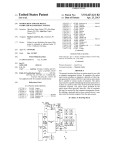
1
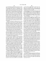
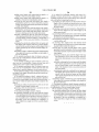
USOO8749481B2
(12) United States Patent
(10) Patent No.:
Lee et a].
(54)
(45) Date of Patent:
OPTION MENU FOR USE WITH A
5,721,842 A
COMPUTER MANAGEMENT SYSTEM
5,732,212 A
5,821,918 A
(75) Inventors: Alex Lee, Taipei Hsien (TW); Yee LiaW,
Wareen, NJ (US); Alan Hsu, Taipei
Hsien (TW)
5,884,096 A
5,913,034 A
5,937,176 A
5,978,389 A
-
_
-
-
6,112,264 A
(73) A551gnee. gingtan Americas, Inc., Somerset, NJ
6,119,148 A
6,138,191 A
( * ) Notice:
A
1 N
.
Jun. 10, 2014
2/ 1998 Beasley
3/1998 PerholtZ
10/1998 Reinert et a1.
3/1999 Beagley
61999 Malconn
8/1999 Beasley
11/1999 Chen
8/2000
Beasley
9/2000 Chen
10/2000 Fujii et al.
Subject to any disclaimer, the term of this
3:323 et 31
patent is extended or adjusted under 35
(21)
US 8,749,481 B2
6,505,245 B1
100% North et al‘
U-S~C~ 154(b)by 820 days~
6,554,709 B1 *
4/2003 Brenner etal. ............... .. 463/42
12/110 797
6,557,170 B1*
4/2003 Wilder et a1. ............... .. 725/130
0.:
pp
’
(22) Filed:
(Continued)
Apr. 28, 2008
OTHER PUBLICATIONS
(65)
Prior Publication Data
Trial Transcript, Apex v. Raritan, Southern District of New York,
US 2008/0244662 A1
(62)
(51)
Oct. 2, 2008
Case NO'01_CV_4435,V01‘1151112002,
Related US. Application Data
(Continued)
Division of application No. 10/734,602, ?led on Dec.
12, 2003, noW Pat. No. 8,427,421.
Primary Examiner i Lun_Yi Lao
Int, Cl,
Assistant Examiner * Shaheda Abdin
G09G 5/00
(52) US. Cl.
(2006.01)
USPC .......... .. 345/156; 345/157; 345/1.1; 345/204;
58
F M f Cl
( ) UISPCO
_?
_
(57)
ABSTRACT
5 3451/1589; 715/856; 715/810
Amethod for improving video quality of a video stream. The
as“ ugxg/ll leafcs 2 0 4 80 87 156 157
"""""" 5689' 7’15'/7’71 8’5 6 T81 7137201f
’
’700283 7’25/37i38’
method decodes the video stream and generates subblocks of
video data from the video stream. The method then removes
effects of subblock boundaries from previous deblocking.
See application ?le for complete search history
Each subblock is then smoothed to create pixel values and
'
(56)
optionally, subblocks are merged if a predetermined quality is
References Cited
not achieved from the smoothing analysis. The pixels values
U.S. PATENT DOCUMENTS
blocks are deblocked and then at least one subblock is out
are ?lled into each pixel position in the subblock. The sub
5,257,390 A
5,268,676 A
5,353,409 A
10/1993 Asprey
12/1993 Asprey et al.
10/1994 Asprey et al.
5,526,024 A *
6/1996 Gaglianello et a1. ........ .. 345/547
5,648,795 A
7/1997 Vouriet al.
putted to a rendering device.
10 Claims, 11 Drawing Sheets
US 8,749,481 B2
Page 2
(56)
References Cited
U.S. PATENT DOCUMENTS
Defendant Raritan Computer, Inc.’s Supplemental Response to
Plaintiffs Second Set of Interrogatories (Nos. 9-12), Dec. 12, 2001.
DEI, Central Control of Multiple PCs Without Massive Cabling,
product brochure, Nov. 1992.
6,671,756 B1
12/2003 Thomas et al.
Expert Report by Joseph C. McAlexander Regarding Infringement
6,768,501 B2
6,771,213 B2
7,310,775 B2
7/2004 Kitagawa et al.
8/2004 Durst
12/2007 Cooper et a1.
andValidity ofU.S. Patent Nos. 5,884,096, 5,937,176 and 6,112,264,
7,512,906 B1*
2003/0035006 A1
2004/0131340 A1
3/2009
Baier et al. .................. .. 715/866
2/2003 Kodosky et al.
7/ 2004 Antoun et a1.
Jan. 3, 2001.
Expert Report by Joseph C. McAlexander Regarding Infringement
andValidity ofU.S. Patent Nos. 5,884,096, 5,937,176 and 6,112,264,
Jan. 3, 2001. Claim Charts.
Expert Report of Michael H. Davis, Jan. 13, 2002.
OTHER PUBLICATIONS
Expert Report of Sharad Malik, Regarding Noninfringement and
Tron International, Inc., KVM Products Catalogs, 1997.
Tron International, Inc., Products Catalogs, 1996.
Tron International, Inc., Product Brochure, 1997, 4 pages.
Unisys, PW2 Advantage Series Rackmount Server, 1995.
Yee Liaw Deposition Transcript, Case No. 01-CV-4435, Mar. 3,
Invalidity of US. Patent Nos. 5,884,096, 5,937,176 and 6,112,264,
Jan. 13, 2002. (Unexecuted).
File History ofU.S. Patent No. 5,721,842, Feb. 24, 1998.
File History ofU.S. Patent No. 5,732,212, Mar. 24, 1998.
File History ofU.S. Patent No. 5,884,096, Mar. 16, 1999.
File History ofU.S. Patent No. 5,937,176, Aug. 10, 1999.
File History ofU.S. Patent No. 6,112,264, Aug. 29, 2000.
File History ofReissue US. Patent No. 5,732,2 12, Apr. 11, 2002. Part
2005.
Yee-Shung Liaw Deposition Transcript, Case No. 01-CV-4435, Dec.
6, 2001.
The list of docket reports in the litigation: Avocent Redmond Corp. v.
Raritan Computer, Inc., Civil Action No. 1:01-CV-04435(PKC),
United States District Court for the Southern District of New York.
Adder, Products Brochure, APX 304572-304579, Apr. 1, 1998, 8
pages.
AdderViewOSD, Products Brochure, RCI 173246-173279, Aug. 1,
2002.
Avocent’s Pre-Markman Hearing Memorandum in Support of its
Proposed Claim Constructions (Dec. 15, 2004).
Avocent Redmond’s Answering Pre-Markman Hearing Brie?ng
(Jan. 18, 2005).
1.
File History ofReissue US. Patent No. 5,732,2 12, Apr. 11, 2002. Part
2.
File History ofU.S. Appl. No. 10/032,325, Jun. 14, 2004.
Findings and Conclusions, Apex v. Raritan, Civil Action No. 01-CV
0035, Feb. 25, 2002.
Investor’s Business Daily, Box Keeps Monitors, Mice to a Minimum,
Sep. 8, 1997.
Joseph C. McAlexander Deposition Transcript, Case No. 01-CV
4435, Apr. 27, 2005.
KVM Switch History, Aug. 2, 2002, 2 pages.
KVM Switches Roundup, Windows NT Magazine, Jul. 1997.
Lan Times, The beauty of Apex is a two-sided story, Nov. 20, 1995.
Apex et al, Products Brochure, APX 316564-316621.
Apex et al, Products Brochure, APX 316848-316909.
Apex et al, Products Brochure, APX 316910-316969.
Apex, SwitchBack User Guide, 1995.
Apex’s Motion on the PolyCon Catalog and Supporting Memoran
dum, Jan. 15,2002.
Apex’s Proposed Markman Findings, Jan. 25, 2002.
Appendixl to Apex’s Proposed Markman Findings, Jan. 25, 2002.
304605, Jun. 1, 1998.
Lu, E&J Int. 4-Port KVM Switch, Jul. 4, 2001.
Marksman Transcript, Avocent v. Raritan, Civil Action No. 4435,
Feb. 3, 2005.
Marksman Transcript, Avocent v. Raritan, Civil Action No. 4435,
Feb. 4, 2005.
Badman, Switching into High Gear, Network Computing, Apr. 30,
4435, (Mar. 11,2005).
Lightwave Communications, Inc., Product Brochure, APX 304594
Memorandum and Order on Marksman issues, Case No. 01-CV
Bruce McNair Deposition Transcript, Case No. 01-CV-4435, May 5,
Network Computing, Product Brochure, May 15, 1995, 5 pages.
Network Technologies Inc., Product Brochure, 1998, 2 pages.
Network World, advisement, Jul. 6, 1992.
2005.
Ocean Isle, Reachout Product Brochure, RCI 172996-173006, Jun.
2001 .
Belkin, The OmniView Pro User Manual, Jul. 16, 2001.
Compaq, White papers, 1996, APX 083313-APX 083326, APX
1994.
083335-APX 083389.
2005.
PC World, New Products, May 1995, 2 pages.
PolyCon GmbH Data System Inc., product catalogs, APX 024328
042697, prior to Spring, 1995.
Ching-I Hsu Deposition Transcript, Case No. 01-CV-4435, Mar. 11,
Cybex, Director Installer/User Guide, Nov. 1996.
Press Release, Maintain Error-Free Central Control of 128 PCs from
Cybex, 4 x P & 1 x P KVM Switches Guide to Applications, 1996.
One Set of Keyboard, Mouse, and Monitor, Feb. 4, 1999, 1 page.
Datavision, Product Brochure, 1992, 3 pages.
Declaration of Joseph C. McAlexander in Support of Apex’s Motion
for a Preliminary Injunction, Sep. 17, 2001.
Declaration of Joseph C. McAlexander, III in the Civil Action No.
01-CV-4435, Dec. 15, 2004.
Declaration of Sharad Malik, Ph. D., Jan. 8, 2002.
Declaration of Sharad Malik, Ph.D. (Jan. 18, 2005).
Protest Under 37 CFR 1.291 Filed in US. Patent No. 08/969,723,
Feb. 13, 1999.
Defendant Raritan Computer Inc.’s Claim Construction Statement
(Dec. 15,2004).
Defendant Raritan Computer Inc.’s Motion for Partial Summary
Judgment (Jan. 8, 2002).
Defendant Raritan Computer Inc.’s Proposed Findings of Fact and
Conclusions of Law, Apr. 27, 2005.
Defendant Raritan Computer Inc.’s Reply to Avocent’s Proposed
Raritan, CompuSwitch, Mar. 16, 1998, 1 page.
Raritan, Dominion KSX, Jul. 19, 2003, RCI 139356-139371.
Raritan, Dominion KX and Dominion KSX, 2004, 181193-181211.
Raritan, MasterConsole MXU2, Jul. 31, 2001.
Raritan, MasterConsole II, User’s Manual, 2000.
Raritan, Paragon UMT2161, RCI 147483-147505, Jul. 5, 2002.
Raritan, Paragon User’s Guide, Jun. 15, 2000.
Raritan, Paragon II User Manual, 2004.
Raritan, Products Brochure, 2004-2005, p. 185899-185912.
Raritan, Product Introduction, Oct. 23, 2000.
Rebuttal Expert Report of Joseph C. McAlexander Regarding Valid
ity and Infringement of US Patent Nos. 5,884,096, 5,937,176 and
Claim Constructions (Jan. 18, 2005).
6,112,264, Apr. 11,2005.
Defendant Raritan Computer, Inc.’s Response to Plaintiffs Second
Defendant Raritan Computer, Inc.’s Second Set of Interrogatories to
Plaintiff Apex, Nov. 16, 2001.
Rextron, Product Brochure, Aug. 1, 2002, 5 pages.
Rose Electronics, “Master Switch Installation and Operation
Manual,” 1991.
Rose Electronics, UltraView Installation and Operation Manual,
Defendant Raritan Computer, Inc.’s Supplemental Response to
Plaintiffs First Set of Interrogatories (Nos. 9-12), Aug. 31, 2001.
Rose Electronics, Ultra View, Aug. 1, 2002, RCI 173332-173336.
Set of Interrogatories (Nos. 9-12), Oct. 30, 2001.
1991-1997.
US 8,749,481 B2
Page 3
(56)
References Cited
OTHER PUBLICATIONS
Startech Computer Products Ltd., Product Press Release, APX
304618-304619, Feb. 1998.
Supplemental Expert Report of Bruce McNair Regarding United
States Patent Nos. 5,884,096 & 6,112,264 and 5,937,176, Apr. 17,
2005.
Supplemental Expert Report of Joseph C. McAlexander Regarding
Infringement of US. Patent Nos. 5,884,096, 5,937,176 and
6,112,264, Mar. 22, 2005.
Supplemental Expert Report of Michael H. Davis, Apr. 18, 2005.
SwitchCom, ProServer, Aug. 1, 2002, 2 pages.
Tikkler, Belkin OmniView SE 4-Port KVM Switch, Nov. 8, 2000.
Tony Dekerf and Gary D. Davis, “A Close Look At Modern Key
board, Video & Mouse Switches,” 1995.
Trial Transcript, Apex v. Raritan, Southern District of New York,
Case No. 01-CV-4435, vol. 1, Jan. 2002.
Trial Transcript, Apex v. Raritan, Southern District of New York,
Case No. 01-CV-4435, vol. 2, Jan. 2002.
Trial Transcript, Apex v. Raritan, Southern District of New York,
Case No. 01-CV-4435, vol. 3, Jan. 2002.
Trial Transcript, Apex v. Raritan,
Case No. 01-CV-4435, vol. 4, Jan.
Trial Transcript, Apex v. Raritan,
Case No. 01-CV-4435, vol. 5, Jan.
Trial Transcript, Apex v. Raritan,
Case No. 01-CV-4435, vol. 6, Jan.
Southern District of New York,
2002.
Southern District of New York,
2002.
Southern District of New York,
2002.
Apex, OutLook User Guide, Apr. 1997.
Apex PC Solutions, Users Guide, Apr. 1993.
Apex et al, Products Brochure, APX 316564-316621, prior to 1995.
Apex et al, Products Brochure, APX 316848-316909, 1987-1998.
Apex et al, Products Brochure, APX 316910-316969, 1983-1998.
Avocent Redmond’s Supplemental Responses to Raritan’s Second
Set ofPost-Remand Interrogatories (Nos. 15R-17R), Mar. 14, 2005.
Apex, OutLook User Guide, 1997.
Apex et al., Products Brochure, APX 082949-082971, 1996.
Apex PC Solutions, Users Guide, 1993.
Apex, Products Brochure, APX 018983-018996, Jan. 7, 1997.
Apex, Products Brochure, APX 019103-019121, 1995-1996.
Apex, Products Brochure, APX 056304-056346, Oct. 1, 1998.
Apex’s Sales Brochure, Sep. 1, 1998, 1 page.
Of?ce Actions mailed on Sep. 9, 2011 and Jul. 11, 2012 in related
U.S. Appl. No. 12/110,763.
* cited by examiner
US. Patent
Jun. 10, 2014
Sheet 1 0f 11
US 8,749,481 B2
US. Patent
Jun. 10, 2014
Sheet 2 0f 11
.5: 2% mom
#55I.
9:5:
won
82, as? in
1|
:25:0 M386
F,
n
83>
E32
US 8,749,481 B2
US. Patent
Jun. 10, 2014
599
Sheet 3 0f 11
US 8,749,481 B2
(Option)
14.513 MHZ
394
--—-P
H s c
P“-
CI k
0C
J—> Buffer
—Z/n_’ E
362
—
396
-——592
390
$121:
Ir- ---------------- "-1
PM “i:
|
T a“
H.
393
5
378
1
(572
M
M:
E
:
:
E
E
1'»5_4
E
I
I
System Level IC
inc—v"
@
5W
384 582
--:
Saw
__
059 MM HEB
354
)
DVA
E
(outline)
E
(Body)
:
1
%7_-§‘£'§°rl'“189_93_0_ £C§__J
v 5)“
‘—
l
4——H|
"5
i
:
L.“22:9":=;°:_"E¢22_°§9-19§J
4—;4 MHZ
m
RGB
386
:
r——— —————————————— "q
\
H 5m
)
i
l
l
m H Syn;
:
|
_:
580
Connector
E
1&9
a
4 363
RGB
\
370
\
—
31B
553
FIG. 28
US. Patent
Jun. 10, 2014
6100
Red
Green/ H Sync 61 00
/
BSynclue/V
Fl-L_ _I4
Sheet 4 or 11
US 8,749,481 B2
US. Patent
Jun. 10, 2014
Sheet 5 0f 11
US 8,749,481 B2
W
m
MODE A: 252, 144 COLORS
MODE B: 512 COLORS
l
l
-
l
I
-
l_—.__....l
MODE C: 8 COLORS
MODE O: 8 COLORS
FIG. 3
US. Patent
Jun. 10, 2014
US 8,749,481 B2
Sheet 6 0f 11
$ng
§
3%.
MJ
mm
5.
0
CNN)p
0
o
0
=2
h
OIU+
‘
?
k
Iw
w
m
+Nu“)
Am
0mm8“
gm?m
83.52%>:5
US. Patent
Jun. 10, 2014
Sheet 7 0f 11
.52: a
»
@%
US 8,749,481 B2
QH
\ am: mm
H
.F
OI:
h,
I
:8 Eu
%
%dil mz 5823>5 Q
H
“L2B0E:8S
50:|3I2.
.OEm
US. Patent
Jun. 10, 2014
Sheet 8 0f 11
US 8,749,481 B2
U.S. Patent
Jun. 10, 2014
Sheet 9 0f 11
CO
,—
IF
Hm
olmw
lW
o:
US 8,749,481 B2
US. Patent
Jun.10,2014
an
Sheet100f11
IG
no“.
IOQ
~12.
.‘C
aIn.
mow
a
ono“
0
no“
mmw
o
a
o
a
+|l\@oh
US 8,749,481 B2
US. Patent
Jun. 10, 2014
Sheet 11 0111
US 8,749,481 B2
Connected
Connected
Connected
w
w
w
Computer
Computer
818 ‘
Computer
818‘1
w
B1B\_I
m
830 a
§.1_6
830
CPU
830 a
CPU
Q
CPU
E
N
f
I
832
E
832
_
I
f
832
V
I
d-—--—
Smtchlng Devlce
'
%
“'
Siitch
CPU
826
Video
@
Switch q
v
I
@
‘7
i
|o§| |81_v| 1.1.;
Mood
002
Cu'sor
'
'
W m,
Moe
B]!
m
FIG. 9
I
v
m
8.0.8
Client
Keybwd
m,
M
1m
we
Moe
804
US 8,749,481 B2
1
2
OPTION MENU FOR USE WITH A
COMPUTER MANAGEMENT SYSTEM
between the system administrator’s user console and remote
computer equipment is often not a feasible alternative.
Space is also an important concern for many networked
CROSS-REFERENCE TO RELATED
APPLICATIONS
computer environments, especially large-scale operations
This application is a divisional of application Ser. No.
10/734,602, ?led on Dec. 12, 2003, now US. Pat. No. 8,427,
421 issued onApr. 23, 2013, entitled “OPTION MENU FOR
USE WITH A COMPUTER MANAGEMENT SYSTEM,”
house a keyboard, video monitor, and cursor control device
such as data-centers, server-farms, web-hosting facilities, and
call-centers. These environments typically require space to
for each piece of computer equipment and for all of the wiring
required to connect and power these components. As more
equipment is added to a computer network, it becomes more
probable that the space required for the equipment and asso
ciated cabling will exceed the space allotted for the network.
which is incorporated herein by reference. This application
also relates to co-pending US. patent application Ser. No.
12/110,763, ?led on Apr. 28, 2008, now abandoned, entitled
Therefore, network architecture, equipment size, and avail
able space are important issues when designing an effective
“OPTION MENU FOR USE WITH A COMPUTER MAN
AGEMENT SYSTEM.”
FIELD OF THE INVENTION
The present invention relates generally to an option menu
for use with a computer management system. Speci?cally, the
enhanced video display of the present invention combines or
20
computer network environment.
One method of reducing the amount of space required to
house a computer network is to eliminate any equipment (i.e.,
keyboard, video monitor, cursor control device, etc.) that is
not essential for proper operation of the computer network.
Elimination of this equipment also eliminates the wiring
associated with such equipment. This equipment and its asso
ciated wiring may be eliminated if a system administrator is
organizes multiple video signals to provide a single option
able to access the remote computers from one user console,
menu video display having more colors, more characters,
and/ or a larger size than traditional option menus. Although
the present invention may be utilized in many applications, it
is described herein to create an option menu that is incorpo
rated within a computer/ server management system. That is,
the enhanced video display provides a menu of options (e. g.,
computers connected to the management system, video dis
thereby eliminating the dedicated equipment and its associ
ated wiring. Elimination of this unnecessary equipment
25
decreases the amount of space required for computer network
environments.
A keyboard, video monitor, and mouse (“KVM”) switch
ing system may be utilized to allow one or more user work
30 stations to select and control any one of a plurality of remote
play adjustment settings, diagnostics, etc.) that is displayed
computers via a central switching unit. Such systems are well
on a system user’s monitor. The system user then responds to
known in the art and have been used by system administrators
for at least 10 years. Speci?cally, a KVM switching system
the option menu (i.e., makes a selection) via the user’s key
board and/or cursor control device.
35
BACKGROUND OF THE INVENTION
In a typical computer environment, a Local Area Network
(LAN) allows for one or more computer servers to be con
nected to several computers such that the resources of each
server are available to each of the connected computers. In
this system, a dedicated keyboard, video monitor, and cursor
control device may be employed for each computer and com
40
methods known in the art. For example, the computer man
agement system component can include an array of buttons
where each button corresponds with the desired remote com
puter server.
To maintain proper operation of the LAN, the system
allows a system user to control a remote computer using a
local user workstation’ s keyboard, video monitor, and cursor
control device as if these local devices were directly con
nected to the remote computer. In this manner, a system user
may access and control a plurality of remote computers, such
as servers, from a single location (i.e., the location of the user
workstation). The system user may select a speci?c remote
computer to access or control using any one of a variety of
45
puter. Alternatively, a user can select the computer from a list
displayed on a computer management system component’s
administrator must maintain and monitor the individual serv
ers and computers. This maintenance frequently requires the
LCD or LED display, press one or more hot keys on the local
system administrator to perform numerous tasks from the
user workstation’s keyboard (e.g., F1, ALT-F1, F2, etc.),
user console located at each server or computer. For example,
to reboot a computer or to add or delete ?les, the system
administrator is often required to operate the server or com
puter from its local user console, which may be located at a
substantial distance from the system administrator’s com
puter. Therefore, to accomplish the task of system adminis
tration, the system administrator must often travel far dis
select the remote computer from a list displayed on the user
50
etc.
The following references, which are discussed below, were
found to relate to the ?eld of computer management systems:
55
tances to access the local user consoles of remotely located
servers and computers.
As an alternative, dedicated cables may be installed from
each remotely located server and computer to the system
administrator’s user console to allow the system administra
60
mitted signal often results. Thus, utilizing dedicated cables
holtz et al. US. Pat. No. 5,732,212 (“Perholtz”), Chen US.
Pat. No. 5,978,389 (“Chen ’389 patent”), Chen US. Pat. No.
6,119,148 (“Chen ’ 148 patent”), Fujii et al. US. Pat. No.
sley”), and Wilder et al. US. Pat. No. 6,557,170 (“Wilder”).
ing and wire harnessing, both of which may require
equipment increases, a decrease in the quality of the trans
Asprey US. Pat. No. 5,257,390 (“Asprey ’390 patent”),
Asprey US. Pat. No. 5,268,676 (“Asprey ’676 patent”),
Asprey US. Pat. No. 5,353,409 (“Asprey ’409 patent), Per
6,138,191 (“Fujii”), Beasley US. Pat. No. 6,345,323 (“Bea
tor to fully access and operate the remote computer equip
ment. However, such an alternative requires substantial wir
tremendous cost. Additionally, as the distance between the
system administrator’ s user console and the remote computer
workstation’ s monitor by pointing to it or scrolling to it using
the user workstation’s keyboard and/or cursor control device,
65
TheAsprey ’390 patent, ?led on Jul. 26, 1991 and issued on
Oct. 26, 1993, discloses an extended range communications
link for coupling a computer to a mouse, keyboard, and/or
video monitor located remotely from the computer. The end
of the link that is coupled to the computer has a ?rst signal
US 8,749,481 B2
3
4
conditioning network (i.e., a network of circuitry that damp
tion may be connected either via the Public Switched Tele
ens the ringing and re?ections of the video signals and biases
them to a predetermined voltage level) that conditions the
keyboard, video monitor and mouse signals. Conditioning the
phone System (“PSTN”) and modems or via direct cabling.
The Chen ’389 patent, ?led on Mar. 12, 1998 and issued on
Nov. 2, 1999, discloses a device for multiplexing the video
output of a plurality of computers to a single video monitor.
The system includes three sets of switches for receiving the
red, green, and blue components of the video signals from
each computer. To select the video output of a speci?c com
puter for display on the video monitor, a user inputs two video
video monitor signals includes reducing their amplitude in
order to minimize the “crosstalk” induced on the conductors
adjacent to the video signal conductors during transmission
of the video signals. This ?rst signal conditioning network is
coupled to an extended range cable having a plurality of
conductors that transmits the conditioned signals, power, and
selecting signals into a control signal generating circuit.
Depending upon the inputted video selecting signals, the
control signal generating circuit produces an output signal
logic ground potentials to a second signal conditioning net
work (i.e., a network of circuitry that terminates the video
signals using a voltage divider and ampli?es them), which
corresponding to the selected video output. Thereafter, a con
restores the video signals to their original amplitude and
trol signal is generated that indexes the three sets of switches
to switch the video signals being output by the desired com
puter to the single video monitor. The three sets of switches
transfer the incoming video signals to three sets of switch
circuits and current amplifying circuits that provide input and
outputs them to a video monitor.
The Asprey ’ 676 patent, ?led on Mar. 5, 1990 and issued on
Dec. 7, 1993, discloses a communications link for use
between a computer and a display unit, such as a video moni
tor, that allows these two components to be located up to three
hundred (300) feet apart. An encoder located at the computer
end of the communications link receives analog red, green,
and blue signals from the computer and inputs each signal to
a discrete current ampli?er that modulates the signal current.
output impedance matching, respectively. The tuned video
20
The Chen ’148 patent, ?led on Jul. 29, 1998 and issued on
Sep. 12, 2000, discloses a video signal distributor that
receives, processes, and distributes video signals received
Impedance matching networks then match the impedance of
the red, green and blue signals to the impedance of the cable
and transmit the signals to discrete emitter-follower transis
from one or more computers to a plurality of video monitors.
25
these signals are ampli?ed prior to inputting them to the video
monitor. Concurrently, the horizontal synchronization signal
30
matched to the impedance of the cable, thereby allowing the
conductor to attenuate the horizontal synchronization signal
and reduce noise radiation.
TheAsprey ’409 patent, ?led on Jul. 19, 1990 and issued on
Oct. 4, 1994, discloses an extended range communications
The video signal distributor includes three transistor-based,
voltage-amplifying circuits to individually amplify the red,
tors located at the video monitor end of the cable. Thereafter,
is inputted to a cable conductor and its impedance is not
signals are then displayed on the single video monitor.
green and blue video signals received from each computer
prior to transmitting these signals to a video monitor. The
video signal distributor also includes a synchronization signal
buffering device that receives horizontal and vertical syn
chronization signals from each computer and generates new
synchronization signals based upon the quantity of video
35
link for transmitting transistor-transistor logic video signals
signals that are output to the video monitors.
Fujii, ?led on Feb. 10, 1998 and issued on Oct. 24, 2000,
discloses a system for selectively operating a plurality of
computers that are connected to one common video monitor.
from a local computer to a video monitor located up to a
The Fujii system includes a data input device for entering data
thousand feet (1,000) from the computer. The link includes a
?rst signal conditioning circuit (i.e., a circuit that reduces the
amplitude of the video signals, biases them to a selected
potential, and applies them to discrete conductors of an
extended cable) located at the computer end of the link for
in any one of the plurality of connected computers. The sys
tem also includes a main control circuit, which is connected to
the data input device, and a selection circuit for providing the
40
entered data and receiving the video signals from the selected
conditioning the received signals and transmitting them via
the extended cable to a second signal conditioning circuit.
The second signal conditioning circuit (i.e., a circuit that
45
utilizes a threshold or pair of thresholds to effect reconstruc
tion of the video signals prior to applying the signals to a
video monitor) receives the transmitted video signals prior to
inputting them to the video monitor. According to the Asprey
’409 patent, performance of this process reduces the appear
ance of high frequency video noise on the keyboard clock
computer. A user selects a remote computer by supplying the
command code associated with the desired remote computer
utilizing the keyboard and/or mouse. A selection circuit
receives the inputted commands and identi?es the selected
computer. The selection circuit then sends a signal indicative
of the selected remote computer to a main control circuit,
which provides communication between the keyboard, video
50
monitor, and mouse and the selected remote computer.
Similar to Perholtz, Beasley, ?led on Jun. 9, 2000 and
issued on Feb. 5, 2002, discloses a speci?c implementation of
conductor of the transmission cable, thereby preventing key
a computerized switching system for coupling a local key
board errors.
board, mouse and/or video monitor to one of a plurality of
Perholtz, ?led on Jan. 13, 1994 and issued on Mar. 24,
1998, discloses a method and apparatus for coupling a local
user workstation, including a keyboard, mouse, and/ or video
monitor, to a remote computer. Perholtz discloses a system
remote computers. In particular, a ?rst signal conditioning
55
a list of connected remote computers on the local video moni
tor. To activate the menu, a user depresses, for example, the
“print screen” key on the local keyboard. The user selects the
desired computer from the list using the local keyboard and/or
wherein the remote computer is selected from a menu dis
played on a standard size personal computer video monitor.
Upon selection of a remote computer by the system user, the
remote computer’s video signals are transmitted to the local
60 mouse.
According to Beasley, the on-screen programming circuit
requires at least two sets of tri-state buffers, a single on-screen
processor, an internal synchronization generator, a synchro
user workstation’s video monitor. The system user may also
control the remote computer utilizing the local user worksta
tion’s keyboard and monitor. The Perholtz system is also
capable of bi-directionally transmitting mouse and keyboard
signals between the local user workstation and the remote
computer. The remote computer and the local user worksta
unit includes an on-screen programming circuit that displays
65
nization switch, a synchronizationpolarizer, and overlay con
trol logic. The ?rst set of tri-state buffers couples the red,
green, and blue components of the video signals received
from the remote computer to the video monitor. That is, when
US 8,749,481 B2
5
6
the ?rst set of tri-state buffers are energized, the red, green,
and blue video signals are passed from the remote computer
to the local video monitor through the tri-state buffers. When
the ?rst set of tri-state buffers are not active, the video signals
from the remote computer are blocked. Similarly, the second
set of tri-state buffers couples the outputs of the single on
board and mouse to select and control the power supply of the
desired remote computer. Wilder incorporates a single on
screen processor for generation of the list of remote comput
ers.
In view of the foregoing, a need clearly exists for a com
screen processor to the video monitor. When the second set of
tri-state buffers is energized, the video output of the on- screen
puter management system that is compatible with both stan
dard size video monitors (e. g., monitors ranging from 13" to
21") and larger than standard size video monitors. In addition,
programming circuit is displayed on the local video monitor.
When the second set of tri-state buffers is not active, the video
output from the on-screen programming circuit is blocked.
Alternatively, if both sets of tri-state buffers are energized, the
remote computer video signals are combined with the video
provides an option menu that contains more characters and/or
more colors than those available with a single on-screen pro
cessor. There is also a need for a computer management
a need clearly exists for a computer management system that
signals generated by the on-screen processor prior to display
system having an option menu that provides greater ?exibility
and de?nition for identifying options and connected comput
on the local video monitor.
ers. Furthermore, there is a need for a computer management
The on-screen programming circuit disclosed in Beasley
also produces its own horizontal and vertical synchronization
signals. To dictate which characters are displayed on the
of available colors, which may be used to color code con
nected computers or options for purposes such as identifying
video monitor, the CPU sends instructional data to the on
the general location of each connected computer (e.g., con
system that provides an option menu having a large quantity
screen processor. This causes the on-screen processor to 20 nected computers having a blue description are located in
retrieve characters from an internal video RAM for display on
the local video monitor.
Quadrant 1, connected computers having a green description
are located in Quadrant 2, etc.). Furthermore, there exists a
need for a computer management system that provides an
option menu that allows the system user to choose the desired
The overlaid video image produced by the on-screen pro
cessor, namely a Motorola MCl41543 on-screen processor,
is limited to the size and quantity of colors and characters that
25
are available with the single on-screen processor. In other
mode of operation (e.g., larger video display, more colors,
words, the Beasley system is designed to produce an overlaid
more characters, etc.). Also, a need exists for a computer
management system that provides an option menu that allows
video that is sized for a standard size computer monitor (i.e.,
not a wall-size or multiple monitor type video display) and is
the system user to choose the size of the video monitor that is
limited to the quantity of colors and characters provided by
connected to the local user workstation.
30
SUMMARY OF THE INVENTION
the single on-screen processor.
During operation of the Beasley system, a remote com
puter is chosen from the overlaid video display. Thereafter,
the ?rst signal conditioning unit receives keyboard and mouse
signals from the local keyboard and mouse and generates a
data packet for transmission to a central cross point switch.
The cross point switch routes the data packet to the second
It is often convenient to control one or more connected
35
majority of computers in use today incorporate or are
designed to be compatible with commonly known and used
computer technologies (e.g., IBM, Apple, Sun, etc.), many
signal conditioning unit, which is coupled to the selected
remote computer. The second signal conditioning unit then
routes the keyboard and mouse command signals to the key
computers use identical or similar electrical connectors to
40
board and mouse connectors of the remote computer. Simi
larly, video signals produced by the remote computer are
routed from the remote computer through the second signal
conditioning unit, the cross point switch, and the ?rst signal
conditioning unit to the local video monitor. The horizontal
and vertical synchronization video signals received from the
computers from one local set of peripheral devices (i.e., key
board, video monitor, cursor control device, etc.). Since the
45
connect peripheral devices. Also, a computer typically con
tains a dedicated electrical connector for each type of periph
eral device to which the computer is connected. Generally, the
cables that connect such peripheral devices to the respective
electrical connector are approximately six (6) feet in length,
thereby limiting the distance from the computer at which the
peripheral devices may be located. Alternatively, the devices
remote computer are encoded on one of the red, green or blue
may communicate wirelessly, however, the wireless signal
video signals. This encoding reduces the quantity of cables
similarly degrades as distance between the computer and the
devices increases.
In many circumstances, it is desirable to separate the
peripheral devices from the computer due to space con
straints. However, one skilled in the art may readily appreci
required to transmit the video signals from the remote com
puter to the local video monitor.
50
Wilder, ?led on May 5, 1998 and issued on Apr. 29, 2003,
discloses a keyboard, video monitor, mouser and power
(“KVMP”) switching system having an on screen display
circuit that provides a visual means for accessing the KVMP
switch. A ?rst set of switching circuits coupled to a plurality
55
of computers and the on screen display circuit allows a user to
access and control any of the remote computers using a local
keyboard, video monitor, and mouse. A second set of switch
ing circuits coupled to the power supply of each remote
ate that separating a computer from its peripheral devices by
substantial distances is likely to increase cabling costs. In
addition, signals such as cursor control device, keyboard,
video, or audio signals degrade when transmitted over dis
tances greater than ?fteen (15) feet resulting in decreased
reliability of keyboard and cursor control device commands,
and lower quality video and audio output. This degradation
computer and the on screen display circuit allows a user to 60 occurs for a few reasons including the induction of “noise”,
control the electrical power to each remote computer. To
select a remote computer using the Wilder system, a user
such as “crosstalk”, between adjacent conductors and an
increase in the impedance of the signal transmission.
activates the on-screen display by entering a “hot key” with
either the keyboard and/ or mouse. Initially, the on-screen
display prompts the user to enter a username and password.
After the user is veri?ed, the user is provided a list of all
attached remote computers. The user utilizes the local key
65
In addition to extending the distance between a computer
and its peripheral devices, it is also convenient to access and
operate more than one computer from a single set of periph
eral devices. Again, this feature is desirable when space is
limited, or when a large number of computers need to be
US 8,749,481 B2
8
7
A variety of cabling mechanisms may be used to connect
administered. The use of only one set of peripheral devices to
control multiple computers eliminates the space required to
the local user workstations and the connected computers to
house a dedicated set of peripheral devices for each computer
to be accessed and controlled. Furthermore, an increase in
maintenance ef?ciency is realized if a system administrator
can maintain multiple computers from a single set of periph
eral devices. For example, the system administrator no longer
must travel to each computer that requires maintenance.
the computer management system of the present invention.
Preferably, the present invention incorporates a single Cat
The present invention provides a computer management
system having an option menu that facilitates accessing and
controlling connected computers. This option menu allows,
the computer management system of the present invention)
egory 5 Universal Twisted Pair (“CAT 5”) cable to connect
each user terminal (“UST”)(i.e., the computer management
system component that connects the keyboard, video moni
tor, and cursor control device of the local user workstation to
and each computer interface module (“CIM”)(i.e., the com
puter management system component that connects the con
nected computer to the computer management system of the
for example, a system administrator to select a connected
computer, enter video signal tuning calibration information,
gather network diagnostics, program computer management
present invention) to the matrix switching unit (“MSU”) of
the computer management system of the present invention.
system components, etc. The option menu is activated by
entering predetermined keyboard and/or cursor control
device commands. Upon choosing the option of selecting a
connected computer, a sub-menu of connected computers is
used without departing from the spirit of the present inven
displayed on the user workstation’s monitor that includes all
However, other cabling or wireless communications may be
tion.
Therefore, it is an object of the present invention to provide
an improved computer management system containing an
20
connected computers. The system administrator may then
option menu that may be larger and/or contain more colors
scroll the sub-menu or access a further sub-menu to select the
and characters than is standardly available.
Further, it is an object of the present invention to provide an
desired connected computer.
The option menu of the computer management system of
the present invention can have a larger overall size (i.e., it is
menu that operates in any one of multiple modes, wherein the
modes of operation allow a system user to select the size,
improved computer management system having an option
25
visible on a larger screen) and/or contain more colors and
quantity of characters, and quantity of colors for the option
more characters than the typical video display provided by a
menu based upon the user’s preferences and/ or the size of the
video monitor connected to the local user workstation.
single on-screen display integrated circuit (“OSD IC”). The
option menu of the present invention is compatible with both
standard size video monitors (e.g., monitors ranging from 13"
to 21" in size) and larger monitors. Monitor size is simply
selected by the system user via the option menu. In addition,
the larger quantity of available characters and/or colors pro
vides greater ?exibility and de?nition in identifying options
and in identifying and selecting connected computers.
30
Furthermore, it is an object of the present invention to
facilitate identi?cation of each computer connected to the
computer management system by allowing information tech
nology (“IT”) personnel to designate lengthier names dis
35
The option menu is generated by a plurality of OSD ICs.
played in the option menu for each connected computer to
more adequately describe each connected computer.
It is still a further object of the present invention to provide
greater organizational ?exibility by allowing IT personnel to
The video outputs of the OSD ICs can be combined or stra
color code computer names displayed in the option menu to
tegically organized to produce an option menu having a larger
facilitate grouping of computers connected to the computer
size, more colors, and/ or a greater number of characters than
is possible with a single OSD IC. In the preferred embodi
management system.
40
ment, a ?rst set of OSD ICs is utilized to create the option
menu, and a second set of OSD ICs is utilized to create a video
image that represents the cursor. A software algorithm
executed by a system level IC works in conjunction with
minimal circuitry to combine and/or strategically organize
45
the video outputs of the ?rst and second sets of OSD ICs to
provide the option menu and cursor video signals.
The computer management system of the present invention
may be utilized to provide compatibility between various
operating systems and/or communication protocols. The
BRIEF DESCRIPTION OF THE DRAWINGS
50
operating systems and protocols, including but not limited to,
those manufactured by Microsoft Corporation (“Microsoft”)
55
A further understanding of the present invention can be
obtained by reference to a preferred embodiment set forth in
the illustrations of the accompanying drawings. Although the
illustrated embodiment is merely exemplary of systems for
carrying out the present invention, both the organization and
method of operation of the invention, in general, together
with further objectives and advantages thereof, may be more
easily understood by reference to the drawings and the fol
lowing description. The drawings are not intended to limit the
scope of this invention, which is set forth with particularity in
(“Compaq”) (Alpha), International Business Machines
(“IBM”) (RS/6000), Hewlett-Packard Company (“HP”)
(HP9000), and SGI (formerly “Silicon Graphics, Inc.”)
apparent upon consideration of the following detailed
description with reference to the accompanying drawings, all
of which form a part of this speci?cation.
present invention allows the same set of local peripheral
devices to access connected computers executing a variety of
(Windows), Apple Computer, Inc. (“Apple”) (Macintosh),
Sun Microsystems, Inc. (“Sun”) (Unix), Digital Equipment
Corporation (“DEC”), Compaq Computer Corporation
Other objects, features, and characteristics of the present
invention, as well as the methods of operation and functions
of the related elements of the structure, and the combination
of parts and economies of manufacture, will become more
60
the claims as appended or as subsequently amended, but
(“IRIX”).
merely to clarify and exemplify the invention
Additionally, local devices such as a keyboard and cursor
control device may communicate with the local user work
For a more complete understanding of the present inven
tion, reference is now made to the following drawings in
which:
station using a variety of protocols including, but not limited
to Universal Serial Bus (“USB”), American Standard Code
for information Interchange (“ASCII”), and Recommend
Standard-232 (“RS-232”).
65
FIG. 1 is a schematic representation of a computer man
agement system according to the preferred embodiment of
the present invention illustrating the connection of a plurality
US 8,749,481 B2
9
10
of user workstations, which each include a keyboard, video
the present invention. Speci?cally, a modular, intelligent,
computer management system is shown including a centrally
located MSU 112, multiple USTs 108 connected to key
monitor, and cursor control device, to multiple connected
computers, wherein the system includes a plurality of USTs
boards 102, video monitors 104, and cursor control devices
106, and multiple CIMs 116 connected to connected comput
and CIMs interconnected by at least one MSU.
FIG. 2A is a schematic representation of the preferred
embodiment of the internal structure of the UST shown in
ers 118. Each UST 108 and CIM 116 is connected to MSU
112 via communication link 110 and communication link
FIG. 1, speci?cally illustrating the circuitry that allows for the
selection of connected computer video signals or option
114, respectively.
menu video signals for display on the video monitor.
FIG. 2B is a schematic representation of the preferred
embodiment of the option menu circuit shown in FIG. 2A,
which generates the option menu and cursor video signals for
display on the video monitor.
FIG. 2C is a schematic representation of the preferred
use with the present invention, other cabling may be used,
such as coaxial, ?ber optic or multiple CAT 5 cables, depend
ing on the speci?c needs of the system user. CAT 5 cabling is
preferred because it reduces cabling cost while maintaining
Although single CAT 5 cabling is the preferred cabling for
the strength of the signals that are transmitted over extended
distances. Additionally, the use of single CAT 5 cabling mini
mizes the space required to house the computer system and its
embodiment of the tuning circuit shown in FIG. 2A, which
compensates for the amplitude and frequency reduction that
occurs during video signal transmission.
FIG. 3 is a schematic representation of the preferred
embodiment of the four modes of operation of the option
menu circuit shown in FIG. 2A and FIG. 2B.
FIG. 4 is a schematic representation of the MSU shown in
FIG. 1 according to the preferred embodiment of the present
invention illustrating a block diagram of the internal structure
of the MSU and electrical connectors for CAT 5 cables.
FIG. 5 is a schematic representation of the preferred
embodiment of the internal structure of the CIM shown in
FIG. 1, illustrating the connection of the CIM to a connected
associated wiring.
Individual CAT 5 cables may be used for connection of
each UST 108 and each CIM 116 to MSU 112. Conventional
20
these twisted pair are utilized for the transmission of video
25
30
con?guration of the computer management system for use
with the present invention illustrating connection of multiple
35
40
user workstations and multiple connected computers to mul
tiple MSUs, wherein the alternate embodiment may accom
on the green video signal. All other non-video signals such as
keyboard, cursor control device, and audio signals, are trans
mitted on the fourth twisted pair cable.
The single CAT 5 cables are connected to UST 108, MSU
112, and CIM 116 by plugging each end into a RJ-45 con
nector located on these respective components. Although
RJ-45 connectors are preferred, other types of connectors
may be used, including but not limited to R] -1 1, RG-58,
RG-59, British Naval Connector (“BNC”), and ST connec
tors.
As depicted in FIG. 1, the connected computer manage
ment system includes local user workstations 100, each pref
modate as many as sixty-four (64) user workstations and ten
thousand (10,000) connected computers.
FIG. 9 is a schematic representation of an alternate
signals. That is, each synchronization signal is encoded on its
own, dedicated color signal. For example, the vertical syn
chronization signal may be encoded on the blue video signal
while the horizontal synchronization signal may be encoded
FIG. 7 is a schematic representation of an alternate con
?guration of the computer management system for use with
the present invention illustrating connection of sixteen (16)
user workstations and multiple connected computers to two
MSUs, wherein the alternate embodiment may accommodate
as many as thirty-two (32) connected computers.
FIG. 8 is a schematic representation of another alternate
signals. Each of the three (3) twisted pair transmits one of the
three video color signals (i.e., red, green or blue). To allow all
video signals to be transmitted via only three (3) twisted pair,
the horizontal and vertical synchronization signals, which
would otherwise each require their own twisted pair, are
individually encoded on one of the red, green, or blue video
computer and to an MSU.
FIG. 6 is a schematic representation of a data packet used
to transmit data in the computer management system accord
ing to the preferred embodiment of the present invention.
CAT 5 cables include four (4) twisted pair of wires. In the
preferred embodiment of the present invention, three (3) of
45
erably comprising dedicated peripheral devices such as key
board 102, video monitor 104, and/or cursor control device
106. Other peripheral devices may also be located at work
station 100, such as printers, scanners, video camera biomet
embodiment of the computer management system of the
present invention, wherein the computer management system
is contained in a single unit that is directly connected to all
connected computers and user workstations.
50
DETAILED DESCRIPTION OF THE INVENTION
ric scanning devices, microphones, etc. Each peripheral
device is directly or indirectly (i.e., through another compo
nent) connected to UST 108, which is attached to MSU 112
via communication link 110. Of course, wireless peripheral
As required, a detailed illustrative embodiment of the
devices may also be used with this system. During operation,
present invention is disclosed herein. However, techniques,
all electronic signals received at UST 108 from attached
systems and operating structures in accordance with the
present invention may be embodied in a wide variety of forms
and modes, some of which may be quite different from those
55
in the disclosed embodiment. Consequently, the speci?c
structural and functional details disclosed herein are merely
representative, yet in that regard, they are deemed to afford
60
preferred computer management system in accordance with
respective ports of connected computer 118.
Each UST 108 incorporates the option menu circuit of the
the best embodiment for purposes of disclosure and to pro
vide a basis for the claims herein, which de?ne the scope of
the present invention. The following presents a detailed
description of the preferred embodiment (as well as some
alternative embodiments) of the present invention.
Referring ?rst to FIG. 1, depicted is the architecture of the
peripheral devices are transmitted to MSU 112 via commu
nication link 1 1 0. Thereafter, the signals are transmitted to the
desired CIM 116 via another communication link 114. CIM
116, which is coupled to a connected computer 118 via com
munication link 120, transmits the received signals to the
65
in accordance with the present invention that enables a user to
access and control a connected computer via an option menu
displayed on the local user workstation’s video monitor. For
example, if a user wishes to connect to a speci?c connected
computer 118, the user may ?rst enter a series of keyboard
and/or cursor control device commands to cause UST 108 to
US 8,749,481 B2
11
12
produce the option menu on video monitor 104. This option
signal degradation). The tuned red, green, and blue compo
menu, as discussed in detail below, lists all connected com
puters 118. By utilizing keyboard 102 and cursor control
nents of the video signals are transmitted to video switch 314.
Thereafter, video switch 314 determines whether to transmit
device 106, the user selects the desired connected computer
the video signals received from tuning circuit 304 (i.e., the
118 from the option menu. The user is then provided access to
video signals received from one of the connected computers
118) or the video signals received from option menu circuit
the selected connected computer 118. The option menu also
facilitates system programming and provides information
useful for system operation. Furthermore, multiple security
318 to video ampli?er 316. Finally, the ampli?ed video sig
nals are transmitted via video monitor port 312 for display on
video monitor 104.
Option menu circuit 318 is shown in greater detail in FIG.
2B. Preferably, option menu circuit 318, and all of its com
ponents are implemented on a daughter board (i.e., a printed
features such as passwords, system user histories, etc. may be
implemented and operated in conjunction with the option
menu.
CIM 116 is compatible with all commonly used, present
day computer operating systems and protocols, including, but
circuit board that plugs into another printed circuit board to
augment its capabilities). As shown, option menu circuit 318
comprises OSD ICs 350-357, system level IC 358, PLL 360,
not limited to, those manufactured by Microsoft (Windows),
Apple (Macintosh), Sun (Unix), DEC, Compaq (Alpha), IBM
(RS/ 6000), HP (HP9000) and SGI (IRIX). Additionally, local
devices such as keyboard 102 and cursor control device 106
clock buffer 362, digital to analog (“D/A”) converter 364, and
may communicate with connected computers via a variety of
connector 366. According to the preferred embodiment of the
present invention, the option menu and cursor video displays
protocols including Universal Serial Bus (“USB”), American
Standard Code for Information Interchange (“ASCII”) and
Recommend Standard-232 (“RS-232”).
The computer management system of the present invention
20
Screen Display for LCD Monitor ICs, depicted in FIG. 2B as
OSD ICs 350-357. However, a different quantity and/or a
is scalable and may be con?gured to connect a large number
of user workstations 100 with a large number of connected
computers 118. Preferably, the system according to the
present invention allows eight (8) USTs 108 and thirty-two
25
(32) CIMs to be connected via one MSU 112 while still
mable logic controller IC, etc.) con?gured to produce the
30
thousand (10,000) connected computers 118.
Turning next to FIG. 2A, depicted is a schematic diagram
of the preferred internal structure of UST 108 according to the
present invention. As shown, UST 108 couples keyboard 102,
different type of OSD IC may be substituted without depart
ing from the spirit of the present invention. Alternatively, an
option menu circuit comprising individual electronic compo
nents (e.g., logic gates, resistors, capacitors, etc.) or a com
bination of non-OSD ICs (e.g., a processor IC, a program
achieving optimal signal transmission. If additional USTs or
CIMs must be added, alternate embodiments of the present
invention allows multiple MSUs 112 to be utilized to connect
as many as sixty-four (64) user workstations 100 and ten
are generated by eight (8) Myson Technology MTV118 On
35
same output as OSD ICs 350-357 may be used to generate the
option menu and cursor video displays.
In the preferred embodiment of the present invention, each
individual OSD IC is capable of producing eight (8) back
ground colors, eight (8) foreground colors, and a video dis
play having a maximum of ?fteen (15) rows by thirty (30)
columns of characters, wherein each character comprises a 12
video monitor 104, and cursor control device 106 with MSU
112. Signals generated by keyboard 102 and cursor control
by 18 pixel matrix. However, the present invention combines
device 106 are received by UST CPU 308 via keyboard port
300 and cursor control device port 310, respectively, using
the video signals generated by multiple OSD ICs to create a
single option menu that is larger (i.e., contains more charac
ters) and/or contains more colors than the display provided by
industry standard connectors and cabling. Wireless key
40
an individual OSD IC. Preferably, OSD ICs 350-355 generate
the non-cursor portion of the option menu in any one of four
boards and cursor control devices may also be used. UST
CPU 308 then generates data packets that represent the key
board and cursor control device information in the received
signals (as discussed below with reference to FIG. 6). The
newly generated data packets are transmitted to UART 306,
45
whereupon the they are converted to a serial format and
transmitted through port 302 to MSU 112 via independent
communication link 1 10. It should be noted that the converted
data packets may alternatively be transmitted via a wireless
connection.
50
Conversely, keyboard and cursor control device signals
received from connected computer 118 (FIG. 1) through
(4) modesA-D, which are illustrated in FIG. 3. The remaining
two (2) OSD ICs 356-357 generate the cursor video display
used in conjunction with the option menu.
As depicted in the upper left hand corner of FIG. 3, when
the system of the present invention is indexed to Mode A, all
six (6) OSD ICs 350-355 supply video to the same portionAl
of a ?fteen (15) row by thirty (30) column video display. This
con?guration allows the eight colors of each OSD IC 350-355
to be combined to produce a maximum of two hundred sixty
two thousand one hundred forty four (262,144) colors. Each
MSU 112 and communication link 110 are received as serial
OSD IC is capable of supplying two (2) different green sig
data packets at port 302. Thereafter, UART 306 de-serializes
the received serial data packets and transmits them to UST
nals, (2) different red signals, and (2) different blue signals,
55
CPU 308. Of course, in the alternative, a non-UART device
may be used to de-serialize the received serial data packets.
UST CPU 308 then uses the information contained in the data
packets to emulate keyboard and cursor control device signals
to keyboard. 102 and cursor control device 106 via keyboard
port 300 and cursor control device port 310, respectively.
Unidirectional video signals generated at connected com
puter 118 (FIG. 1) are also received at port 302 from MSU 112
via communication link 110. However, these video signals
are transmitted to tuning circuit 304, which tunes the video
signals (discussed below with respect to FIG. 2C) to a desired
amplitude and frequency characteristics (e.g., to correct for
wherein the difference in the signals is a difference in the
signal’ s color. Since the color of each pixel is the combination
of the colors of the red, blue, and green signals that create the
pixel, two (2) colors of red, green, and blue allow 2.sup.3, or
eight (8), color combinations (i.e., pixel colors) to be created
60
by an individual OSD IC. Similarly, when each of the red,
green, and blue signals of six OSD ICs 350-355 are com
bined, 2.sup.6 (i.e., 64) colors of each of the red, green, and
blue signals may be created. Since each pixel is a combination
of any one of each of the sixty-four (64) red, green, and blue
65
signals, the total number of resulting pixel colors is 64.sup.3
(i.e., 262,144). Thus, in Mode A, the system of the present
invention uniquely combines the outputs of six standard OSD