1
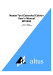
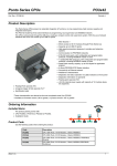
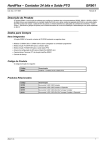
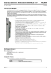
Micro Controller Doc. Code: CE110100 GR3xx Revision: E Product Description The Serie GR3xx provides our smallest and most economical programmable controllers. Their characteristics make them ideal solutions for medium and small application, including control task in machines and process that involves position and analogue interface. The I/O options provide great flexibility and can be expand with up to 56 I/O points. The GR3xx micro controller has the maximum main features: • 14 Digital inputs – 24 Vdc • 8 Transistor outputs • 2 Relay outputs • 4 Analogue inputs – 0 to 10 Vdc, 2 of them support thermocouple type J or K • 2 Analogue outputs – 0 to 10 Vdc • 2 High speed outputs with frequency up to 20KHz • 1 High speed counter, 24 bits resolution, up/down, up to 20 KHz, 12 operation modes that allows the use of transducers and position encoders • Interruption input • HardFlex architecture – extremely flexible architecture that allows reprogramming of high-speed hardware functions • Set points keyboard • Expand with up to 1 I/O module • Native Modbus RTU protocol (slave) • LEDs indicators show I/O status • Automatic addressing to expand modules • On line programming • PID Algorithm • Real Time Clock Module • Retentive bit memory without battery necessity • Great memory capacity with high performance • Serial communication port includes Modbus or Alnet I protocols • Diagnostic information available on runtime software and application program • Identification cards to I/O signals • Mounted on DIN TS35 rail HARDFLEX Architecture : a characteristic that allows reprogramming of high speed hardware functions. It is ideal to solve complex and time critical process on machines and great speed applications. Altus can provide library functions and, under consulting, develop new library functions. These functions not only can be used to execute specific applications with counters and high speed outputs, but also logical I/O operations. For further information see HardFlex Technical Characteristics documentation. Ordering Information Included Items The product packing comes with: • Micro Controller • Installation Guide Altus S. A. 1 Micro Controller GR3xx Doc. Code: CE110100 Revision: E Product Code Use the following codes when ordering the product: Code Description GR310 6DI 4DO Micro Controller GR316 10DI 6DO Micro Controller GR330 14DI 10DO Micro Controller GR350 14DI 12DO Counter Micro Controller GR351 14DI 12DO Counter Expansion Micro Controller GR370 14DI 12DO 4AI 2AO Thermocouple Counter Micro Controller GR371 14DI 12DO 4AI 2AO Thermocouple Counter Expansion Micro Controller Related Products Depending on your system requirements, the following products might be ordered along with the GR3xx. Code Description AL-1714 RJ45-RJ45 Cable AL-1715 RJ45-CFDB9 Cable AL-1718 RJ45-CMDB9 Cable AL-1719 RJ45-CMDB9 Cable AL-1720 RJ45-CMDB9 Cable AL-1721 RJ45-CMDB25 Cable AL 1726 RJ45-CFDB9 Cable AL 1413 RS232 / RS485 Transceiver AL 1518 24 Vdc/ 5 A Power Supply GR380 Real Time Module GR381 Expansion Cable GR900 HardFlex, 1 fast counter 2 frequency outputs GR901 HardFlex, 1 fast counter 1 PTO output GR902 HardFlex, 1 fast counter 1 PWM output PO9901 WebGate Plus PO8522 Block rail TS35 PO8523 Spring Terminal Tool FT1 Operator Panel FT3 Operator Panel FT5 Operator Panel FT10 Operator Panel QK1500 TS32/35 MT4100 MasterTool Programming Software Notes: AL-1714: Cable to connect a serial communication interface (Modbus or Alnet I, peer to peer) to CPU from Serie Ponto, Piccolo or Grano. Assembled with two RJ45 male connectors. AL-1715: Cable assembled with one RJ45 serial connector and one RS232 9-pin male sub-D connector IBM/PC standard. It is used on COM1 to connect the following equipment: • IHMs, which uses IBM/PC standard connector, to local supervision process • IBM/PC standard microcomputer to supervision software. • IBM/PC standard microcomputer to UCP programming port, through MasterTool Software AL-1718: Cable assembled with one RJ45 serial connector and one RS232 9-pin male sub-D connector Altus standard. It is used on COM1 to connect the following equipment: • AL-1413 module, RS232 / RS485 Transceiver Altus S. A. 2 Micro Controller GR3xx Doc. Code: CE110100 Revision: E AL-1719: Cable assembled with one RJ45 serial connector and one RS232 9-pin male sub-D connector Altus standard. It is used on COM1 to connect the following equipment: • IHM Foton 5 or Foton 10 AL-1720: Cable assembled with one RJ45 serial connector and one RS232 9-pin male sub-D connector Altus standard. It is used on COM1 to connect the following equipment: • IHM Foton 1 or Foton 3 AL-1721: Cable assembled with one RJ45 serial connector and one RS232 9-pin male sub-D connector Altus standard. It is used on COM1 to connect the following equipment: • Modem AL-1726: Cable assembled with one RJ45 serial connector and one RS232 9-pin female sub-D connector IBM/PC standard. It is used on COM1 to connect the following equipment: • PO9900 Webgate or PO9901 Webgate Plus GR380: Real time clock module, which can be used with the micro controller GR350, GR351, GR370 e GR371 GR381: Cable assembled with two female connectors to connected expansion modules. GR900: HardFlex characteristic that allows the use of fast counter application on micro controller GR350, GR351, GR370 e GR371. GR901: HARDFLEX characteristic that allows the use of fast counter application and fast pulse output. It includes the option of acceleration and deceleration ramp to motion control applications. GR902: HardFlex characteristic that allows the use of fast counter application and fast PWM output. It includes the option of acceleration and deceleration ramp to motion control applications. PO9901: It allows the connection of Altus CPs on Ethernet TCP/IP net. FT1 / FT3, FT5 / FT10: IHM interface used with Altus CPs through serial port by Alnet I protocol. Altus S. A. 3 Micro Controller GR3xx Doc. Code: CE110100 Revision: E Functional Characteristics GR310 GR316 GR330 GR350 GR351 GR370 GR371 Digital Inputs 6 10 14 14 14 14 14 Transistor outputs 4 4 8 8 8 8 8 Relay outputs 0 2 2 2 2 2 2 High speed outputs 0 0 0 2 2 2 2 Counters 0 0 0 1 (24 bits) 1 (24 bits) 1 (24 bits) 1 (24 bits) Interruption input 1 1 1 1 1 1 1 Analogue inputs 0 0 0 0 0 4 4 Analogue inputs with thermocouple 0 0 0 0 0 2 2 Analogue outputs 0 0 0 0 0 2 2 No No No Yes Yes Yes Yes Maximum module expansions 0 0 0 0 1 0 1 Maximum I/O points with expansions 10 16 24 24 56 24 56 Modbus protocol (slave) No No Yes Yes Yes Yes Yes Application program memory – Flash type (bytes) 8K 8K 16 K 32 K 32 K 32 K 32 K Application program memory – RAM type 8K 8K 16 K 32 K 32 K 32 K 32 K Retentive bit memory (words 16 bits) 16 16 32 32 32 32 32 Total memory amount for operands 1K 1K 4K 8K 8K 8K 8K Floating point math operation No No No Yes Yes Yes Yes Real time clock module GR380 Keyboard Serial interfaces HardFlex Architecture MasterTool Programming MT4100 or MT4000 Yes Yes Yes Yes Yes Yes Yes 1x RS232 1x RS232 1x RS232 1x RS232 1x RS232 1x RS232 1x RS232 No No No Yes Yes Yes Yes 3.51 or greater version 3.60 or greater version Notes: Counters: the standard product has 1 counter with 24 bits resolution and 12 counter modes. Different configuration can use HardFlex architecture functions, which can be provide by consulting. Counter Inputs: the counter and digital input use the same connection, I1 to I4 inputs. The user can choose how to use the connection, counter or digital functions. High Speed Outputs: the modules that use this characteristic are supply with the HardFlex GR900, that allows the use of two outputs with frequency up to 20 KHz. These outputs can be configure with other characteristics according to different HardFlex configurations. Optionally the outputs can be used like common digital low current. Interruption Input: the digital and interruption input use the same connection, I0 input. With the use of E-020 module, on application program, the input will be set to positive edge interrupt. Otherwise the input will be set like common digital input. Expansion Modules: the GR351 and GR371 can be used like expansion modules. The expansion executes a different application program (Ladder), that changes information through a expansion bus with high speed characteristics. Real Time Clock Module: The GR380 module allows this characteristic. MasterTool: The Serie Grano is programmed by any MasterTool with hardkey upper than 3.51 version, including MasterTool PL. HardFlex Architecture: The modules which permit the use of HardFlex architecture comes with native GR900 version. Versions with different solutions are available to order. Altus S. A. 4 Micro Controller GR3xx Doc. Code: CE110100 Revision: E General Characteristics GR310, GR316, GR330, GR350, GR351, GR370, GR371 Status and diagnostic LEDs indicators EX, PG, ER, DG, AI,TR On line programming Yes Typical program scan time 1,6 ms / Kwords RS232 Communication port (COM 1) TX, RX, RTS and CTS Maximum analog I/O points Limited by the availability of UCP and expansion modules analog channels Power supply protection Polarity inversion Watchdog Yes Terminal and Connector Configuration 1 RJ45 connector (COM 1) External power supply 19 to 30 Vdc including ripple Isolation voltage from logical circuit No isolation between user and system Maximum power consumption 150 mA Power dissipation with full load 3,6 W Standards IEC 61131 Weight 200 g Operating temperature 0 to 60 C Dimensions (W x H x D) mm 100 x 127 x 54 One LED by I/O point Spring terminals to field wiring connection o Serial Port The GR3xx micro controllers have a optimal communication capability, that provides a wide range of communication features. It allows the communication among several equipment by Alnet I V2.0 or Modbus RTU protocols. The communication rates for the serial port are the following: Communication Rate (bps) ALNET I 9600, 4800, 2400, 1200, 600, 300 MODBUS 19200, 9600, 4800, 2400, 1200, 600, 300 The serial port allows the connection of modems or radio modems that use RTS and CTS signals. In addition, the PO9901 – WebGate Plus module adds an Ethernet port to the Serie Grano. This port provides communication capabilities that let the GR3xx UCP communicate with other Altus controllers, interfaces and runtimes software. Runtime Software or IHMs Communication Altus S. A. 5 Micro Controller GR3xx Doc. Code: CE110100 Revision: E IHMs or Runtime COM 1 RS232 GR3xx MasterTool MODBUS Remote Communication Serie PONTO UCP PO3242 AL1413 MODBUS Net RS485 Altus S. A. AL1413 GR3xx GR3xx 6 Micro Controller GR3xx Doc. Code: CE110100 Revision: E Ethernet Communication The GR3xx micro controllers can be connected to an Ethernet net providing remote data acquisition and control functions. The UCP can be accessed by runtime software or browser allowing remote programming and I/O pass thru commands. Further more it is possible to communicate with other controller to interlocking commands. Runtime Software Browser Browser Runtime PO7091 e PO3342 PO9901 GR3xx AL-3405 e AL-200x PO7091 e PO3242 HardFlex Architecture The HardFlex Architecture, which is native in some Serie Grano models, provides a flexible and capable structure with hardware reprogramming functions. This architecture allows the programming of specific functions according with user necessities to fill a process lack. It helps the communication between HardFlex CP and equipment with different communication standards. There are machines, sensors and transducers that have the same functions but use different communications standards, according to each manufacturer. HardFlex Architecture comes to bond and facilitate machine communication standard where the code and decode communication function is installed on CP. An example of this case can be find when the user purchases a transducer to position control. Supposing that the purchased transducer is the best for his application, but it comes with an uncommon signal. A CP to decode or code this signal can be expensive, difficult to find or will be necessary the development of special circuits to adjust the signal. It is possible with the use of CPs Grano a hardware reprogramming then the uncommon standard will be decode and process by the CPU. Also it exists the possibility to use functions with high speed outputs like PWM (Pulse Wide Modulation), PTO (Pulse Train Output), and other for closed control loop. Altus S. A. 7 Micro Controller GR3xx Doc. Code: CE110100 Revision: E Digital Inputs GR310, GR316, GR330, GR350, GR351, GR370,GR371 Digital input model 24 Vdc sink digital input, not isolated Input voltage 24 Vdc nominal 15 to 30 Vdc for 1 signal 0 to 5 Vdc for 0 signal Input current 4,2 mA @ 24 Vdc Input impedance 5,7 kΩ Terminal block configuration I0 to I7 (%E0) J0 to J5 (%E1) Input type Type 1, switches and 2 wire sensors Input delay time 2 ms @ 24 Vdc (typical) Isolation from logical circuit No isolation between user and system Status Indicator One LED by input point Relay Outputs GR316, GR330, GR350, GR371 Relay output model 2 relay outputs, dry contact, normally open 3 A @ 5 a 30 Vdc 0,5 A @ 48 Vdc Resistive load 0,150 A @ 125 Vdc 1,5 A @ 125 Vac 1,5 A @ 240 Vac Contact resistance Maximum 100 mΩ Isolation from logical circuit 1500 Vac for 1 minute, 250 Vac continuos Minimum contact load 10 mA @ 12 Vdc Terminal block configuration R0 – R0 dry contact R1 – R1 dry contact Expected life Operate / release Time Altus S. A. 6 10. 10 operations with nominal load 7,5 ms to close 8,5 ms to open Switching frequency Maximum 0,5 Hz with nominal load Status indicator One LED by output point 8 Micro Controller GR3xx Doc. Code: CE110100 Revision: E Transistor Outputs GR310, GR316, GR330, GR350, GR351, GR370, GR371 Transistor output model Output current 8 transistor source outputs, 24 Vdc, not isolated 1A with all points on 2 A with only one point on by group of 4 Terminal block configuration T0 to T7 Maximum output impedance 200 mΩ Output signal delay Maximum 300 us Switching frequency Maximum 500 Hz Isolation from logical circuit No isolation between user and system Protection Short circuit and over current Diagnostic indicator Over current cutoff voltage Status indicator One LED by output point High Speed Outputs GR350, GR351, GR370, GR371 High speed output model 2 source outputs, not isolated Minimum voltage output 20 Vdc @ 24 Vdc power supply Output modes PTO (Pulse Train Output) Mode PWM (Pulse Wide Modulation) Mode VF ( Variable Frequency ) Mode Output current 16 mA source with RL = 1,5 kΩ Terminal block configuration F0 and F1 – HardFlex outputs or bits 2 and 3 from second output octet Switching frequency 0 to 20 kHz Protection Short circuit Isolation from logical circuit No isolation from user and system Diagnostic indicator Short circuit Notes: It is suggest the use of an external impedance of 1,5 kΩ. These outputs can be used for: • Stepper motor control position • Connection to converter blocks F/V (frequency / voltage) increasing analog output capacity Not only standard functions can be set to high speed outputs but also new functions with special characteristics that changes the hardware behavior. New functions modules can be supply (under consulting) for complex high speed application and time critical functions. Altus S. A. 9 Micro Controller GR3xx Doc. Code: CE110100 Revision: E Counter Inputs GR350, GR351, GR370, GR371 Counter input model 1 high speed counter, up/down, 24 bits Voltage input 15 to 30 Vdc for 1 signal Counter modes 12 counter modes Terminal block configuration I1 to I6 – HardFlex inputs or common digital inputs without filter Input impedance 5,7 kΩ Isolation from logical circuit No isolation from user and system Switching frequency 0 to 20 kHz 0 to 5 Vdc for 0 signal • • • • Notes: Not only standard functions can be set to high speed outputs but also new functions with special characteristics that changes the hardware behavior. New functions modules can be supply (under consulting) for complex high speed application and time critical functions. These outputs can be used for: Special fast counters Time difference between inputs Frequency converter to digital value, increasing analog capacity through converter V/F blocks It is available 6 high speed counter inputs, 4 set to factory configuration with 24 bits counter and 2 reserved for optimized functions. The high speed counter inputs and common digital inputs use the same terminals which will be set according application. Attention: In case of high speed counter and high speed output configuration see HardFlex GR9xx Technical Documentation for further information. Altus S. A. 10 Micro Controller GR3xx Doc. Code: CE110100 Revision: E Analog Inputs GR370, GR371 Analog input model 4 analog inputs, not isolated ± 0,2 % Full scale @ 25 C o Accuracy ± 0,01% Full scale / C o Resolution 12 bits linearity guarantee Input impedance 1,3 MΩ (Voltage input) 13 kΩ (Two thermocouple inputs) Filter 2 ms, 150 ms, 1.2 s , 10 s configurable by software Maximum voltage without damage +12 V Isolation from logical circuit No isolation between user and system Terminal block configuration A0 and A- , A1 and A-, A2 and A- , A3 and A- Crosstalk DC a 100 Hz -72 dB min Scale Measurement scale loose Range Steps Resolution 0 to 10 Vdc 0 to 30.000 2,6 mV up to 5% above the maximum limit Scanning time 10 ms Measurement loose if 5% above the maximum limit Diagnostic Indicator Over range Notes: Two analog inputs can be used for temperature measurement with thermocouples. The filtering parameterization is set by software according available values. It is resolve by software and simulated time constant RC analogue filter. Altus S. A. 11 Micro Controller GR3xx Doc. Code: CE110100 Revision: E Thermocouple Input GR370, 371 Thermocouple input model 2 Thermocouple inputs. Thermocouple must be isolated Accuracy ± 0,4 % Full scale @ 25 C o ± 0,01% Full scale / C o Resolution 12 bits linearity guarantee Temperature Unit Configurable: C or F Input impedance 13 kΩ Maximum voltage without damage +12 Vdc Filter 400 ms, 1 s or 10 s configurable by software Terminal block configuration A0 e A- , A1 e A- Cold junction compensation range Temperature sensor o o o Compensation range: temperature environment at 80 C Precision ± 5 C o Scanning time 100 ms Isolation from logical circuit No isolation between user and system Initial temperature Ti = environment temperature Supported thermocouple ºC ITS-90 Graphic Supported thermocouple ºF ITS-90 Graphic Model Temperature J Ti to 750 C o o Step Resolution 0 a 7500 0,5 C o o K Ti to 1250 C 0 a 12500 0,5 C Model Temperature Step Resolution J Ti to 1382 ºF 320 a 13820 1 ºF K Ti to 2282 ºF 320 a 22820 1 ºF Scale loose up to 5% above the maximum limit Diagnostic Open circuit Over range Notes: The thermocouple must be isolated, without machine contact. The terminal A- must be used only for analog input with negative signal polarity. The terminals A0, A1, A2 e A3 must be connected to positive signal voltage. Temperature: the thermocouple must be connected only on A0 – A- e A1 – A-. The terminals A- must be connected to a negative polarity. The temperature is measured over the initial temperature. Altus S. A. 12 Micro Controller GR3xx Doc. Code: CE110100 Revision: E Analog Outputs GR370, GR371 Analog output model 2 analog outputs, not isolated ± 0,2 % Full scale @ 25 C o Accuracy ± 0,01% Full scale / C o Terminal block configuration P0 e P- , P1 e P- Scale Output current Range Step Resolution 0 to 10 Vdc 0 to 30.000 2,6 mV 5 mA typical with RL = 2 kΩ Resolution 12 bits Scanning time 12 ms Scale loose Minimum 4% Isolation from logical circuit No isolation between user and system Protection Short circuit Real Time Clock Module The real time clock module is an optional item and must be buy independently because it can be used only in some modules. GR380 Altus S. A. Real time clock module Clock to count second, minute, hour, month, day, day of week and year Resolution One second Leap year Automatic until 2100 year Maximum Error One minute / month @ 25 ºC Clock backup Lithium battery Battery life expect 4 years or more @ 25 ºC Operating Temperature 0 to 60 ºC 13 Micro Controller GR3xx Doc. Code: CE110100 Revision: E Software Characteristics GR310, GR316, GR330, GR350, GR351, GR370, GR371 Programming language Diagram and logic blocks, structured in modules with functions and sub-routines On line programming COM 1 Input (E) and output (S) operands 256 Auxiliary operands (bits) 512 Numeric operands memory (words 16bits) 1 Kbytes on GR310 1 Kbytes on GR316 4 Kbytes on GR330 8 Kbytes on GR350 and GR351 8 Kbytes on GR370 and GR371 Available operands M memory 16 bits (some models do not use floating point operands) D BCD 32 bits F floating point TM memory table TD BCD table TF floating point table KM 16bits constant KD BCD constant KF floating point constant Typical memory occupation by contact instruction 7 bytes Notes: All numeric operands (KM, KD, M, D, TM, TD and TF) allow values representing with arithmetic signal. The application program configures the number of simple operands and tables (M, D, TM, TD and TF), which it is limited by the available operands memory capacity (see comparative table). Altus S. A. 14 Micro Controller GR3xx Doc. Code: CE110100 Revision: E Instruction List Instruction -|/|- : Close relay (examine if close) -| |- : Open relay (examine if open) Relay Contact PSL : Pulse relay RM : Master relay FRM : Master end relay -( )- : Single relay coil output -(L)- : Energize relay coil output -(D)- : De-energize relay coil output -(S)- : Jump relay coil output Data Handling Comparison Arithmetic Conversions Binary operations Counting Timing Indexed Sub routines Altus S. A. MOV : Simple operand movement MOP : Operand block movement MOB : Operand block movement MOT : Table movement CAB : Block charge CAR : Operand charge = : Equal < : Less than > : Bigger than + : Addition - : Subtraction / : Division x : Multiplication B/D : Binary decimal conversion D/B : Decimal binary conversion AND : Binary AND OR : Binary OR XOR : Binary XOR NEG : NOT operator CON : Simple counter COB : Up / down counter TEE : Timer on-delay TED : Timer off-delay LDI : On/off indexed points TEI : Status test for indexed points SEQ : Sequence CHF : Function module call CHP : Procedure module call 15 Micro Controller GR3xx Doc. Code: CE110100 Revision: E Module Functions List Function Modules Description F-PID.033 PID algorithm function. F-RAIZN.034 Square root for memory or real operand. In case of memory operand the result can be normalized for a previously scale. F-ARQ2.035 F-ARQ4.036 F-ARQ8.037 F-ARQ12.038 It allows the storage for large data quantities, using register and fields concepts. F-ARQ15.039 F-ARQ16.040 F-ARQ24.041 Altus S. A. F-MOBT.043 Improve block copies between numeric and table operands. F-STCP.044 CP status operands F-CTRL.059 Improve lead / lag algorithms . F-PID16.056 Improve proportional, integral and derivative controlling (it has some differences from F-PID.033). F-NORM.071 Operand normalizes function. F-COMPF.072 Compare operands according a range. F-AES.087 Executes an immediately scanning of I/O points with image memory actualization and specified physical positions. F-ANDT.090 Improve logical operation AND between simple operands (M or D) and/or tables (TM or TD). It can be perform up to 255 logical operations with one unique function call. F-ORT.091 Improve logical operation OR between simple operands (M or D) and/or tables (TM or TD). It can be perform up to 255 logical operations with one unique function call. F-XORT.092 Improve logical operation XOR between simple operands (M or D) and/or tables (TM or TD). It can be perform up to 255 logical operations with one unique function call. F-NEGT.093 Improve logical operation NOT between simple operands (M or D) and/or tables (TM or TD). It can be perform up to 255 logical operations with one unique function call. F-M_F.050 Convert two round number to floating point value. F-F_M.051 Convert floating point value to two round numbers. F-FSOM.052 Floating point addition. F-FSUB.053 Floating point subtraction. F-FMUL.054 Floating point multiplication. F-FDIV.055 Floating point division. 16 Micro Controller GR3xx Doc. Code: CE110100 Revision: E UCPs F-PID.033 GR370, GR371 F-RAIZN.034 GR310, GR316, GR330, GR350, GR351, GR370, GR371 F-ARQ2.035 F-ARQ4.036 F-ARQ8.037 F-ARQ12.038 Related Products GR330, GR350, GR351, GR370, GR371 F-ARQ15.039 F-ARQ16.040 GR350, GR351, GR370, GR371 F-ARQ24.041 F-MOBT.043 F-STCP.044 F-CTRL.059 F-PID16.056 GR310, GR316, GR330, GR350, GR351, GR370, GR371 F Modules available within MasterTool Programming GR370, GR371 F-NORM.071 F-COMPF.072 F-AES.087 F-ANDT.090 F-ORT.091 GR310, GR316, GR330, GR350, GR351, GR370, GR371 F-XORT.092 F-NEGT.093 F-M_F.050 F-F_M.051 F-FSOM.052 F-FSUB.053 GR310, GR316, GR330, GR350, GR351, GR370, GR371 F Module available within AL-2700 function package F-FMUL.054 F-FDIV.055 Note: The functions not included on MasterTool Programming can be purchased separately. Altus S. A. 17 Micro Controller Doc. Code: CE110100 GR3xx Revision: E Terminal Connection The following pictures illustrate the electric diagram connection for Serie Grano. Altus S. A. 18 Micro Controller Doc. Code: CE110100 Altus S. A. GR3xx Revision: E 19 Micro Controller Doc. Code: CE110100 Altus S. A. GR3xx Revision: E 20 Micro Controller Doc. Code: CE110100 Altus S. A. GR3xx Revision: E 21 Micro Controller Doc. Code: CE110100 GR3xx Revision: E Notes 1- The power supply common point (0 V) must be connected to electrical panel grounding . This connection is suggested to minimize electrical noise on the automation system. 2- The power supply must be connected to + (+24 Vdc) and - (0 V) terminal module, according to electrical diagrams. The power supply must be projected to support the micro controller load, input components (sensors) load and output components load. 3- The T+ terminals drive energy to transistor outputs and must be connected to +24 Vdc power supply. It is suggest the use of protection circuits to reduce electrical noise and assure output operation. 4- The digital inputs work with sensors that use PNP output (positive switching) or dry contacts. It can be used sensors with two or three wires. The sensors must be connected to any I0 and I7 or J0 and J5 terminal. The negative terminal of the three wire sensors must be connected to any I- terminal. The sensors must supply correctly signal according to micro controller specification. 5- It is necessary the use of protection circuits when loads are actuated by relay contacts. 6- The thermocouple measurement must be done by the connection of positive pole to A0 and A3 terminals and the negative pole to A-. The environment temperature compensation – cold junction – is made automatically by native module sensor. In case of open thermocouple junction the values will go to end of scale, which it will activated the open thermocouple diagnosis. 7- In case of voltage measurement the positive pole must be connected to A0 and A3 terminals and the negative pole to Aterminals, which are common for all inputs. The micro controller only measures positive voltages. If any negative voltage is driven in the inputs, they will be short circuited by a diode with the 0 Vdc. In this case the value will be zero. 8- The voltage outputs have the positive pole connected to P0 and P1. The negative pole is connected to A terminal, which is common for the two outputs. The P- terminal is internally connected to 0 Vdc. 9- It is suggest the use of shielded cable when using thermocouple measurement. The thermocouples cables must be grounded in one extremity and most near from module terminal connection. 10- The three terminals C are short circuited, providing different points to connections. 11- The analog input signals must be grounded only in one extremity and most near from module terminal connection 12- The analog output signals must use shielded cable. The cables must be grounded in one extremity and most near from module terminal connection. 13- The models that allows modules expansion are connected by the expansion cable GR381. Altus S. A. 22 Micro Controller GR3xx Doc. Code: CE110100 Revision: E Physical Dimensions 6 1 .8 mm dimensions 030 5290 0A 1 1 6 .6 2 8 .0 1 2.4 9 9.0 Manuals For correct application and utilization the User’s Manual must be consulted. For further technical details, configuration, installation and programming of Serie Grano products please consult following documents:: Altus S. A. Document code Description MU210000 Serie Grano User’s Manual MAN/MT4100 MT4100 User’s Manual 23