1
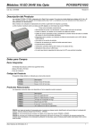
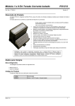
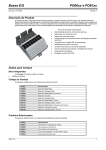
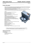
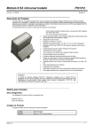
16 DI 24/48 Vdc Opto Modules
PO1000/PO1003
Doc. Code: CE109300
Revision: E
Product Description
The PO1000 and PO1003 modules are part of the Ponto Series and each module has 16 opto isolated 24 Vdc or 48 Vdc digital
inputs. The modules use positive logic (“sink”) and they are ideal solutions for control and supervision process.
The picture shows the product assembled in a base for digital I/O with spring terminal blocks. The main features are:
• High density of I/O with feeding and return for each individual input.
• Hot swap, no interference on panel cabling.
• Field cabling is directly connected to the base, thus eliminating need for intermediary terminal
• blocks.
• Remote and local diagnosis, with indication for no communication with CPU and failure on
external power supply.
• Protection of all inputs through one fuse assembled in the base PO6103.
• Automatic addressing.
• Automatic verification of module type by the bus head.
• Status operation via LEDs indicators.
• A input can interrupt the CPU for immediate processing.
• Identification tag.
.
Ordering Information
Included Items
The product packing comes with:
• PO1000 or PO1003 Module
• Installation Guide
Product Code
Use the following codes when ordering the product.
Code
Description
PO1000
16 DI 24Vdc Opto Module
PO1003
16 DI 48Vdc Opto Module
Related Products
Depending on your system requirements, the following products might be ordered along with the PO1000.
Code
Description
PO6000
Spring Digital I/O base
PO6100
Spring Digital I/O base with fuse
PO8522
End bracket for rail
PO8523
Spring terminal tool
PO8520
16 Fuse 3 A – spare part
Altus Sistemas de Informática S. A.
1
16 DI 24/48 Vdc Opto Modules
PO1000/PO1003
Doc. Code: CE109300
Revision: E
Features
PO1000
Module type
16 24Vdc sink digital input
Input voltage
24 Vdc (15 to 30 Vdc including ripple)
15 to 30 Vdc; status 1
0 to 5 Vdc; status 0
Input current
3 mA (24 Vdc)
Input type
Type 1, for switches and sensors with 3 wires
Input impedance
8 KOhm
Filtering
2 ms
Terminal block configuration
One terminal block for external supply and one terminal block by
input
Input delay time
2 ms
Status indication
One LED by input point
Diagnosis indication
One multifunctional LED with module OK indication, not accessing
module, open fuse and input failure
Configurable parameters
External power supply missing
Input self testing
Hot swap
Yes
Protection
One 300 mA fuse for protection of all inputs.
External 3A fuse for power supply protection for each input point,
when PO6100 is used.
Power supply Inversion polarity protection
External power supply
19 to 30 Vdc, including ripple, for input feeding.
Positive on 'A ' terminal and Negative on ' B ' terminal.
Isolation
Inputs to ground
1500 Vac, 1 minute, 250 Vac continuos
Inputs to logic circuit
1500 Vac, 1 minute, 250 Vac continuos
Among inputs
No isolation
Bus current consumption
80 mA
Power dissipation
1,3 W with all points activated (usual)
1,7 W with all points activated (maximum)
0,6 W with all points off
o
Maximum operating
temperature
60 C
Dimensions
100 x 52 x 84 mm
Standards
- IEC 61131-2:2003, clauses 8 and 11
- CE, EMC and Low-Voltage (LVD) Directives.
Bases
PO6000, PO6100
Protection: an internal thermo devide fuse is used to protection all input signals. After the overload or short-circuit the device
recover the normal operation.
Self Test: all input points may be automatic tested by the system. This characteristic is enable by the user in the configuration
step. If enable, the all points will be tested each 6 seconds, during 4 miliseconds. During the test time, the module will freeze
the last input datas. The input LEDs will flash during this time too.
Power supply interruptions: Interruptions in power port are supported if not longer than 10 ms and if the module is powered
with it’s nominal 24 Vdc voltage or greater. Longer interruptions or in voltages lower than the nominal may cause modules
reset.
Altus Sistemas de Informática S. A.
2
16 DI 24/48 Vdc Opto Modules
PO1000/PO1003
Doc. Code: CE109300
Revision: E
PO1003
Module type
16 48Vdc sink digital input
Input voltage
48 Vdc ( 34 to 60 Vdc includding ripple )
34 to 60 Vdc; status 1
0 to 10 Vdc; status 0
Input current
3 mA (48 Vdc)
Input type
Type 1, for switches and sensors with 3 wires
Input impedance
16 KOhm
Filtering
2 ms
Terminal block configuration
One terminal block for external supply and one terminal block by
input
Input delay time
2 ms (usual)
Status indication
One LED by input point
Diagnosis indication
One multifunctional LED with module OK indication, not accessing
module, open fuse and input failure
Configurable parameters
External power supply missing
Input self testing
Hot swap
Yes
Protection
One 300 mA fuse for protection of all inputs.
External 3A fuse for power supply protection for each input point,
when PO6100 is used.
Power supply Inversion polarity protection
External power supply
38 to 60 Vdc, including ripple, for input feeding.
Positive on 'A ' terminal and Negative on ' B ' terminal.
Isolation
Inputs to ground
1500 Vac, 1 minute, 250 Vac continuos
Inputs to logic circuit
1500 Vac, 1 minute, 250 Vac continuos
Among inputs
No isolation
Bus current consumption
80 mA
Power dissipation
1,9 W with all points activated (usual)
2,8 W with all points activated (maximum)
0,6 W with all points off
o
Maximum operating
temperature
60 C
Dimensions
100 x 52 x 84 mm
Standards
- IEC 61131-2:2003, clauses 8 and 11
- CE, EMC and Low-Voltage (LVD) Directives.
Bases
PO6000, PO6100
Protection: an internal thermo devide fuse is used to protection all input signals. After the overload or short-circuit the device
recover the normal operation.
Self Test: all input points may be automatic tested by the system. This characteristic is enable by the user in the configuration
step. If enable, the all points will be tested each 6 seconds, during 4 miliseconds. During the test time, the module will freeze
the last input datas. The input LEDs will flash during this time too.
Power supply interruptions: Interruptions in power port are supported if not longer than 10 ms and if the module is powered
with it’s nominal 24 Vdc voltage or greater. Longer interruptions or in voltages lower than the nominal may cause modules
reset.
Altus Sistemas de Informática S. A.
3
16 DI 24/48 Vdc Opto Modules
PO1000/PO1003
Doc. Code: CE109300
Revision: E
Installation
ATTENTION:
ESD (Electro Static Discharge) sensitive device. Always touch a grounded metallic object before handling
the device.
Electrical Installation
The following diagram shows the cabling for 2 sensors on the PO1000 module installed on the PO6100 base. The same
configuration applies to the PO1003.
5
6
Module
PO1000
Base
PO6100
To other
modules
A
-
20
40
+
8
2 Wire Sensors
POINTS
FUS00
00
00
FUS01
1
21
01
01
41
FUS02
22
02
02
42
FUS03
3 Wire Sensors
+
P
23
03
03
43
FUS04
24
04
04
44
FUS05
25
05
05
45
+
P
2
26
FUS07
27
24Vdc
9
06
06
46
07
07
47
FUS10
30
10
10
50
FUS11
31
11
11
51
FUS12
32
12
12
52
Opto isolation
FUS06
FUS13
33
13
13
53
FUS14
34
14
14
54
FUS15
15
15
55
FUS16
36
16
16
56
FUS17
4
37
17
17
57
01092700
35
0V
GND
B
-
+
To other
modules
7
To next
m odule
3
Altus Sistemas de Informática S. A.
4
16 DI 24/48 Vdc Opto Modules
PO1000/PO1003
Doc. Code: CE109300
Revision: E
Diagram notes:
1 - Sensors with 2 wires should have connected on the terminal blocks numbered from 00 to 17 and 20 to 27.
2 - Power supply for the field sensors. The power supply must be connected to the A (+24/48 Vdc) and B inputs for each base, as
shown on the diagram. The power supply must guarantee an energy output within the module requirements.
3 - O The power supply common point for the field sensors (0V) should be connected to the panel grounding. This connection is
not mandatory, but it is highly recommended in order to reduce electrical interference in automation systems.
4 - O This connection is required when the diagnosis of no voltage for field sensors are needed.
5- The terminal blocks ( + ) and ( - ) can be used for feeding of other modules of the bus. The PO1000 and PO1003 do not use
this terminals blocks.
6 - The power supply common point for the module (0V) should be connected to the panel grounding. This connection is not
mandatory, but it is highly recommended in order to reduce electrical interference in automation systems..
8 – In case of necessity of individual input protection, use fast fuses with maximum value of 250 mA in accordance to the
electrical project specifications.
ATTENTION:
Each Ponto module use a particular connection to A and B terminal blocks. In this case the terminal B
is connected to 0 Vdc and the terminal A is connected to 24 +Vdc.
The terminal blocks identification follow direct relation to the I/Os and LEDs as shows below::
Module Input
00
01
02
03
04
05
06
07
10
11
12
13
14
15
16
17
Input terminal
00
01
02
03
04
05
06
07
10
11
12
13
14
15
16
17
Common terminal
40
41
42
43
44
45
46
47
50
51
52
53
54
55
56
57
20
21
22
23
24
25
26
27
30
31
32
33
34
35
36
37
( 0 Vdc)
+24 or +48 Vdc
terminal
ATTENTION:
Atmospheric discharges (thunders) may cause damages to the modules although it’s protections.
Additional protections should be used if module’s power comes from a power supply located outside
the cabinet where the module is installed, because it could be vulnerable to this kind of discharges.
If the field wiring of the input points is susceptible to this kind of discharge, surge suppressors should
be used.
Mechanical Assembly
The mechanical assembly is described in the Ponto Series Utilization Manual.
Please adjust the mechanical code on the assembly base to 0 (zero) on switch A and 0 on switch B for the PO1000 and 0 (zero)
on switch A and 3 on switch B for the PO1003.
Altus Sistemas de Informática S. A.
5
16 DI 24/48 Vdc Opto Modules
PO1000/PO1003
Doc. Code: CE109300
Revision: E
Parameterization
The CPU or field network head defines via software the PO1000/PO1003 parameterizations. Such parameterization may be set by
the MasterTool when using Altus CPUs or by the software that configures the field bus master. For further information please
consult Ponto Series Utilization Manual, MasterTool Utilization Manual and Manuals for the Interfaces and Field Network Heads.
The parameterization is set through user-friendly menus. For reference purposes, following are the binary codes.
Parameters Bytes
The PO1000 and PO1003 modules are defined by 1 byte.
Byte
0
Byte 0 – General
7
6
Parameters
General
Description
5
4
3
2
1
0
0
0
0
0
0
1
Number of parameters bytes ( always 1 )
Always zero
0
Self testing disable
1
Self testing enable
0
Power supply diagnosis disable
1
Power supply diagnosis enable
Diagnosis
Diagnosis Bytes
The PO1000/PO1003 modules have one byte for module operating diagnosis.
Byte
0
Byte 0 - General
7
6
5
0
Diagnosis
General
PROFIBUS Message
4
3
2
1
0
0
0
0
0
0
Description
-
Always zero
0
-
Input points OK
1
01
Hardware failure
0
-
External DC voltage on
1
02
External DC voltage off
Diagnostic LED
Altus Sistemas de Informática S. A.
6
16 DI 24/48 Vdc Opto Modules
PO1000/PO1003
Doc. Code: CE109300
Revision: E
This module diagnostic LED shows the following situations:
DG LED
Meaning
ON
Normal operation
Blinking 1X
Not accessed module or
logic problem
Causes
- Position with wrong type module
- Module not declared
- Module damaged
Blinking 3X
Blinking 4X
External DC voltage
missing
- External power supply with lower limit
Input point failure
- One or more input points damaged
- Open fuse
Physical Dimensions
Dimensions in mm.
Maintenance
The hot swap procedure is described in the Ponto Series User’s Manual.
Manuals
For further technical details, configuration, installation and programming of Ponto Series products please consult following
documents:
Document Code
Description
MU209000
User’s Manual – Serie Ponto
MAN/MT4100
Programming Manual – MT4100
Altus Sistemas de Informática S. A.
7