1
User Manual for Professional Firmware
AirStation NFINITI HighPower Router and AccessPoint
WHR-300HP
AirStation NFINITI HighPower Router and AccessPoint
WZR-300HP
AirStation NFINITI HighPower Router and AccessPoint
WZR-600DHP
www.buffalotech.com
1.
Introduction
1.1. Welcome
1.2. Device Configuration
1.2.1. Factory Settings
1.2.2. Initial Operation
2.
Configuration via the Web Interface
2.1. Preparation
2.2. Web Interface Access
2.3. Web Interface Structure
2.3.1. Setup
2.3.1.1. Basic Configuration
2.3.1.2. Dynamic DNS (DynDNS or DDNS)
2.3.1.3. MAC Address Cloning
2.3.1.4. Advanced Routing
2.3.1.5. Networking
2.3.1.6. EoIP Tunnel (WZR series only)
2.3.2. Wireless
2.3.2.1. Basic Settings
2.3.2.2. Wireless Security
2.3.2.3. AOSS/WPS
2.3.2.4. MAC Filter
2.3.2.5. WDS
2.3.3. Services
2.3.3.1. Services
2.3.3.2. FreeRadius (WZR series only)
2.3.3.3. PPPoE Server
2.3.3.4. VPN
2.3.3.5. USB (WZR series only)
2.3.3.6. NAS (WZR series only)
2.3.3.7. Hotspot
2.3.3.8. SIP Proxy (WZR series only)
2.3.3.9. My Ad Network
2.3.4. Security
2.3.4.1. Firewall
2.3.4.2. VPN Pass-through
2.3.5. Access Restrictions
2.3.5.1. WAN Access
2.3.6. NAT / QoS
2.3.6.1. Port Forwarding
2.3.6.2. Port Range Forwarding
2.3.6.3. Port Triggering
2.3.6.4. UPnP
2.3.6.5. DMZ
2.3.6.6. QoS
2.3.7. Administration
2.3.7.1. Management
2.3.7.2. Keep Alive
2.3.7.3. Commands
2.3.7.4. WOL
2.3.7.5. Factory Defaults
2.3.7.6. Firmware Upgrade
2.3.7.7. Backup
2.3.8. Status
2.3.8.1. Router
2.3.8.2. WAN
2.3.8.3. LAN
2.3.8.4. Wireless
-1-
3
3
3
3
3
4
4
4
5
6
6
7
7
7
8
8
8
8
10
11
12
12
13
13
13
13
13
14
14
15
15
15
15
15
15
15
15
15
15
16
16
16
16
16
16
16
17
17
17
17
17
17
17
17
17
18
18
2.3.8.5. Bandwidth
2.3.8.6. SysInfo
3.
Use Cases
3.1. Access Point
3.1.1. Access Point with NAT / DHCP
3.1.1. Access Point attached to a network / Internet gateway
3.2. Wireless Client
3.3. Wireless Client Bridge
3.4. FTP Server
3.4.1. Examples
3.4.2. Logging into the FTP server
3.4.3. Common FTP commands
3.5. Changing Firmware
4.
GPL Statement
4.1. GNU General Public License
4.1.1. Preamble
4.1.2. GNU General Public License – Terms and Conditions or Copying,
Distribution and Modification
4.1.3. NO WARRANTY
-2-
18
18
19
19
19
20
21
22
23
23
25
25
26
28
28
28
29
32
1. Introduction
1.1. Welcome
This AirStation wireless router comes with two different firmware
packages. You may use either the dd-wrt-based Professional firmware or
the simple User-friendly firmware. By default, the Professional
firmware is preinstalled for US/EU products, and the User-friendly
firmware is preinstalled for Asia-Pacific products.
If you're using the user-friendly firmware, please click on the link
on the left side.
1.2. Device Configuration
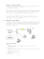
From the factory, the router is configured as a network bridge. That
means that all network interfaces can communicate with each other
using this default bridge. The router is ready to use with a few
simple adjustments.
1.2.1.
Factory Settings
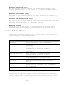
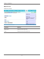
Because all interfaces are attached to the bridge by default, they all
have the same IP configuration:
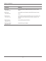
IP address
Subnet Mask
DHCP server
DHCP-Range
192.168.11.1
255.255.255.0
enabled
192.168.11.100 - 149
The default SSID settings are shown below.
WHR-300HP: BUFFALO + last 6 digits of MAC address
WZR-300HP: BUFFALO + last 6 digits of MAC address
WZR-600DHP: For 2.4 GHz BUFFALO + last 6 digits of MAC address + "_G"
For 5 GHz
BUFFALO + last 6 digits of MAC address + "_A"
In the default settings, the encryption system is set to WPA2-PSK/WPAPSK (TKIP + AES), and the 8-digit unique product number is set as the
encryption key.
1.2.2.
Initial Operation
Connect your computer to the router with an Ethernet LAN cable and
power the router on. It will take about 30 seconds to boot. You can
then access it via telnet or web browser at the IP address
192.168.11.1. The DHCP server in the router is enabled by default. If
your PC’s Ethernet is configured for DHCP it should receive an IP
address from the router’s DHCP server. If not, please configure the
Ethernet interface with an address from the 192.168.11.x subnet.
Because all relevant settings can be made using the web interface,
this manual refers to configuration via the web GUI only.
-3-
2.
Configuration via the Web Interface
The router contains an integrated web server that provides an easy to
use web interface. It allows configuration, administration, and status
checking in a simple but effective way.
The web interface was successfully tested on the following browsers:
- Internet Explorer 7.x and newer versions
- Firefox 2.x and newer versions
- Safari 2.x and newer versions
2.1. Preparation
Connect your PC to the router and power the router on as described in
1.2.2. After the router has loaded its operating system, you can
communicate with it via your LAN network interface.
The easiest way to test if your PC can communicate with the router is
to ping 192.168.11.1.
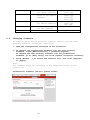
2.2. Web Interface Access
Open your web browser, and enter 192.168.11.1 into the address bar.
The status page will be displayed.
A screen for entering the username and password is displayed. Enter
the username and password to log in.
Note:
The default username is "admin", and the default password is
"password".
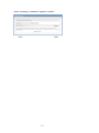
After logging in, the "Setup Assistant" screen is displayed. Follow
the on-screen instructions to complete the settings. For details on
the Internet initial settings using "Setup Assistant", see the Quick
Setup Guide provided with the product.
-4-
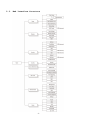
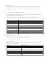
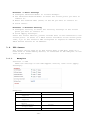
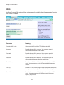
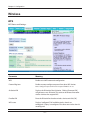
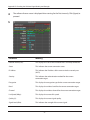
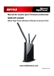
2.3. Web Interface Structure
-5-
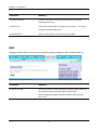
2.3.1.
Setup
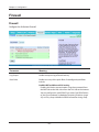
2.3.1.1.
Basic Configuration
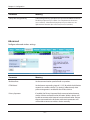
Setup Information
The SSID, wireless passphrase, IP address, username, and password that
were set for the AirStation are displayed.
Clicking [Run Initial Setup Wizard] opens the "Setup Assistant" screen.
Follow the on-screen instructions to make the initial settings for the
AirStation.
Clicking [Print Setup Card] will print out the information displayed
on this screen.
If multiple SSIDs for guests are set, clicking [Print Guest Card] will
print out the encryption key for each SSID that is set in the
AirStation.
The information (SSID, wireless passphrase, username, password)
displayed in the Setup Card Information area can be edited directly by
simply clicking the desired information. After making any changes, be
sure to click [Apply Changes] to apply the new settings to the
AirStation.
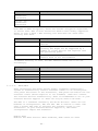
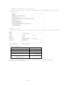
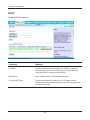
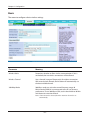
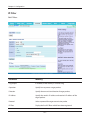
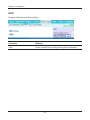
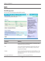
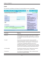
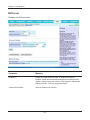
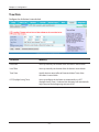
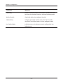
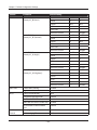
WAN Setup
Here you’ll find the most important settings to configure your
internet access and WAN port. DHCP is enabled by default, but you can
also use PPPoE, PPTP, L2TP, static IP, or HeartBeat Signal. If you
don’t use a password to log in to your ISP, you may need to enter
“0000” for the password. Also, for some ISPs you should not enter the
service name, as it will prevent establishing the connection. If you
experience connection problems, then leave the service name empty.
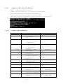
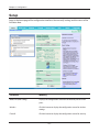
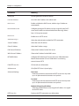
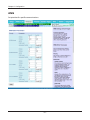
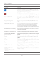
WAN Connection Type
Description
Disabled
The WAN port is disabled.
Static IP
A static IP address will be used – enter the
IP address, subnet mask, gateway, and server
manually.
Automatic
Configuration - DHCP
The router obtains its WAN-side IP address
from a DHCP server.
PPPoE
Configure as PPPoE-client.
PPTP
Establishes connection via PPTP.
L2TP
Establishes connection via L2TP.
HeartBeat Signal
If you use a HeartBeat connection, consult
your ISP for setup information. HeartBeat
Signal is used only in Australia.
3G/UMTS
Configures Internet Access via 3G/UMTS.
Enable USB in the “Services” section and
attach a 3g/UMTS USB stick to the router.
This setting is available in AirStations sold
in the European region only.
-6-
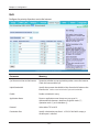
Network Setup
Network Setup configures the router’s basic settings to match the
local network. By default these settings are valid for all network
ports except the WAN because they are all attached to the default
bridge. If ports are disassociated from the bridge they will have
different settings.
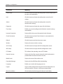
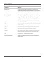
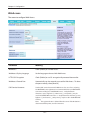
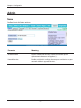
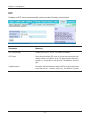
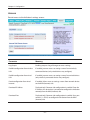
2.3.1.2.
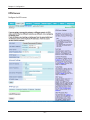
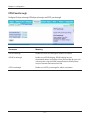
Dynamic DNS (DynDNS or DDNS)
Dynamic DNS allows the assignment of a DNS record to a dynamically
assigned WAN-side IP address. A DynDNS client updates DNS records when
your WAN-side IP address changes.
The router’s firmware offers presets for the most common DynDNS
services plus an option to define individual settings.
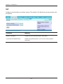
DynDNS Service
Description
Disabled
Default, no DynDNS
DynDNS.org
freedns.afraid.org
ZoneEdit.com
No-IP.com
3322.org
easyDNS.com
TZO.com
DynSIP.org
Custom
2.3.1.3.
Individual DynDNS service configuration
MAC Address Cloning
MAC address cloning lets you assign a different MAC address to the
router than the one encoded in the hardware.
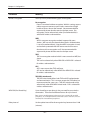
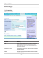
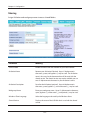
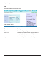
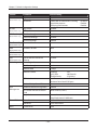
2.3.1.4.
Advanced Routing
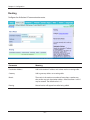
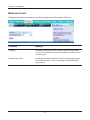
Operating Mode
The default operating mode of the router is Gateway. Other routing
protocols are available.
Modus
Description
Gateway
Gateway (default)
BGP
BGP Routing
Rip2 Router
Rip2 Routing
OSPF Router
OSPF Router
vtysh OSPF BGP RIP router
vtysh OSPF BGP RIP router
OLSR Router
OLSR Router
Router
Router
-7-
Static Routing
The Static Routing section lets you add static routes. The input
parameters are equivalent to the parameters of the Linux command
“route”.
2.3.1.5.
Networking
The Networking section allows detailed network configuration.
VLAN Tagging
Use this option to configure VLAN tagging.
Bridging
By default, one bridge (br0) is defined and active. In this section
you can define additional bridges and change the interface assignment
according to your requirements.
Bonding
Bonding offers the ability to “bond” interfaces together. Bonding can
be used to enhance throughput or provide failover capabilities.
Port Setup
The port setup section allows further configuration of the routers
network interfaces. Network interfaces can be separated from the
bridge and it is possible to assign separate network settings for each
interface. If an interface is separated from the bridge, add routing
rules to allow communication between the interface and the bridge or
other unbridged interfaces.
DHCPD
Besides the default DHCP server, you can define additional DHCP
servers.
2.3.1.6.
EoIP Tunnel (WZR series only)
EoIP (Ethernet over IP) tunnels can transport Ethernet data packages
via a tunnel over existing IP connections. You can define up to 10
tunnels that can also be bonded.
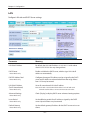
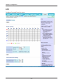
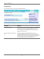
2.3.2.
Wireless
2.3.2.1.
Basic Settings
Each Wireless LAN interface has its own section in the wireless basic
settings screen. The wireless interfaces are labelled ath0 and ath0.1
– ath0.4 depending on the number of radios installed. To correctly
identify the antenna connectors, please compare the MAC addresses
printed on the enclosure with the addresses displayed in the web
interface.
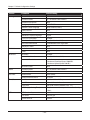
Wireless Mode
This parameter is used to define the operating mode of the Wireless
LAN interface. You can select among the following modes:
-8-
Modus
Description
AP
WLAN Access Point mode (default)
Client
WLAN Client mode
Client-Bridge
Client-Bridge mode allows connecting to
another Wireless LAN access point and
establishing a network bridge with that
access point
Adhoc
Adhoc operating mode, required for building
mesh networks
WDS Station
WDS Station is the client in a WDS-AP <-> WDS
station bridge. This is a special wireless
networking mode that offers better
flexibility and security than the classical
MAC address based WDS.
WDS AP
WDS AP is the AP side for WDS AP <-> WDS
Station. A WDS AP allows connections from WDS
Stations and Wireless Clients.
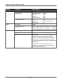
Wireless Network Mode
Defines the IEEE802.11 networking mode.
Mode
Description
Disabled
Interface is disabled
Mixed
2.4 GHz 802.11b / 802.11g / 802.11n mixed
mode
A-Only
5 GHz 802.11a mode (802.11b, 802.11g, and
802.11n devices cannot connect)
B-Only
2.4 GHz 802.11b mode (802.11a, 802.11g, and
802.11n devices cannot connect)
G-Only
2.4 GHz 802.11g mode (802.11a, 802.11b, and
802.11n devices cannot connect)
BG-Mixed
2.4 GHz 802.11b & 802.11g mixed mode (802.11a
and 802.11n devices cannot connect)
NA-Mixed
5 GHz 802.11n & 802.11a mixed mode (802.11b
and 802.11g devices cannot connect)
NG-Mixed
2.4 GHz 802.11n & 802.11g mixed mode (802.11a
and 802.11b devices cannot connect)
N-Only (5 GHz)
5 GHZ 802.11n mode (802.11a, 802.11b, and
802.11g devices cannot connect)
N-Only (2.4 GHz)
2.4 GHZ 802.11n mode (802.11a, 802.11b, and
802.11g devices cannot connect)
Channel Width
Some wireless network modes support wireless channel widths besides
the standard 20 MHz. 802.11g & 802.11n offer the option to use 40 MHz
channels for enhanced throughput. Both the AP and the client must
support 40 MHz channels to use them.
-9-
Wireless Channel (AP only)
Set the desired wireless channel, or let the router choose a free
channel automatically. If the router is in classic WDS (MAC address
based) mode, then the wireless channel must be selected manually.
Wireless Network Name (SSID)
The name of the wireless network the radio transmits or connects to
(depending on the wireless mode)
Wireless SSID Broadcast (AP only)
The name of the wireless network (SSID) may be broadcasted or not. Not
broadcasting does not prevent the network from being detected by a
wireless network sniffer; it just hides the name.
Advanced Settings
Check this box to get access to advanced wireless settings. These
advanced parameters should be only modified by experienced users.
2.3.2.2.
Wireless Security
Because wireless data packets can easily be sniffed, wireless
connections require a greater level of security to ensure that data
cannot be read by unauthorized users.
Security Mode
Mode
Description
Disabled
No encryption set (not recommended!)
WPA-PSK
WPA encryption with a passphrase (text
password)
WPA-EAP (AP only)
WPA encryption with Radius Client
authentication according to 802.1x
WPA2-PSK
WPA2 encryption with a passphrase (text
password)
WPA2-EAP (AP only)
WPA2 encryption with Radius Client
authentication according to 802.1x
WPA2-PSK / WPA-PSK
WPA & WPA2 encryption in WPA/WPA2 mixed mode
with a passphrase (text password)
WPA2-EAP / WPA-EAP
(AP only)
WPA & WPA2 encryption in WPA/WPA2 mixed with
Radius Client authentication according to
802.1x
RADIUS
No encryption set with Radius Client
authentication (insecure; not recommended)
Not supported.
WEP
WEP 64 Bit / 128 Bit encryption (insecure;
not recommended!)
When using WEP encryption (not recommended), the user can choose
between 64 bit and 128 bit keys. Keys can be entered as passphrases
that are used to generate the Hex keys. Theoretically 128 bit keys
offer a higher level of security but because of design flaws, that’s
not the case in actual use.
- 10 -
Key length
Description
64 Bit (10
Hexadecimal
characters)
Standard
128 Bit (26
Hexadecimal
characters)
With WPA or WPA2 encryption, there are several encryption algorithms
to choose from. AES is more secure but TKIP is more widely supported.
There is also a TKIP + AES setting, but that does not offer more
security than TKIP.
Algorithm
Description
TKIP
TKIP encryption, supported by most clients
devices
AES
AES encryption offers a better level of
security but might not be supported by a
number of client devices and requires less
CPU processing power.
TKIP + AES
Mixed mode – offers best compatibility but
doesn’t work in all environments
If RADIUS security is used, the MAC address format has to be set
accordingly.
RADIUS MAC format
options
Description
aabbcc-ddeeff
Standard
aabbccddeeff
aa:bb:cc:dd:ee:ff
aa-bb-cc-dd-ee-ff
2.3.2.3.
AOSS/WPS
AOSS (AirStation One-touch Secure Setup) is Buffalo Technology’s
system to automatically connect wireless clients to an access point.
Just press the button on the AirStation, then press the button for the
wireless client (which might be in its software). AOSS will connect
the wireless devices automatically. AOSS is recommended if all of your
wireless devices support it. AOSS can only be used in AP mode.
The WPS is a standard created by the Wi-Fi Alliance. There are two
methods of configuration, PBC and PIN. PBC is similar to AOSS. PIN
uses a unique PIN code to register the wireless client to the
AirStation. If your wireless devices support it, WPS makes
configuration simple and automatic.
Enable AOSS
Enables the AOSS Service. When disabled, AOSS cannot be used.
- 11 -
Start AOSS Negotiation
To initiate AOSS, either click the AOSS button in the GUI or hold down
the AOSS button on the front of the router for 3 seconds.
Security Modes
You may choose which security modes are offered in the AOSS
negotiation process. The use of WEP in general is not recommended due
to security concerns.
WPS Button
Enables the WPS button. When disabled, WPS button cannot be used.
WPS PIN
Enter the PIN code printed on your client device or your client
authentication application.
2.3.2.4.
MAC Filter
The MAC Filter defines a list of client MAC addresses that are allowed
to connect wirelessly. MAC addresses that aren’t on the list aren’t
allowed to connect.
2.3.2.5.
WDS
Wireless Distribution System (WDS) is a special access point mode that
allows the connection of several access points to form a combined
network. Such a network can be used to extend wireless network
coverage.
The MAC addresses of the access points nearest to the current access
point are entered as WDS nodes. Avoid creating “double” connections,
i.e. A <-> B + A <-> B <-> C. These modes are available to connect WDS
nodes:
WDS Client Mode
Description
disabled
Standard
Point-to-Point
Commonly used mode
LAN
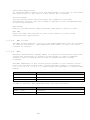
If WDS is enabled, then WDS NAT modes are also available.
WDS NAT Mode
Description
WLAN -> WDS
Standard
WDS -> WLAN
- 12 -
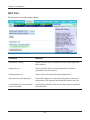
2.3.3.
Services
2.3.3.1.
Services
The services section allows the configuration of basic service
settings. Telnet and SSH can be configured this way. Remote access
options are configured in the Administration section.
Available DHCP Server
Domains
Description
WAN
Standard
LAN / WLAN
Rflow / MACupd
Interface Options
Description
LAN & WLAN
Standard
LAN
WLAN
2.3.3.2.
FreeRadius (WZR series only)
Certain applications (for example, Chillispot hotspot software)
benefit from a RADIUS server for management of user credentials and
settings.
Server Certificate
This section contains the parameters to generate the RADIUS server
certificate. The certificate needs to be generated before clients can
be configured to connect to the RADIUS server.
Certificate Status
Displays the server certificate creation status.
Settings
Choose the port that the RADIUS server uses for client communication.
The default port is 1812.
Clients
This section is used to define RADIUS clients (required for HotSpot
usage).
Users
Lists the users defined in the RADIUS servers.
modification of accounts.
2.3.3.3.
Allows creation and
PPPoE Server
Some applications require a PPPoE server on the router, which can be
configured here. The PPPoE server is disabled by default.
2.3.3.4.
VPN
The router can also be configured as VPN server or VPN client.
- 13 -
PPTP
When defining the PPTP server’s IP range, avoid overlap with the range
of IP addresses handed out by DHCP if DHCP is enabled. The IP range is
defined using the following syntax:
xxx.xxx.xxx.<start-ip>-<end-ip>
for example
192.168.1.20-30
Enter client login data follows:
<username> * <password> *
for example
testuser * test *
The encryption options can be set as follows
PPTP server type
Settings
DD-WRT Router
mppe required (Standard)
Windows PPTP Server
mppe required,no40,no56,stateless or
mppe required,no40,no56,stateful
OpenVPN
OpenVPN is a powerful and flexible VPN solution. OpenVPN security is
based on certificates that cannot created on the router itself. Please
refer to OpenVPN’s online documentation for instructions on creating
certificates and configuring OpenVPN.
2.3.3.5.
USB (WZR series only)
The router’s USB port can be used for several purposes. Here the basic
and advanced USB parameters are defined. Besides enabling USB and
defining the USB hardware standard to use you can also define if
printer and storage support for USB shall be enabled.
2.3.3.6.
NAS (WZR series only)
If USB hard drive support is enabled, you can start the integrated
ProFTPd server to share data on an attached hard disk via FTP.
The User/Password data are entered as follows:
<username> * <password> *
for example
testuser * test *
- 14 -
Be careful enabling anonymous login. If anonymous login is enabled,
everyone accessing your network has permission to read and write data.
2.3.3.7.
Hotspot
Most hotspot software requires a server to store user settings and
login information. Please note that Sputnik is a commercial hotspot
service that requires an agreement with Sputnik for usage.
2.3.3.8.
SIP Proxy (WZR series only)
This package is an implementation of the Milkfish SIP router.
2.3.3.9.
My Ad Network
Allows the creation of an AnchorFree Hotspot that can be used to
create revenue via AnchorFree.
2.3.4.
Security
2.3.4.1.
Firewall
Aside from enabling and disabling the firewall, you can also set
additional filters, block certain network requests for the WAN
interface, and manage logs.
2.3.4.2.
VPN Pass-through
VPN settings effect how the firewall handles IPSec, PPTP, and L2TP
connections. By default, pass-through is enabled. Please note that
disabling pass-through will usually prevent you from establishing VPN
connections from computers located in your local network to VPN
servers on the internet.
2.3.5.
Access Restrictions
2.3.5.1.
WAN Access
The WAN access settings allow the definition of time and service
related access rules.
2.3.6.
NAT / QoS
2.3.6.1.
Port Forwarding
Port forwarding allows the assigning of WAN ports to specific internal
IP addresses and matching ports. Bidirectional external traffic can be
forwarded to specific internal devices and computers. Each port
forwarding entry defines a source port and a target IP address.
Before adding or removing a port forwarding entry, save all changed
settings. Any changes not saved will be lost when a port forwarding
entry is added or deleted.
- 15 -
2.3.6.2.
Port Range Forwarding
Port range forwarding works similarly to port forwarding. Unlike port
forwarding, instead of a single port, a range of ports is forwarded to
the same range of ports at the internal target IP address.
2.3.6.3.
Port Triggering
Port triggering is a kind of port range forwarding where outgoing
traffic on specific ports enables previously defined port forwards for
the activating device. This temporarily opens required ports when
specific applications are opened on computers on the LAN. This offers
a greater level of security than port forwarding or port range
forwarding because the ports are only opened when needed.
2.3.6.4.
UPnP
UPnP allows UPnP capable applications and devices to open and close
required ports automatically as needed. This is simple to use and does
not require further configuration steps.
2.3.6.5.
DMZ
A DMZ computer is a special computer in the internal network that gets
all incoming traffic forwarded. The task of that computer is managing
this traffic. When the DMZ feature is activated the internal firewall
is activated. This can pose a security issue if not handled with care.
Furthermore, several services of the router, that have to be
accessible from the WAN side, will not work because the associated
traffic is forwarded to the DMZ computer.
2.3.6.6.
QoS
QoS (Quality of Service) is a procedure to prioritise network traffic
by application. Specific services can be assigned specific bandwidth.
Aside from upstream and downstream bandwidth, you can define settings
for specific services and IP and MAC address ranges.
2.3.7.
Administration
2.3.7.1.
Management
The Management section contains settings for remotely accessing the
router and other basic settings that are usually not changed. The
settings for the language used in the Web GUI are also located here.
You may choose between Chinese (simplified & traditional), Croatian,
Dutch, French, German, Hungarian, Italian, Japanese, Latvian, Polish,
Portuguese, Romanian, Russian, Slovenian, Spanish, and Swedish. The
default setting is English.
Before using Telnet or SSH, activate the associated service(s) in this
section.
- 16 -
2.3.7.2.
Keep Alive
Keep-Alive lets you configure monitoring options that automatically
reboot the router if a service malfunction causes it to fail to
respond.
2.3.7.3.
Commands
Entering Linux commands is one of the most powerful ways to access the
router’s functionality. This enables you to access services and
configure options that are not accessible via the Web GUI. Using shell
commands can lead to unexpected results. Use them with utmost care.
Aside from executing the shell commands directly you can also save
custom start up and firewall scripts.
2.3.7.4.
WOL
With Wake-on-LAN, you can send special data packets to compatible
devices on your LAN, causing them to exit sleep mode.
WOL data packets can be triggered manually or scheduled automatically.
2.3.7.5.
Factory Defaults
With this feature you can reset the router’s settings to factory
defaults. After a reset, the router will restart.
2.3.7.6.
Firmware Upgrade
The firmware upgrade option can be used to install a different
firmware version. When doing this you can choose if the router’s
settings will be restored to factory defaults or kept.
2.3.7.7.
Backup
You can use this feature to store your current configuration into a
backup file, or to restore from a previously stored configuration.
This also makes it simple to set up a number of routers with the exact
same configuration.
2.3.8.
Status
2.3.8.1.
Router
The status screen displays information about the router, such as cpu
load, memory consumption, and currently active IP connections. Status
is updated automatically.
2.3.8.2.
WAN
If the WAN interface is enabled, this screen displays WAN settings and
throughput statistics.
- 17 -
2.3.8.3.
LAN
Here you can find LAN-related information like active clients and DHCP
clients.
2.3.8.4.
Wireless
The wireless LAN status screen displays the current wireless LAN
interface configuration, wireless LAN clients (in AP modes), and
access points (in client modes). If there’s more than one wireless LAN
interface, you can switch between them via the interface pull down
menu.
2.3.8.5.
Bandwidth
Bandwidth monitoring displays real time diagrams for incoming and
outgoing traffic for each network interface.
2.3.8.6.
SysInfo
The SysInfo screen combines the most important information of the
other status pages. By default, the SysInfo page can be accessed from
LAN devices without authentication. That can be changed in the
Management section of the Administration area.
- 18 -
3.
Use Cases
The following use cases relate to the most commonly used router
configurations. The related router configuration is explained step by
step.
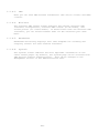
3.1. Access Point
Access Point (AP, sometimes also called “Infrastructure Mode”) is the
mode where the router is also the central wireless hub that connects
to the LAN and provides access to wireless devices. These wireless
clients of the AP can communicate with each other and with wired
devices on the network such as the Internet.
Connect your computer to the router as described in 2.1. and access
the web interface according to 2.2.
3.1.1.
Access Point with NAT / DHCP
Setup -> Basic Setup
WAN Setup
o In ”Connection Type”, choose the type of WAN connection you want
to use and complete the related settings.
Network Setup
o Enter the desired LAN IP address for the router into “Router IP“.
o Set “DHCP Type“ to “DHCP Server“ (this is the default).
o “Enable“ DHCP Server (this is the default).
o Adjust the DHCP address range to match your requirements.
Time Settings
o Choose your time zone.
Click “Save“.
Wireless -> Basic Settings
- 19 -
Configure “Wireless Mode“ to “AP“
Set your desired wireless mode in “Wireless Network Mode“. Please
note that mixed modes will lead to reduced performance because of
maintaining compatibility.
Enter a name for your wireless network into “Wireless Network Name
(SSID)”
Click “Save“
Wireless -> Wireless Security
Choose and configure a security mode. Please note that WEP is
insecure and should only be used if no other option is available.
Click “Apply Settings“
You can now connect the router to the Internet and your local network.
After you successfully connect wireless devices, they will then be
displayed on the “SysInfo” and “WLAN Status” pages.
3.1.1.
Access Point attached to a network / Internet gateway
Setup -> Basic Setup
WAN Setup
o For “Connection Type“, choose “Disabled”.
Network Setup
o Enter the desired LAN-side IP address for the router into “Router
IP“.
o Set the “DHCP Type“ to “DHCP Server“ (this is the default).
o “Disable” “DHCP Server“.
Time Settings
o Choose your time zone.
Click “Save“.
Wireless -> Basic Settings
Configure “Wireless Mode“ to “AP“
Choose a wireless mode in “Wireless Network Mode“. Please note that
mixed modes will lead to reduced performance because of maintaining
compatibility.
Enter a name for your wireless network into “Wireless Network Name
(SSID)”.
Click “Save“.
Wireless -> Wireless Security
Choose and configure your desired security mode. Please note that
WEP is insecure and should only be used if no other option is
available.
Click “Apply Settings“
You can now connect the router to the Internet and your local network.
If you’re running a DHCP server in your LAN, connected wireless
devices will get their IP addresses from the server.
- 20 -
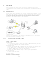
3.2. Wireless Client
The router can be also used as a wireless LAN client. This can be
useful if you want to connect devices to your wireless LAN that do not
have a wireless LAN interface. In this configuration, the wireless LAN
interface acts as a wireless client. Attached wired Ethernet devices
can also access the WAN through the wireless connection.
Setup -> Basic Setup
WAN Setup
o Set “Connection Type“ to “DHCP” to have the AirStation get its IP
address from a DHCP server, or to a “Static IP“ if no DHCP server
is available.
Network Setup
o Enter the desired LAN-side IP address for the router in “Router
IP“.
o Set the “DHCP Type“ to “DHCP Server“ (this is the default setting).
o “Enable” “DHCP Server“ (this is the default setting).
o Adjust the DHCP address range to match your requirements.
Time Settings
o Choose your time zone.
Click “Save“.
Wireless -> Basic Settings
Configure “Wireless Mode“ to “Client“.
Configure “Wireless Network Mode” to match the capabilities of the
access point you want to connect to.
Enter the network name (SSID) of the AP you want to connect to into
“Wireless Network Name (SSID)”.
Click “Save“.
- 21 -
Wireless -> Wireless Security
Configure the security mode to match the security settings of the
access point you want to connect to.
Click “Apply Settings“.
After the router reboots, please confirm that it has connected to the
access point. If there is a DHCP server available on the access point
side, and the router is configured to request an IP address, then it
should receive an IP address for its WAN-side interface.
You can now either connect wired clients to the access point or
configure another wireless network interface as an access point to
grant access to wireless clients.
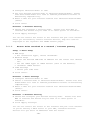
3.3. Wireless Client Bridge
A wireless client bridge offers the ability to transparently integrate
the router’s LAN into a different LAN that another access point is
connected to. Clients connected to such a router can access devices in
both LANs and vice versa. In that configuration the router’s WAN
interface is disabled.
Setup -> Basic Setup
WAN Setup
o Choose “Disabled” for “Connection Type” (this will be set
automatically).
Network Setup
o Enter the desired LAN-side IP address for the router into “Router
IP”.
o “Disable“ “DHCP Server”.
Time Settings
o Choose your time zone.
Click “Save”.
- 22 -
Wireless -> Basic Settings
Configure “Wireless Mode” to “Client Bridge”.
Set “Wireless Network Mode” to match the access point you want to
connect to.
Enter the network name (SSID) of the AP you want to connect to.
Click “Save”.
Wireless -> Wireless Security
Configure security to match the security settings of the access
point you want to connect to.
Click “Apply Settings”.
After the router reboots, please confirm that it has connected to the
access point. If there is a DHCP server available on the access point
side, a pc in the router’s LAN configured to request an address from
DHCP should receive an IP address.
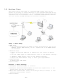
3.4. FTP Server
The router can be used as an FTP server when a USB disk (such as a
hard disk or flash memory device) is connected to the USB port on the
rear of the router.
3.4.1.
Examples
Services -> USB
・Make the settings in the USB Support section, then click [Apply
Settings].
Examples:
Core USB Support
USB Printer
Support
USB Storage
Support
Automatic Drive
Mount
Run-on-mount
Script Name
Disk Mount Point
- 23 -
Enabled
Disabled
Enabled
Enabled
blank
/mnt
・Connect a USB disk to the router.
After a short wait, the disk information is displayed in the Disk
Info section.
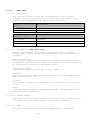
Services -> NAS
・Make the settings in the ProFTPD section, and click [Apply Settings].
Setting example:
ProFTPD
Server Port
Files Directory
Allow Write
User Password List
Anonymous Login
(Read-only)
Enable
21
/mnt
Enable
buffalo
12345678
Disable
Separate the username (example: buffalo) and password (example:
12345678) with a space.
- 24 -
3.4.2.
Logging into the FTP server
・Open a command prompt window.
・Enter “ftp 192.168.11.1” to access the FTP server.
・Enter the user name, and press the Enter key.
・Enter the password, and press the Enter key.
・When the login is successful, “ftp>” appears on the screen.
・To logout, enter the “bye” command.
3.4.3.
Common FTP commands
Command
ftp
ls
pwd
cd
mkdir
rmdir
lcd
asc
bin
put
mput
get
mget
Description
Starts FTP
Displays a list of
the remote
directory’s files
Displays the
current directory
on the remote
computer
Changes the current
working directory
on the remote
computer
Creates a remote
directory
Deletes a remote
directory
Changes the current
working directory
on the local
computer
Switches to ASCII
transfer mode
Switches to binary
transfer mode
Uploads a file to
the remote computer
Uploads multiple
files to the remote
computer
Downloads a file to
the local computer
Downloads multiple
files to the local
computer
- 25 -
Entry example
ftp
ls
pwd
cd img
mkdir test
rmdir test
lcd E:\test
asc
bin
put test.pdf
mput test1.jpg
test2.jpg
test3.jpg
get index.html
mget test1.jpg
test2.jpg
test3.jpg
delete
mdelete
Deletes a file on
the remote computer
Deletes multiple
files on the remote
computer
rename
Renames a file on
the remote computer
help
Displays the Help
for FTP commands
Exits FTP
bye
delete
test1.jpg
mdelete
test1.jpg
test2.jpg
test3.jpg
rename
test1.jpg
new1.jpg
help
bye
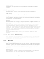
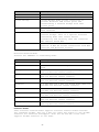
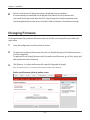
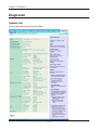
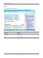
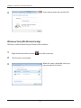
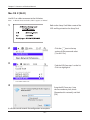
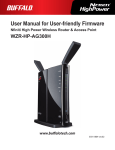
3.5. Changing Firmware
To change between the professional firmware (dd-wrt) and the userfriendly firmware, follow the steps below.
1. Open the configuration Interface of the AirStation.
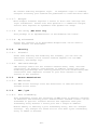
2. To replace the professional firmware with the user-friendly
firmware, click [Administration] > [Firmware Upgrade].
To replace the user-friendly firmware with the professional
firmware, go to [Easy Setup] and click [Update AirStation Firmware].
3. Click [Browse...] to select the firmware file, and click [Upgrade]
or [Apply].
Note:
The firmware files are contained in the “Firmware” folder of the
utility CD.
Professional firmware (dd-wrt) update screen:
- 26 -
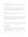
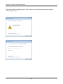
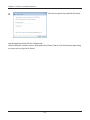
User-friendly firmware update screen:
- 27 -
4.
GPL Statement
The firmware that is used in this product includes software that is
subject to the GNU Public Licence (GPL)/the GNU Lesser Public Licence
(LGPL). To the extent that it is applicable within the context of the
GPL and the LGPL, the conditions of the GPL and the LGPL, as well as
the relevant source codes, are available from the manufacturer. The
code underlying the GPL/LGPL for the software shall be provided,
without any ensuing warranty or liability claims. Please see the
conditions of the GPL/LGPL for further details.
4.1. GNU General Public License
Version 2, June 1991
Copyright (C) 1989, 1991 Free Software Foundation, Inc. 51 Franklin
Street, Fifth Floor, Boston, MA 02110-1301, USA
Everyone is permitted to copy and distribute verbatim copies of this
license document, but changing it is not allowed.
4.1.1.
Preamble
The licenses for most software are designed to take away your freedom
to share and change it. By contrast, the GNU General Public License
is intended to guarantee your freedom to share and change free
software--to make sure the software is free for all its users. This
General Public License applies to most of the Free Software
Foundation's software and to any other program whose authors commit to
using it. (Some other Free Software Foundation software is covered by
the GNU Library General Public License instead.) You can apply it to
your programs, too.
When we speak of free software, we are referring to freedom, not price.
Our General Public Licenses are designed to make sure that you have
the freedom to distribute copies of free software (and charge for this
service if you wish), that you receive source code or can get it if
you want it, that you can change the software or use pieces of it in
new free programs; and that you know you can do these things.
To protect your rights, we need to make restrictions that forbid
anyone to deny you these rights or to ask you to surrender the rights.
These restrictions translate to certain responsibilities for you if
you distribute copies of the software, or if you modify it.
For example, if you distribute copies of such a program, whether
gratis or for a fee, you must give the recipients all the rights that
you have. You must make sure that they, too, receive or can get the
source code. And you must show them these terms so they know their
rights.
We protect your rights with two steps: (1) copyright the software, and
(2) offer you this license which gives you legal permission to copy,
distribute and/or modify the software.
Also, for each author's protection and ours, we want to make certain
that everyone understands that there is no warranty for this free
- 28 -
software. If the software is modified by someone else and passed on,
we want its recipients to know that what they have is not the original,
so that any problems introduced by others will not reflect on the
original authors' reputations.
Finally, any free program is threatened constantly by software patents.
We wish to avoid the danger that redistributors of a free program will
individually obtain patent licenses, in effect making the program
proprietary. To prevent this, we have made it clear that any patent
must be licensed for everyone's free use or not licensed at all.
The precise terms and conditions for copying, distribution and
modification follow.
4.1.2.
GNU General Public License – Terms and Conditions or Copying,
Distribution and Modification
0. This License applies to any program or other work which contains a
notice placed by the copyright holder saying it may be distributed
under the terms of this General Public License. The "Program", below,
refers to any such program or work, and a "work based on the Program"
means either the Program or any derivative work under copyright law:
that is to say, a work containing the Program or a portion of it,
either verbatim or with modifications and/or translated into another
language. (Hereinafter, translation is included without limitation in
the term "modification".) Each licensee is addressed as "you".
Activities other than copying, distribution and modification are not
covered by this License; they are outside its scope. The act of
running the Program is not restricted, and the output from the Program
is covered only if its contents constitute a work based on the Program
(independent of having been made by running the Program). Whether that
is true depends on what the Program does.
1. You may copy and distribute verbatim copies of the Program's source
code as you receive it, in any medium, provided that you conspicuously
and appropriately publish on each copy an appropriate copyright notice
and disclaimer of warranty; keep intact all the notices that refer to
this License and to the absence of any warranty; and give any other
recipients of the Program a copy of this License along with the
Program.
You may charge a fee for the physical act of transferring a copy, and
you may at your option offer warranty protection in exchange for a fee.
2. You may modify your copy or copies of the Program or any portion of
it, thus forming a work based on the Program, and copy and distribute
such modifications or work under the terms of Section 1 above,
provided that you also meet all of these conditions:
a) You must cause the modified files to carry prominent notices
stating that you changed the files and the date of any change.
b) You must cause any work that you distribute or publish, that in
whole or in part contains or is derived from the Program or any part
- 29 -
thereof, to be licensed as a whole at no charge to all third parties
under the terms of this License.
c) If the modified program normally reads commands interactively when
run, you must cause it, when started running for such interactive use
in the most ordinary way, to print or display an announcement
including an appropriate copyright notice and a notice that there is
no warranty (or else, saying that you provide a warranty) and that
users may redistribute the program under these conditions, and telling
the user how to view a copy of this License. (Exception: if the
Program itself is interactive but does not normally print such an
announcement, your work based on the Program is not required to print
an announcement.)
These requirements apply to the modified work as a whole. If
identifiable sections of that work are not derived from the Program,
and can be reasonably considered independent and separate works in
themselves, then this License, and its terms, do not apply to those
sections when you distribute them as separate works. But when you
distribute the same sections as part of a whole which is a work based
on the Program, the distribution of the whole must be on the terms of
this License, whose permissions for other licensees extend to the
entire whole, and thus to each and every part regardless of who wrote
it.
Thus, it is not the intent of this section to claim rights or contest
your rights to work written entirely by you; rather, the intent is to
exercise the right to control the distribution of derivative or
collective works based on the Program.
In addition, mere aggregation of another work not based on the Program
with the Program (or with a work based on the Program) on a volume of
a storage or distribution medium does not bring the other work under
the scope of this License.
3. You may copy and distribute the Program (or a work based on it,
under Section 2) in object code or executable form under the terms of
Sections 1 and 2 above provided that you also do one of the following:
a) Accompany it with the complete corresponding machine-readable
source code, which must be distributed under the terms of Sections 1
and 2 above on a medium customarily used for software interchange; or,
b) Accompany it with a written offer, valid for at least three years,
to give any third party, for a charge no more than your cost of
physically performing source distribution, a complete machine-readable
copy of the corresponding source code, to be distributed under the
terms of Sections 1 and 2 above on a medium customarily used for
software interchange; or,
c) Accompany it with the information you received as to the offer to
distribute corresponding source code. (This alternative is allowed
only for non-commercial distribution and only if you received the
program in object code or executable form with such an offer, in
accord with Subsection b above.)
- 30 -
The source code for a work means the preferred form of the work for
making modifications to it. For an executable work, complete source
code means all the source code for all modules it contains, plus any
associated interface definition files, plus the scripts used to
control compilation and installation of the executable. However, as a
special exception, the source code distributed need not include
anything that is normally distributed (in either source or binary
form) with the major components (compiler, kernel, and so on) of the
operating system on which the executable runs, unless that component
itself accompanies the executable.
If distribution of executable or object code is made by offering
access to copy from a designated place, then offering equivalent
access to copy the source code from the same place counts as
distribution of the source code, even though third parties are not
compelled to copy the source along with the object code.
4. You may not copy, modify, sublicense, or distribute the Program
except as expressly provided under this License. Any attempt
otherwise to copy, modify, sublicense or distribute the Program is
void, and will automatically terminate your rights under this License.
However, parties who have received copies, or rights, from you under
this License will not have their licenses terminated so long as such
parties remain in full compliance.
5. You are not required to accept this License, since you have not
signed it. However, nothing else grants you permission to modify or
distribute the Program or its derivative works. These actions are
prohibited by law if you do not accept this License. Therefore, by
modifying or distributing the Program (or any work based on the
Program), you indicate your acceptance of this License to do so, and
all its terms and conditions for copying, distributing or modifying
the Program or works based on it.
6. Each time you redistribute the Program (or any work based on the
Program), the recipient automatically receives a license from the
original licensor to copy, distribute or modify the Program subject to
these terms and conditions. You may not impose any further
restrictions on the recipients' exercise of the rights granted herein.
You are not responsible for enforcing compliance by third parties to
this License.
7. If, as a consequence of a court judgment or allegation of patent
infringement or for any other reason (not limited to patent issues),
conditions are imposed on you (whether by court order, agreement or
otherwise) that contradict the conditions of this License, they do not
excuse you from the conditions of this License. If you cannot
distribute so as to satisfy simultaneously your obligations under this
License and any other pertinent obligations, then as a consequence you
may not distribute the Program at all. For example, if a patent
license would not permit royalty-free redistribution of the Program by
all those who receive copies directly or indirectly through you, then
the only way you could satisfy both it and this License would be to
refrain entirely from distribution of the Program.
If any portion of this section is held invalid or unenforceable under
any particular circumstance, the balance of the section is intended to
- 31 -
apply and the section as a whole is intended to apply in other
circumstances.
It is not the purpose of this section to induce you to infringe any
patents or other property right claims or to contest validity of any
such claims; this section has the sole purpose of protecting the
integrity of the free software distribution system, which is
implemented by public license practices. Many people have made
generous contributions to the wide range of software distributed
through that system in reliance on consistent application of that
system; it is up to the author/donor to decide if he or she is willing
to distribute software through any other system and a licensee cannot
impose that choice.
This section is intended to make thoroughly clear what is believed to
be a consequence of the rest of this License.
8. If the distribution and/or use of the Program is restricted in
certain countries either by patents or by copyrighted interfaces, the
original copyright holder who places the Program under this License
may add an explicit geographical distribution limitation excluding
those countries, so that distribution is permitted only in or among
countries not thus excluded. In such case, this License incorporates
the limitation as if written in the body of this License.
9. The Free Software Foundation may publish revised and/or new
versions of the General Public License from time to time. Such new
versions will be similar in spirit to the present version, but may
differ in detail to address new problems or concerns.
Each version is given a distinguishing version number. If the Program
specifies a version number of this License which applies to it and
"any later version", you have the option of following the terms and
conditions either of that version or of any later version published by
the Free Software Foundation. If the Program does not specify a
version number of this License, you may choose any version ever
published by the Free Software Foundation.
10. If you wish to incorporate parts of the Program into other free
programs whose distribution conditions are different, write to the
author to ask for permission. For software which is copyrighted by
the Free Software Foundation, write to the Free Software Foundation;
we sometimes make exceptions for this. Our decision will be guided by
the two goals of preserving the free status of all derivatives of our
free software and of promoting the sharing and reuse of software
generally.
4.1.3.
NO WARRANTY
11. BECAUSE THE PROGRAM IS LICENSED FREE OF CHARGE, THERE IS NO
WARRANTY FOR THE PROGRAM, TO THE EXTENT PERMITTED BY APPLICABLE LAW.
EXCEPT WHEN OTHERWISE STATED IN WRITING THE COPYRIGHT HOLDERS AND/OR
OTHER PARTIES PROVIDE THE PROGRAM "AS IS" WITHOUT WARRANTY OF ANY KIND,
EITHER EXPRESSED OR IMPLIED, INCLUDING, BUT NOT LIMITED TO, THE
IMPLIED WARRANTIES OF MERCHANTABILITY AND FITNESS FOR A PARTICULAR
- 32 -
PURPOSE. THE ENTIRE RISK AS TO THE QUALITY AND PERFORMANCE OF THE
PROGRAM IS WITH YOU. SHOULD THE PROGRAM PROVE DEFECTIVE, YOU ASSUME
THE COST OF ALL NECESSARY SERVICING, REPAIR OR CORRECTION.
12. IN NO EVENT UNLESS REQUIRED BY APPLICABLE LAW OR AGREED TO IN
WRITING WILL ANY COPYRIGHT HOLDER, OR ANY OTHER PARTY WHO MAY MODIFY
AND/OR REDISTRIBUTE THE PROGRAM AS PERMITTED ABOVE, BE LIABLE TO YOU
FOR DAMAGES, INCLUDING ANY GENERAL, SPECIAL, INCIDENTAL OR
CONSEQUENTIAL DAMAGES ARISING OUT OF THE USE OR INABILITY TO USE THE
PROGRAM (INCLUDING BUT NOT LIMITED TO LOSS OF DATA OR DATA BEING
RENDERED INACCURATE OR LOSSES SUSTAINED BY YOU OR THIRD PARTIES OR A
FAILURE OF THE PROGRAM TO OPERATE WITH ANY OTHER PROGRAMS), EVEN IF
SUCH HOLDER OR OTHER PARTY HAS BEEN ADVISED OF THE POSSIBILITY OF SUCH
DAMAGES.
- 33 -
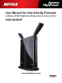
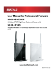
User Manual for User-friendly Firmware
AirStation NFINITI HighPower Wireless Router & Access Point
WZR-600DHP
www.buffalotech.com
Contents
Chapter 1 - Product Overview.......................................... 5
Professional or User-friendly?....................................................5
Package Contents......................................................................5
Hardware Overview...................................................................6
Front Panel LEDs............................................................................ 6
Back Panel...................................................................................... 8
Bottom............................................................................................. 9
Chapter 2 - Placing Your AirStation................................. 10
Vertical Placement.....................................................................10
Horizontal Placement.................................................................10
Wall Mounting............................................................................11
Chapter 3 - Installation......................................................12
Initial Setup................................................................................12
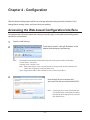
Chapter 4 - Configuration................................................. 16
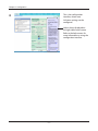
Accessing the Web-based Configuration Interface....................16
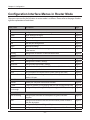
Configuration Interface Menus in Router Mode.........................18
Configuration Interface Menus in Bridge Mode..........................20
Setup..........................................................................................22
WAN/LAN...................................................................................24
Internet............................................................................................ 24
PPPoE............................................................................................ 25
DDNS.............................................................................................. 28
VPN Server..................................................................................... 30
LAN................................................................................................. 32
-1-
DHCP.............................................................................................. 34
NAT................................................................................................. 35
Routing............................................................................................ 36
Wireless.....................................................................................37
WPS................................................................................................ 37
Basic............................................................................................... 38
Advanced........................................................................................ 41
WMM............................................................................................... 42
MAC Filter....................................................................................... 44
AOSS.............................................................................................. 45
Multicast Control............................................................................. 47
Firewall.......................................................................................48
Firewall............................................................................................ 48
IP Filter............................................................................................ 50
VPN Passthrough........................................................................... 51
Games/Apps..............................................................................52
Port Forwarding.............................................................................. 52
DMZ................................................................................................ 53
UPnP............................................................................................... 54
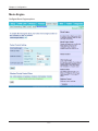
QoS................................................................................................. 55
Movie Engine.................................................................................. 57
NAS............................................................................................59
Disk Management........................................................................... 59
Shared Folder................................................................................. 61
Users............................................................................................... 63
Sharing............................................................................................ 64
WebAccess..................................................................................... 65
Media Server................................................................................... 67
BitTorrent......................................................................................... 68
Admin.........................................................................................70
Name.............................................................................................. 70
Password........................................................................................ 71
Time/Date....................................................................................... 72
-2-
NTP................................................................................................. 73
ECO................................................................................................ 74
Access............................................................................................ 76
Log.................................................................................................. 77
Save/Restore.................................................................................. 78
Initialize/Restart.............................................................................. 79
Update............................................................................................ 80
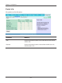
Diagnostic..................................................................................81
System Info..................................................................................... 81
Logs................................................................................................ 83
Packet Info...................................................................................... 84
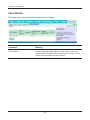
Client Monitor.................................................................................. 85
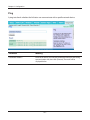
Ping................................................................................................. 86
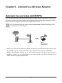
Chapter 5 - Connect to a Wireless Network.................... 87
Automatic Secure Setup (AOSS/WPS)......................................87
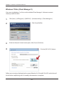
Windows 7/Vista (Client Manager V).............................................. 88
Windows XP (Client Manager 3)..................................................... 89
Mac OS X (AOSS Assistant)........................................................... 90
Other Devices (e.g. Game Console)............................................... 91
Manual Setup.............................................................................91
Windows 7 (WLAN AutoConfig)...................................................... 91
Windows Vista (WLAN AutoConfig)................................................ 92
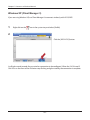
Windows XP (Wireless Zero Configuration).................................... 95
Mac OS X (Wi-Fi)............................................................................ 96
Chapter 6 - Troubleshooting............................................. 97
Cannot connect to the Internet over wired connection...............97
Cannot access the web-based configuration Interface..............97
Cannot connect to the network wirelessly..................................98
You forgot the AirStation's SSID, Encryption Key, or Password.98
-3-
The link speed is slower than 300 Mbps (Maximum link speed
is only 130 Mbps).......................................................................98
Other Tips..................................................................................99
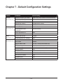
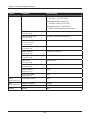
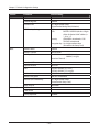
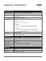
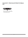
Chapter 7 - Default Configuration Settings..................... 101
-4-
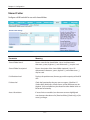
Chapter 1 - Product Overview
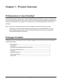
Professional or User-friendly?
This AirStation wireless router comes with two different firmware packages. You may use either the
dd-wrt-based professional firmware or the simple user-friendly firmware. By default, the professional
firmware is preinstalled. Turn to page 14 for instructions on switching between the two firmware
packages.
Note: Most of this manual documents the user-friendly version of the firmware. For more
information on the dd-wrt-based professional firmware, consult the help files in its webbased configuration interface or the User Manual for Professional Firmware, available for
download from Buffalo Technology.
Package Contents
The following items are included in your AirStation package. If any of the items are missing, please
contact your vender.
• WZR-600DHP................................................................................................................................. 1
• AC adapter...................................................................................................................................... 1
• Stand for vertical/horizontal/wall-mounting..................................................................... 1
• Screws for wall-mounting......................................................................................................... 2
• LAN cable........................................................................................................................................ 1
• AirStation Utility CD.................................................................................................................... 1
• Quick Setup Guide....................................................................................................................... 1
• Setup Card...................................................................................................................................... 1
-5-
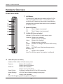
Chapter 1 Product Overview
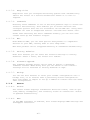
Hardware Overview
Front Panel LEDs
1
To initiate AOSS, hold down this button until the 2.4 GHz
LED and 5 GHz LED flash (about 1 second). Then, push
or click the AOSS button on your wireless client device to
complete the connection. Both devices must be powered
on for this to work.
1
2
3
2
4
Power LED (Green)
On:
Off:
5
3
6
The AC adapter is connected.
The AC adapter is not connected.
2.4 GHz LED (Green or Amber)
Indicates 2.4 GHz wireless LAN and security status.
Green on: Wireless link is enabled.
Wireless security is enabled.
Amber
Wireless link is enabled.
on:
Wireless security is disabled.
Green 2 AirStation is waiting for an AOSS or WPS security
blinks:
key.
Amber
AOSS/WPS error; failed to exchange security
blinking: keys.
Off:
Wireless LAN is disabled.
Note: The LED glows green if encryption is configured.
7
8
4
AOSS Button
5 GHz LED (Green or Amber)
Indicates 5 GHz wireless LAN and security status.
Green on:
Green 2 blinks:
Wireless link is enabled.
Wireless security is enabled.
Wireless link is enabled.
Wireless security is disabled.
AirStation is waiting for an AOSS or WPS security key.
Amber Blinking:
AOSS/WPS error; failed to exchange security keys.
Off:
Wireless LAN is disabled.
Amber on:
Note: The LED glows green if encryption is configured.
-6-
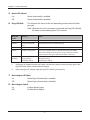
Chapter 1 Product Overview
5
6
7
Router LED (Green)
On:
Router functionality is enabled.
Off:
Router functionality is disabled.
Diag LED (Red)
This indicates the status of this unit depending on the number of blinks
per cycle.
Note: When the unit is first turned on or restarted, the Diag LED will blink
for almost a minute during boot. This is normal.
Diag LED
status
Meaning
Status
2 blinks *1
Flash ROM error
Cannot read or write to the flash memory.
3 blinks *
Ethernet (wired) LAN
error
Ethernet LAN controller is malfunctioning.
4 blinks *1
Wireless LAN error
Wireless LAN controller is malfunctioning.
5 blinks
IP address setting error
Because the network addresses of both the Internet port (WAN
port) and the LAN port are the same, it is not possible to establish
communication. Change the LAN side IP address of this unit.
Continuously
blinking *2
Updating the firmware
Saving settings
Initializing settings
Updating the firmware.
Saving the settings.
Initializing the settings.
*1
Unplug the AC adapter from the wall socket, wait for a few seconds, and then plug it again. If the
light still flashes, please contact technical support.
*2
Never unplug the AC adapter while the Diag LED is blinking continuously.
Movie Engine LED (Blue)
On:
Off:
8
1
Movie Engine functionality is enabled.
Movie Engine functionality is disabled.
Movie Engine Switch
On:
Off:
Enables Movie Engine.
Disables Movie Engine.
-7-
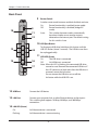
Chapter 1 Product Overview
Back Panel
9
ROUTER
ON
OFF
AUTO
10
USB
EJECT
USB
Switches router mode between enabled, disabled, and auto.
On:
Router functionality is enabled (router mode).
Off:
Router functionality is disabled (bridge/AP
mode).
Auto:
This switches between modes automatically
based on whether or not another router is
detected on the Internet port. The default setting
for this switch is Auto.
9
11
12
LAN
1
10
3
14
11
4
15
16
INTERNET
POWER
17
USB Eject Button
To dismount a USB drive, hold down this button until the
USB LED flashes (about 3 seconds). The USB drive can then
be unplugged safely.
2
13
Router Switch
USB LED (Green)
On:
The USB drive is connected.
Off:
No USB drive is connected.
Note: When this LED is blinking, the connected USB drive
cannot be used. Remove the connected USB drive. If
the LED continues to blink even after the USB drive is
removed, restart the AirStation.
Do not remove the USB drive or turn off the
AirStation while the USB LED is on.
12
USB Port
Connect the USB device.
13
LAN Port
Connect your computer, hub, or other Ethernet devices to these ports.
This switching hub supports 10 Mbps,100 Mbps, and 1000 Mbps
connections.
14
LAN LED (Green)
On:
An Ethernet device is connected.
Flashing:
An Ethernet device is communicating.
-8-
Chapter 1 Product Overview
15
Internet Port
16
Internet LED (Green)
17
10 Mbps, 100 Mbps, and 1000 Mbps connections are supported.
Note: In bridge/AP mode (router switch off ), the Internet port becomes a
regular LAN port, for a total of 5 usable LAN ports.
On:
The Internet port is connected.
Flashing:
The Internet port is transmitting data.
DC Connector
Connect the included AC adapter here.
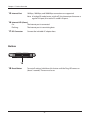
Bottom
18
18
Reset Button
To reset all settings, hold down this button until the Diag LED comes on
(about 3 seconds). Power must be on.
-9-
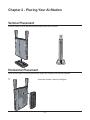
Chapter 2 - Placing Your AirStation
Vertical Placement
If the AirStation is to be placed vertically, attach the stand as shown.
Horizontal Placement
When installing the AirStation horizontally, attach the stand for best heat dissipation.
1
Attach the stand as shown in the figure.
- 10 -
Chapter 2 Placing Your AirStation
2
Install horizontally.
Wall Mounting
1
To wall-mount the AirStation, attach
the stand to the wall with the two
screws (included).
FRONT
8.6 cm
(~3.4 inches)
2
Snap the center of the AirStation to the stand as shown.
- 11 -
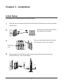
Chapter 3 - Installation
Initial Setup
To configure your AirStation, follow the procedure below.
1
Verify that you can connect to the internet without the AirStation, then turn off your modem
and computer.
2
Unplug the LAN cable which connects
your computer and modem.
2) disconnect
OFF
modem
computer
3
Make sure the mode switch on the back of
the AirStation is in the “auto” position.
ROUTER
ON
OFF
AUTO
Confirm that the
switch is positioned to
[AUTO].
4
USB
EJECT
Plug one end of the LAN cable into your modem and the other end to the AirStation’s
Internet (WAN) port. Turn on the modem.
modem
ROUTER
ON
OFF
AUTO
USB
EJECT
LAN cable
USB
1) connect
LAN
1
2
3
2) connect
4
INTERNET
POWER
AirStation
- 12 -
Internet
port
Chapter 3 Installation
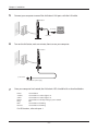
5
Connect your computer to one of the AirStation’s LAN ports with the LAN cable.
AirStation
ROUTER
ON
OFF
AUTO
USB
EJECT
USB
LAN
1
1) connect
2
3
2) connect
OFF
4
INTERNET
POWER
6
LAN cable
computer
Turn on the AirStation, wait one minute, then turn on your computer.
AirStation
ROUTER
ON
OFF
AUTO
USB
EJECT
USB
LAN
1
2
3
4
INTERNET
POWER
power outlet
1) Connect the power supply
7
Once your computer has booted, the AirStation’s LEDs should be lit as described below:
Power
2.4 GHz
5 GHz
Router
Diag
LAN
Internet
Green LED on.
Green LED on or amber light is on.
Green LED on or amber light is on.
Green LED on or off depending on your network.
Off
Green LED on or blinking.
Green LED on or blinking.
For LED locations, refer to chapter 1.
- 13 -
Chapter 3 Installation
8
Launch a web browser. If the home screen is displayed, setup is complete.
If username and password fields are displayed, enter “admin” for the username and
“password” for the password, then click [OK]. Step through the wizard to complete setup.
You’ve completed initial setup of your AirStation. Refer to Chapter 4 for advanced settings.
Changing Firmware
To change between the professional firmware (dd-wrt) and the user-friendly firmware, follow the
steps below.
1
Open the configuration Interface of the AirStation.
2
To replace the professional firmware with the user-friendly firmware, click [Administration] >
[Firmware Upgrade].
To replace the user-friendly firmware with the professional firmware, go to [Easy Setup] and
click [Update AirStation Firmware].
3
Click [Browse...] to select the firmware file, and click [Upgrade] or [Apply].
Note: The firmware files are contained in the “Firmware” folder of the utility CD.
Professional firmware (dd-wrt) update screen:
- 14 -
Chapter 3 Installation
User-friendly firmware update screen:
- 15 -
Chapter 4 - Configuration
The web-based configuration tool lets you change advanced settings for the AirStation. Don’t
change these settings unless you know what you’re doing.
Accessing the Web-based Configuration Interface
To configure the AirStation’s advanced settings manually, log in to the web-based configuration
interface as shown below.
1
Launch a web browser.
2
Enter the AirStation’s LAN-side IP address in the
address field and press the Enter key.
Note: ·
The AirStation’s default LAN-side IP address depends on the position of the mode switch.
In router mode: 192.168.11.1
In bridge mode: 192.168.11.100
Note:If the router switch is set to auto and the unit is in bridge mode, then the AirStation’s IP
address was assigned by an external DHCP server.
· If you changed the IP address of the AirStation, then use the new IP address.
3
Enter “admin” for the username and
“password” for the password and click [OK].
Note:If you forget your password, hold down the
reset button (page 9) to initialize all settings.
Note that all other settings will also revert to
their default values.
- 16 -
Chapter 4 Configuration
4
This is the configuration
interface, where most
AirStation settings can be
configured.
Help is always displayed on
the right side of each screen.
Refer to the help screens for
more information on using the
configuration interface.
- 17 -
Chapter 4 Configuration
Configuration Interface Menus in Router Mode
The menu structure for the AirStation in router mode is as follows. Please refer to the pages listed at
right for explanations of each item.
Main screen
Descriptions
Page
Internet
Configure Internet side port and settings.
Page 24
PPPoE
PPPoE settings (DSL login).
Page 25
DDNS
DNS settings.
Page 28
VPN Server
VPN server settings.
Page 30
LAN
LAN side port configuration.
Page 32
DHCP
DHCP lease settings.
Page 34
NAT
Network address translation settings, used to connect LAN side devices
to the Internet.
Page 35
Routing
Configure the AirStation’s IP communication route.
Page 36
WPS
WPS settings and status.
Page 37
Basic
Configure basic wireless settings.
Page 38
Advanced
Configure advanced wireless settings.
Page 41
WMM
Set priorities for Wireless Multimedia Extensions (Wi-Fi Multimedia).
Page 42
MAC Filter
Limit access to specific devices.
Page 44
AOSS
AOSS (AirStation One-touch Secure System) settings and status.
Page 45
Multicast Control
Configure limits on sending unnecessary multicast packets to the
wireless LAN port.
Page 47
Firewall
Protect your computer from outside intruders.
Page 48
IP Filter
IP filters for packets passing through the LAN side and the Internet side.
Page 50
VPN
Passthrough
Configure IPv6 passthrough, PPPoE passthrough, and PPTP passthrough.
Page 51
Port Forwarding
Configure port translation and exceptions for games and other
programs.
Page 52
DMZ
Configure a destination to transfer communication packets without a
LAN side destination.
Page 53
UPnP
Configure UPnP (Universal Plug and Play).
Page 54
QoS
Configure priority for packets that require a guaranteed data flow.
Page 55
WAN/LAN
Wireless
Firewall
Games/Apps
- 18 -
Chapter 4 Configuration
Movie Engine
Configure options for the Movie Engine feature.
Page 57
Disk Management
View the status and configure of attached USB disks.
Page 59
Shared Folder
Set the USB disk to use as shared folders.
Page 61
Users
Configure users to access shared folders.
Page 63
Sharing
Configure shared folder access.
Page 64
WebAccess
Configure Web Access.
Page 65
Media Server
Configure a Media Server.
Page 67
BitTorrent
Configure a BitTorrent client.
Page 68
Name
Configure the AirStation’s name.
Page 70
Password
Configure the AirStation’s login password for access to the configuration
interface.
Page 71
Time/Date
Configure the AirStation’s internal clock.
Page 72
NTP
Configure the AirStation to synchronize with an NTP server to
automatically set the AirStation’s internal clock.
Page 73
ECO
Configure the AirStation’s ECO Mode.
Page 74
Access
Configure access restrictions to the AirStation’s configuration interface.
Page 76
Log
Configure a syslog server to manage the AirStation’s logs.
Page 77
Save/Restore
Save or restore the AirStation’s configuration from a configuration file.
Page 78
Initialize/Restart
Initialize the AirStation or reboot it.
Page 79
Update
Update the AirStation’s firmware.
Page 80
System Info
View current system information for the AirStation.
Page 81
Logs
Check the AirStation’s logs.
Page 83
Packet Info
View all packets transferred by the AirStation.
Page 84
Client Monitor
View all devices currently connected to the AirStation.
Page 85
Ping
Test the AirStation’s connection to other devices on the network.
Page 86
NAS
Admin
Diagnostic
Logout
Click this to log out of the AirStation’s configuration interface.
Manuals & Utilities
Click this to display download pages for Manuals and Utilities.
- 19 -
Chapter 4 Configuration
Configuration Interface Menus in Bridge Mode
The menu structure in bridge mode is as follows. Please refer to the pages listed at right for
explanations of each item.
Main screen
Descriptions
Page
LAN
Configure LAN side ports and devices.
Page 32
Routing
Configure the AirStation’s IP communication route.
Page 36
WPS
WPS settings and status.
Page 37
Basic
Configure basic wireless settings.
Page 38
Advanced
Configure advanced wireless settings.
Page 41
WMM
Set priorities for Wireless Multimedia Extensions (Wi-Fi Multimedia).
Page 42
MAC Filter
Limit access to specific devices.
Page 44
AOSS
AOSS (AirStation One-touch Secure System) settings and status.
Page 45
Multicast Control
Configure limits on sending unnecessary multicast packets to the
wireless LAN port.
Page 47
Configure options for the Movie Engine feature.
Page 57
Disk Management
View the status and configure of attached USB disks.
Page 59
Shared Folder
Set the USB disk to use as shared folders.
Page 61
Users
Configure the name to access shared folders.
Page 63
Sharing
Configure the name to access shared folders.
Page 64
WebAccess
Set to use the Web Access function.
Page 65
Media Server
Set to use the Media Server function.
Page 67
BitTorrent
Set to use the BitTorrent function.
Page 68
Name
Configure the AirStation’s name.
Page 70
Password
Configure the AirStation’s login password for access to configuration
interface.
Page 71
Time/Date
Configure the AirStation’s internal clock.
Page 72
NTP
Configure the AirStation to synchronize with an NTP server to
automatically set the AirStation’s internal clock.
Page 73
LAN Config
Wireless
QoS
Movie Engine
NAS
Admin
- 20 -
Chapter 4 Configuration
ECO
Configure ECO Mode.
Page 74
Access
Configure access restrictions to the AirStation’s configuration interface.
Page 76
Log
Check the AirStation’s logs.
Page 77
Save/Restore
Save or restore the AirStation’s configuration from a configuration file.
Page 78
Initialize/Restart
Initialize the AirStation or reboot it.
Page 79
Update
Update the AirStation’s firmware.
Page 80
System Info
View current system information for the AirStation.
Page 81
Logs
Check the AirStation’s logs.
Page 83
Packet Info
View all packets transferred by the AirStation.
Page 84
Client Monitor
View all devices currently connected to the AirStation.
Page 85
Ping
Test the AirStation’s connection to other devices on the network.
Page 86
Diagnostic
Logout
Click this to log out of the AirStation’s configuration interface.
Manuals & Utilities
Click this to display download pages for Manuals and Utilities.
- 21 -
Chapter 4 Configuration
Setup
Setup is the home page of the configuration interface. You can verify settings and the status of the
AirStation here.
Parameter
Meaning
WAN/LAN (LAN Config)
Displays the configuration screen for the Internet port and LAN
ports.
Wireless
Click this button to display the configuration screen for wireless
settings.
Firewall
Click this button to display the configuration screen for security.
- 22 -
Chapter 4 Configuration
Parameter
Meaning
Games/Apps
Click this button to display the configuration screen to open ports
for games and applications.
NAS
Click this button to display the configuration screen for NAS
settings.
Admin
Click this button to display the configuration screen for
administration settings.
Diagnostic
Click this button to display the status of the AirStation.
Easy Setup
Enables you to easily configure the AirStation’s network settings
automatically.
Internet Connection
Displays WAN-side system information for the AirStation.
Check Connection
Click this button to check if the AirStation is connected to the
Internet properly.
Refresh
Click this button to refresh the current screen.
Wireless
Displays the current wireless settings.
AOSS Setup
Click this button to display the AOSS configuration screen.
WPS Setup
Click this button to display the WPS configuration screen.
ECO Mode
This indicates the operating status of ECO Mode.
Network Services
Displays the list of the network devices for which information is
provided from the network on the LAN-side.
Media Server
Displays the status of the media server.
Download Manager
Displays the list of BitTorrent files downloading.
Language
Enables you to select the language you use.
Logout
Log out of the configuration interface. If the AirStation does not
communicate for 5 minutes, it will log out automatically.
Manuals & Utilities
Click to display download pages for Manuals and Utilities.
- 23 -
Chapter 4 Configuration
WAN/LAN
Internet
Configure the WAN-side port (“Internet port”).
Parameter
Meaning
Method of Acquiring IP Address
Specify how the WAN-side IP address is obtained.
Default Gateway
Configure an IP address for the default gateway.
DNS Name Server Address
Specify an IP address for the DNS server.
Internet MAC Address
Configure the Internet side MAC address.
Note:Configuring an improper MAC address may make the AirStation
unusable. Change this setting at your own risk.
MTU Size of Internet Port
Configure the MTU value of the Internet port. Values of 578 to 1500
bytes may be entered.
- 24 -
Chapter 4 Configuration
PPPoE
Configure PPPoE settings.
Parameter
Meaning
Default PPPoE Connection
If you have registered multiple connection destinations in the
PPPoE Connection List, connection destinations selected here
have priority. You need to configure the route to which PPPoE is
connected to if you don’t use the default settings.
IP Unnumbered PPPoE Connection
Select the destination from the PPPoE Connection List which is
used when “Use IP Unnumbered” is chosen for the Method of
Acquiring IP Address (page 24).
PPPoE Connection List
Edit PPPoE destination. You can register up to 5 sessions.
Edit Connection List
Click this button to edit destination settings.
- 25 -
Chapter 4 Configuration
Parameter
Meaning
PPPoE Connection No.
This is displayed when [Edit Connection List] is clicked.
Name of Connection
Enter the name to identify the connected destination. You may
enter up to 32 alphanumerical characters and symbols.
Username
Enter the username specified by your ISP for PPPoE certification.
You may enter up to 64 alphanumerical characters and symbols.
Password
Enter the password specified by your ISP for PPPoE certification.
You may enter up to 64 alphanumerical characters and symbols.
Service Name
Fill in this field only if your ISP specifies a Service Name. Leave
blank otherwise. You may enter up to 64 alphanumerical
characters and symbols.
Connection Type
Specifies the timing for the AirStation to connect to your
provider.
Automatic Disconnection
Set time to disconnect after communication is stopped when
the connection method is set to [Connection on Demand] or
[Manual]. You can enter up to 1440 minutes.
Authorization
Configure an authorization method with a provider.
MTU Size
Configure the MTU size for PPPoE. Values of 578 to 1492 bytes
may be entered.
MRU Size
Configure MRU (Maximum Receive Unit) for PPPoE. Values of 578
to 1492 may be entered.
Keep Alive
If Keep Alive is enabled, then the AirStation will issue an LCP
echo request once a minute in order to maintain the connection
with the PPPoE. If the server does not respond for more than
6 minutes, the line is recognized as disconnected and the
AirStation will terminate the connection. Enabled by default.
- 26 -
Chapter 4 Configuration
Parameter
Meaning
Preferred Connections
Displays information you have set regarding to the connection
destination route.
Edit Preferred Connections
Click to edit the connection destination route settings.
Preferred PPPoE Connection
Click [Edit Preferred Connections] to display.
Name
This will be the name of the connection in the PPPoE connection
list.
Destination Address
The AirStation will always use this connection to send data to this
address.
Source Address
The AirStation will always use this connection to receive data
from this address.
- 27 -
Chapter 4 Configuration
DDNS
Configure Dynamic DNS settings. Many settings are only available when the appropriate Dynamic
DNS service is enabled.
Parameter
Meaning
Dynamic DNS Service
Select a provider (DynDNS or TZO) for dynamic DNS.
Username
Enter the dynamic DNS username. You may enter up to 64
alphanumerical characters and symbols.
Password
Enter the dynamic DNS password. You may enter up to 64
alphanumerical characters and symbols.
Hostname
Enter the dynamic DNS hostname. You may enter up to 255
alphanumerical characters, hyphens, and periods.
Email Address
Enter the email address which is registered to the dynamic DNS
service. You may enter up to 64 alphanumerical characters and
symbols.
TZO Key
Enter the TZO Key which is registered to the dynamic DNS service.
You may enter up to 64 alphanumerical characters and symbols.
Domain Name
Enter the domain name which is registered to the dynamic DNS
service. You may enter up to 255 alphanumerical characters,
hyphens, and periods.
- 28 -
Chapter 4 Configuration
Parameter
Meaning
IP Address Update Period
Specifies the period to notify the dynamic DNS service provider of
the current IP address. For DynDNS, set it between 0 and 35 days.
For TZO, set it between 0 and 99 days. If 0 (zero) days is set, no
periodic update is performed.
Internet-Side IP Address
The WAN-side IP address of the AirStation’s Internet port. This
address is sent to the dynamic DNS service provider.
Domain Name
The domain name assigned by the dynamic DNS Service provider.
The AirStation can be accessed from the Internet using this domain
name.
Status
Display the status of dynamic DNS service.
- 29 -
Chapter 4 Configuration
VPN Server
Configure the VPN server.
- 30 -
Chapter 4 Configuration
Parameter
Meaning
Auto Input
Click to generate a random IP address.
LAN Side IP Address
Set a LAN side IP address and subnet mask.
DHCP Server
Enable or disable the DHCP server, which assigns IP addresses
automatically.
DHCP IP Address Pool
Configure the range of IP addresses to be assigned by the DHCP
server and IP addresses to be excluded from that range. Values
from 1-256 may be entered.
PPTP Server
Enable to use a PPTP server.
Authorization Type
Select the authentication method for PPTP connection.
Server IP Address
Select the server IP address.
Client IP Address
Select the IP address range.
DNS Server IP Address
Choose the IP address for the DNS server.
WINS Server IP Address
Choose the IP address for the WINS server.
MTU/MRU Value
Configure MTU (Maximum Transmission Unit) / MRU (Maximum
Receive Unit) between 578 and 1500 which is used during
transmission on PPTP.
Edit PPTP User List
Click to edit user information.
Add new user
Click [Edit PPTP User List] to display.
Advanced Settings
Username
Enter the username to connect to the PPTP server. You may enter
up to 16 alphanumerical characters and symbols.
Password
Enter the password to connect to the PPTP server. You may enter
up to 16 alphanumerical characters and symbols.
Method of Acquiring IP Address
Select the method to be used to assign the IP address is assigned
to the PPTP client.
PPTP User List
Displays the PPTP connection user information.
- 31 -
Chapter 4 Configuration
LAN
Configure LAN-side and DHCP Server settings.
Parameter
Meaning
LAN Side IP Address
By default, the LAN side IP address is 192.168.11.1 with subnet
mask 255.255.255.0. You may change it here.
DHCP Server
Enable or disable the DHCP server, which assigns LAN-side IP
addresses automatically.
Router Mode only
DHCP IP Address Pool
Router Mode only
LAN Side IP Address
(For IP Unnumbered)
Configure the range of IP addresses to be assigned by the DHCP
server and IP addresses to be excluded from that range. Values
from 1-256 may be entered.
Set an IP unnumbered LAN side IP address.
Router Mode only
Note:A PC with a normal LAN side IP address and a PC with an IP
Unnumbered IP address cannot communicate each other.
Advanced Settings
Check [Display] to display DHCP server advanced settings options.
Router Mode only
Lease Period
Router Mode only
Default Gateway
Router Mode only
Set the effective period of an IP address assigned by the DHCP
server. Up to 999 hours may be entered.
Set the default gateway IP address for the DHCP server to issue to
clients.
- 32 -
Chapter 4 Configuration
Parameter
Meaning
DNS Servers
Set the DNS server IP address for the DHCP server to issue to
clients.
Router Mode only
WINS Server
Router Mode only
Set the WINS server IP address for the DHCP server to issue to
clients.
Router Mode only
Set the domain name for the DHCP server to issue to clients. You
may enter up to 64 alphanumerical characters, hyphens, and
periods.
Default Gateway
Set the default gateway IP address.
Domain Name
Bridge Mode only
DNS Server Address
Set the DNS server IP address.
Bridge Mode only
- 33 -
Chapter 4 Configuration
DHCP
Configure DHCP Exceptions.
Parameter
Meaning
IP Address
Enter an IP address to lease manually. The IP address should be
from the same subnet as the DHCP scope, but not be within the
range that DHCP is assigning to other devices.
MAC Address
Enter the MAC address which identifies the client.
Current DHCP Clients
Displays information for current leases. An IP address which is
leased automatically can be changed to manual leasing by clicking
[Manual Assignment].
- 34 -
Chapter 4 Configuration
NAT
Configure network address translation settings. This enables LAN-side devices to communicate with
the Internet.
Parameter
Meaning
Address Translation
Enable to use NAT (network address translation).
Log Output of Deleted Packets
Enable to log deleted packets (such as errors) during address
translation.
- 35 -
Chapter 4 Configuration
Routing
Configure the AirStation’s IP communication route.
Parameter
Meaning
Destination Address
Adds a destination IP address and subnet mask to a routing table.
Gateway
Adds a gateway address to a routing table.
Metric
The metric is the maximum number of router hops a packet may
take on the way to its destination address. Values between 1 and 15
may be entered. The default value is 15.
Routing
Manual entries will appear here after being added.
- 36 -
Chapter 4 Configuration
Wireless
WPS
WPS Status and Settings.
Parameter
Meaning
WPS
Enable to use WPS automatic configuration.
External Registrar
Enable to accept configure requests from other WPS devices.
Note: Configure requests will not be accepted if AOSS is in use.
AirStation PIN
Displays the PIN code of the AirStation. Clicking [Generate PIN]
will generate a new PIN code. This code can be entered into other
wireless devices that support WPS.
Enrollee PIN
Enter the PIN code for the other wireless device and click [OK].
WPS status
Displays “configured” if all available wireless bands are
configured. Displays “unconfigured” if at least one wireless band is
unconfigured.
- 37 -
Chapter 4 Configuration
Basic
The screen to configure a basic wireless settings.
Parameter
Meaning
Wireless Radio
Determines whether to allow wireless communication. If this is
unchecked, then no wireless connections will be allowed.
Wireless Channel
Sets a channel (a range of frequencies) for wireless connections.
With auto-channel selected, the AirStation will automatically use
the best available channel.
300 Mbps Mode
300 Mbps mode uses twice the normal frequency range, 40
MHz instead of 20 MHz. In uncongested areas this can increase
performance. To use 300 Mbps mode, set the bandwidth to 40 MHz
and choose an extension channel.
Note: If auto-channel is selected, then the extension channel is set
automatically.
- 38 -
Chapter 4 Configuration
Parameter
Meaning
Broadcast SSID
If [Allow] is checked, then the AirStation will respond to SSID
searches from wireless devices by broadcasting its SSID. If [Allow] is
unchecked, then the AirStation ignores SSID searches from wireless
devices.
Allow multiple SSIDs
Use Single SSID
Clicking [Allow multiple SSIDs] will enable Multi Security, allowing
the use of multiple SSIDs, each with different wireless security
settings. Clicking [Use Single SSID] will disable Multi Security.
The AirStation will then allow one SSID and one type of wireless
security.
Note:When using Multi Security, enable at least one of the following:
SSID1, SSID2, or SSID3.
SSID1
Multi Security SSID1 can use WPA-PSK-TKIP or WPA/WPA2-Mixed for
wireless security.
SSID2
Multi Security SSID2 can use WPA-PSK-AES for wireless security.
SSID3
Multi Security SSID3 can use WEP for wireless security.
Separate
When enabled, wireless devices connected to the AirStation can
communicate only with the Internet side, not with each other.
SSID
Set SSID using 1 - 32 alphanumeric characters.
Wireless Authentication
Specifies an authentication method used when connecting to a
wireless device.
- 39 -
Chapter 4 Configuration
Parameter
Meaning
Wireless Encryption
You may use any of the following types of encryption:
No encryption
Data is transmitted without encryption. With this setting, anyone
within range can connect to your wireless network and might
be able to access data on the network. Not recommended for
anyone with private data that needs to be kept secure. [No
encryption] can be selected only when [No authentication] is
selected for wireless authentication.
WEP
WEP is a common encryption method supported by most
devices. WEP can only be selected when wireless authentication
is set to [No authentication]. Note that WEP’s encryption is weak,
and networks protected with WEP are not much more secure
than those with no encryption at all. Not recommended for
anyone with private data that needs to be kept secure.
TKIP
TKIP is an encryption method which is more secure than WEP, but
slower.
TKIP can be selected only when WPA-PSK or WPA2-PSK is selected
for wireless authentication.
AES
AES is more secure than TKIP, and faster.
AES can be selected only when WPA-PSK or WPA2-PSK is selected
for wireless authentication.
TKIP/AES mixed mode
TKIP/AES mixed mode allows both TKIP and AES authentication
and communication. This is no more secure than TKIP alone, but
more convenient for some users. TKIP/AES mixed mode can be
selected only when WPA/WPA2 mixed mode - PSK is selected for
wireless authentication.
WPA-PSK (Pre-Shared Key)
A pre-shared key or passphrase is the password for your wireless
connections. There are two different formats for a pre-shared
key. Use 8 to 63 alphanumeric characters (case-sensitive) for an ASCII
passphrase, or use 64 alphanumeric characters (0 to 9 and a to f, not casesensitive) for a hexadecimal passphrase.
Rekey Interval
Set the update interval for the encryption key between 0 and 1440
(minutes).
- 40 -
Chapter 4 Configuration
Parameter
Meaning
Set up WEP encryption key
A WEP encryption key (passphrase) may have two different formats.
An ASCII passphrase may use either 5 or 13 alphanumeric characters
(case-sensitive). A hexadecimal passphrase may use either 10 or 26
alphanumeric characters (0 to 9 and a to f, not case-sensitive).
Advanced
Configure advanced wireless settings.
Parameter
Meaning
Multicast Rate
Set the communication speed of multi-cast packets.
DTIM Period
Set the beacon responding interval (1 -255) for which the AirStation
responds to a wireless device. This setting is effective only when
power management is enabled for the wireless device.
Privacy Separator
If enabled, the Privacy Separator blocks communication between
wireless devices connected to the AirStation. Wireless devices will
be able to connect to the Internet but not with each other. Devices
that are connected to the AirStation with wired connections will
still be able to connect to wireless devices normally.
- 41 -
Chapter 4 Configuration
WMM
Set priorities for specific communications.
- 42 -
Chapter 4 Configuration
Parameter
Meaning
WMM-EDCA Parameters
You don't usually need to change these settings. Using the default
settings is recommended.
Priority
The following priorities may be applied to individual
transmission packets: (Highest) 8, (High) 4, (Normal) 2, and
(Low) 1. From the queue, these packets are processed in order of
priority.
CWmin, CWmax
The maximum and minimum value of the contention window.
The contention window is used in the frame collision avoidance
structure performed in IEEE802.11, and generally, the smaller the
value in the window, the higher the probability that the queue
obtains the right to send.
AIFSN
The interval to send frames. The unit of the AIFSN is a slot, just as
the window defined by CWmin and CWmax is. The smaller the
interval of sending frames, the faster the algorithm can restart.
As a result, the priority of the queue is higher.
TXOP Limit
The period of time that the queue can use after obtaining the
right to send. The unit is 32 ms. The longer this time, the more
frames can be sent per right to send. However, the queue may
interfere with other packet transmissions. If TXOP Limit is set to 0
(zero), only one frame can be sent per right to send.
Admission Control
Restricts new frames from interfering with a previous queue. New
packets are prioritized lower until a queue of them is collected. As
the new queue accumulates more packets, its priority increases.
- 43 -
Chapter 4 Configuration
MAC Filter
Restrict access to specific wireless devices.
Parameter
Meaning
Enforce MAC Filtering
Enable to restrict wireless connections to devices with registered
MAC addresses.
Registration List
Displays the MAC addresses of registered devices which are
permitted to connect wirelessly.
Edit Registration List
Adds a wireless device to the list of permitted devices.
MAC Addresses to be Registered
Enter a MAC address of a wireless device to permit to connect to
the AirStation. Click [Register] to add that MAC address to the list.
List of all clients that are associated
with this AirStation
Display the list of all MAC addresses of wireless devices connected
to the AirStation.
- 44 -
Chapter 4 Configuration
AOSS
AOSS Status and Settings.
- 45 -
Chapter 4 Configuration
Parameter
Meaning
Initiates AOSS automatic wireless configuration. Click this, then
press or click the AOSS button on your AOSS-compatible wireless
client. Repeat for additional AOSS clients.
Click this button to disconnect AOSS connections.
Note:If AOSS connections are disconnected, the SSID and encryption keys
will be restored to their last settings from before AOSS was used.
Exclusive SSID for WEP
You may allow a separate SSID specifically for WEP connections. If
“disabled” is selected, then clients will not be able to connect with
WEP.
Encryption level expansion
Expands security method from TKIP to WPA/WPA2-PSK-mixed
mode.
Dedicated WEP SSID isolation
Set a separate SSID and network segment specifically for WEP
connections. Devices connected with WEP will not be able
to communicate with devices connected using AES/TKIP. All
connected devices will be able to communicate with the internet.
Allow WEP for Game Console Only
When enabled, the AirStation allows wireless devices to connect
with 64-bit or 128-bit WEP.
AOSS Button on the AirStation Unit
Uncheck to disable the physical AOSS button on the AirStation.
Current Encryption Information
Displays the encryption type, SSID, and encryption key configured
by AOSS.
(AOSS connection only)
Random
Click to enter random values for SSID, encryption key, and other
settings.
KEY base
Click to return the SSID, encryption key, and other wireless settings
to the values on the Setup Card.
Reset
Click to return the SSID, encryption key, and other wireless settings
to their previous values.
AOSS Client Information*
Displays AOSS clients connected to the AirStation and information
of the devices which are wirelessly communicated.
AOSS Ethernet Converter
Information*
Displays information about Ethernet converters connected to the
AirStation via AOSS.
*Only displayed if there are AOSS
Connections
- 46 -
Chapter 4 Configuration
Multicast Control
Configure restrictions on unnecessary multicast packets sent to the wireless LAN port.
Parameter
Meaning
Snooping
If enabled, snooping supervises multicast administrative packets
such as IGMP and restricts unnecessary multicast transfers to wired
or wireless ports.
Multicast Aging Time
Set the time to hold the data from multicast snooping in the range
of 1 to 3600 (seconds). Enter a value bigger than the IGMP/MLD
query interval.
- 47 -
Chapter 4 Configuration
Firewall
Firewall
Configure the AirStation’s firewall.
Parameter
Meaning
Log Output
Enable to output a log of firewall activity.
Basic Rules
Enable to use any of the quick filters. Preconfigured quick filters
include:
Prohibit NBT and Microsoft-DS routing
Enabling this blocks communication using these protocols from
the WAN side to the LAN side or from the LAN side to the Internet.
You can configure this with PPPoE if you select [Use PPPoE client]
or [Use IP unnumbered] in Method of Acquiring IP address (page
24), or if Easy Setup identified a PPPoE connection during setup.
- 48 -
Chapter 4 Configuration
Parameter
Meaning
Reject ident Requests
Enabling this option will answer IDENT requests from the Internet
side with corresponding rejection packets. Enable this option if
you experienced slow transfer speeds for network applications
such as mail, ftp or web browsing. If you have configured transfer
of IDENT requests to the LAN side computer in the address
translation settings (DMZ or TCP port 113), then that setting has
higher priority, and overrides this setting.
Block ping from Internet
If this is enabled, the AirStation will not respond to pings from the
Internet side. You can configure this with PPPoE if you select [Use
PPPoE client] or [Use IP unnumbered] in Method of Acquiring IP
address (page 24), or if Easy Setup identified a PPPoE connection
during setup.
- 49 -
Chapter 4 Configuration
IP Filter
Edit IP filters.
Parameter
Meaning
Log Output
If enabled, IP filter activity is saved to a log.
Operation
Specify how to process target packets.
Direction
Specify the transmission direction of target packets.
IP Address
Specify the sender's IP address and receiver's IP address of the
target packets.
Protocol
Select a protocol for target transmission packet.
IP Filter
Display the list of IP filters which have been registered.
- 50 -
Chapter 4 Configuration
VPN Passthrough
Configure IPv6 passthrough, PPPoE passthrough, and PPTP passthrough.
Parameter
Meaning
IPv6 Passthrough
Enable to use IPv6 Passthrough for address translation.
PPPoE Passthrough
Enable to use PPPoE bridging. PPPoE bridging lets you
automatically obtain an IP address from your provider for your LANside computer using the PPPoE protocol because PPPoE packets
can pass between the Internet and LAN.
PPTP Passthrough
Enable to use PPTP passthrough for address translation.
- 51 -
Chapter 4 Configuration
Games/Apps
Port Forwarding
Configure port translation.
Parameter
Meaning
Group
Specify a group name for a new rule to belong to. Select [New
Group] and enter the new group name in the Group Name
field to create a new group. A group name can include up to 16
alphanumeric characters.
Internet-Side IP Address
Enter the Internet side IP address (before translation) for the port
translation table entry.
Protocol
Select the Internet side protocol (before translation) for the port
translation table entry.
- 52 -
Chapter 4 Configuration
Parameter
Meaning
LAN Side IP Address
Enter the LAN side IP address (after translation) for the port
translation table entry.
LAN Side Port
Select the LAN side (after translation) port number (1 - 65535) for
the port translation table entry.
Forwarded Ports
Shows current entries in the port translation table.
DMZ
Configure a destination to transfer communication packets without a LAN side destination to.
Parameter
Meaning
IP Address of DMZ
Enter the IP address of the destination to which packets which are
not routed by a port translation table are forwarded.
Note: RIP protocol packets (UDP port number 520) will not be
forwarded.
- 53 -
Chapter 4 Configuration
UPnP
Configure UPnP (Universal Plug and Play).
Parameter
Meaning
UPnP
Enable or disable Universal Plug and Play (UPnP) functionality.
- 54 -
Chapter 4 Configuration
QoS
Configure the priority of packets sent to the Internet.
Parameter
Meaning
QoS for transmission to the Internet
Determine whether or not to prioritize packets sent to the Internet.
Check this box to enable QoS.
Uplink Bandwidth
Specify the upstream bandwidth in kbps from the AirStation to the
Internet side. Set the actual value for the upstream bandwidth.
Enable
Enable or disable this entry.
Application Name
Enter an application name. Names may use up to 32
alphanumerical characters, double or single tick marks ("'),
quotation marks (“), and semicolons (;).
Protocol
Select either TCP or UDP.
Destination Port
Specify a destination port from 1 - 65535. If this field is empty, a
random port is selected.
- 55 -
Chapter 4 Configuration
Parameter
Meaning
Priority
Select high, medium or low. If packets do not qualify for classification
as a type on the list, then their priority is treated as a level between
medium and low.
- 56 -
Chapter 4 Configuration
Movie Engine
Configure Movie Engine options.
- 57 -
Chapter 4 Configuration
Parameter
Meaning
Movie Engine Status
Displays the status of the Movie Engine switch.
IPv6 Passthrough
Set to enable the IPv6 pass-through.
Multicast Rate
Select the Multicast Control rate.
Multicast Control
Turn on Multicast Control.
TCP Rwin Size Limit
Limits the maximum size of TCP Rwin packets passing through the
AirStation’s wireless LAN.
Wireless Priority Control Rules
Display the list of rules controlling the priority of packets passing
through the AirStation’s wireless LAN.
- 58 -
Chapter 4 Configuration
NAS
Disk Management
View the status of and configure attached USB hard disks.
Parameter
Meaning
Device
Displays information for attached USB drives. To dismount a drive,
click [Remove] in the Device column.
Disk
A disk number will be automatically assigned to the drive or you
can choose a number. Select a drive number, or select [Do not
assign], then click [Apply].
Partition
Displays the partition information for the selected USB drive. Click
[Format] to format the drive. Note: formatting a drive will erase all
information on it.
Re-recognize USB Devices
Click this to re-scan for connected USB drives.
- 59 -
Chapter 4 Configuration
Parameter
Meaning
Automatic USB Disk Assignment
Check [Enable] to automatically select an attached USB hard disk.
The entire drive will be used as the shared folder. To configure your
disk and share manually, uncheck [Enable]. [Enable] is selected by
default.
FAT Format Filename Character Code
Select the character code for filenames in FAT formatted partitions.
Sleep Mode
Click [Enable] to enable Sleep Mode.
Sleep Mode Interval
Powers down the device after this duration of time.
- 60 -
Chapter 4 Configuration
Shared Folder
Configure a USB hard disk for use with shared folders.
Parameter
Meaning
Shared Folder Name*
Enter a name for the shared folder. Up to 18 alphanumeric
characters, spaces, hyphens (-), and underscores (_) may be used.
Shared Folder Description*
Enter a description of the shared folder (optional). Up to 75
alphanumeric characters, spaces, hyphens (-), and underscores (_)
may be used.
Disk Partition Area*
Displays the partition area, format type, and the capacity of the USB
disk.
Disclosed to*
Check the functionality that you want to support. Win/Mac OS
(Samba NAS), Web Access, Media Server, and/or BitTorrent may be
checked. Only one folder may be chosen for either Media Server or
BitTorrent functionality.
Access Restrictions
If access limits are enabled, use the arrows to move highlighted
users between the columns for [Read and Write], [Read only], or [No
access] privileges.
- 61 -
Chapter 4 Configuration
Parameter
Meaning
WebAccess
You may also select to enforce access limits on users accessing
through Web Access by checking the Access Restrictions checkbox.
Users will have the same access levels as assigned above. If Access
Restrictions is not checked, then all users accessing the shared
folder via Web Access will have [Read only] access.
Shared Folder Registration
Information*
Displays information about the shared folder.
*This is not displayed when Automatic USB Disk Assignment (page 60) is used:
The following shared folder settings are used when Disk Management is activated:
• All folders: Access limits in effect.
• Shared Folder/ Web Access: All folders are shared.
• Media Server/BitTorrent: The first folder is shared.
- 62 -
Chapter 4 Configuration
Users
This screen lets you add users to the access list with the ability to access shared folders.
Parameter
Meaning
Username
Enter the name of a user to be given access to the shared folder.
Up to 20 alphanumeric characters, space, hyphens (-), underscores
(_), and periods (.) may be used for each user. Up to 16 users may
be entered.
Password
Enter the user’s password. Use of the same password that
they use to log into their computer is recommended. Up to 20
alphanumeric characters, spaces, hyphens (-), and underscores
(_) may be used. For Windows 98SE/98/95 users, up to 14
alphanumeric characters may be used. Mac OS users may use up
to 8 alphanumeric characters. If you enter a longer password than
your users can use, then they will not be able to access the share.
User Description
Describe the user (optional). Up to 75 alphanumeric characters,
spaces, hyphens (-), and underscores (_) may be used.
Current Users
Lists current users, including “guest”. Guest is a built-in account
that cannot be changed or deleted.
- 63 -
Chapter 4 Configuration
Sharing
Assign AirStation and workgroup names to access shared folders.
Parameter
Meaning
Shared Folder
Enable to make a USB disk available on your local network.
AirStation Name
Rename your AirStation if desired. Up to 15 alphanumeric
characters, space, and hyphens (-) may be used. The AirStation
name is also used as the hostname that will be used with the
shared service. The shared service may not be available you use
over 15 alphanumeric characters in your AirStation’s name.
AirStation Description
Describe the AirStation (optional). Up to 48 alphanumeric
characters, space, hyphens (-), and underscores (_) may be used.
Workgroup Name
Enter your workgroup name. Up to 15 alphanumeric characters,
space, hyphens (-), underscores (_), and periods (.) may be used.
Windows Client Language
Select the language to be used by the Windows client.
Shared Service
Displays the status of the USB disk that is used with the shared
service.
- 64 -
Chapter 4 Configuration
WebAccess
The screen to configure Web Access.
Parameter
Meaning
WebAccess
Check [Enable] to use Web Access.
WebAccess Display Language
Set the language to be used with Web Access.
HTTPS/SSL Encryption
Check [Enable] to use SSL encryption for protected data transfer.
WebAccess External Port
Automatically sets the external port used for Web Access. To select
the port manually, select [Manual].
DNS Service Hostname
Sets the DNS service hostname for WebAccess. For ease of use, selecting
Use BuffaloNAS.com registration is recommended. Enter your BuffaloNAS.
com name and key] to use BuffaloNAS.com. 3 - 20 alphanumeric
characters, spaces, hyphens (-), underscores (_) and period (.), may be
used in the BuffaloNAS.com name. 3 - 20 alphanumeric characters, spaces,
hyphens (-), underscores (_) and period (.), may be used in the BuffaloNAS.
com key.
Note: The registered name is deleted from the server if the AirStation is
disconnected from power, even for a moment.
- 65 -
Chapter 4 Configuration
Parameter
Meaning
WebAccess
Displays the status of Web Access.
External Port Status
Displays the status of the external port.
BuffaloNAS.com
Displays the status of BuffaloNAS.com.
- 66 -
Chapter 4 Configuration
Media Server
Media Server settings.
Parameter
Meaning
Media Server
Enable to use the media server.
Status
Displays the status of the media server.
- 67 -
Chapter 4 Configuration
BitTorrent
Configure the BitTorrent client.
Parameter
Meaning
BitTorrent
Enable to use the BitTorrent client. If the BitTorrent client is
enabled, overall communication performance may decrease and
settings screens may respond slower. If that happens, reformat the
USB disk with XFS. That may help performance.
External Port Number
Select an external port number.
- 68 -
Chapter 4 Configuration
Parameter
Meaning
Bandwidth Restriction
Set a bandwidth limit for BitTorrent.
Download Manager
Displays the BitTorrent download manager screen. Add a torrent,
then click [Add] to download the file(s).
Delete all BitTorrents
Deletes all files, including the torrent files and files which are
currently downloading. Downloaded files are not deleted.
BitTorrent Status
Displays the status of the BitTorrent client.
BitTorrent External Port Status
Display the external port status of the BitTorrent client.
You can download the latest Windows BitTorrent client from www.bittorrent.com.
- 69 -
Chapter 4 Configuration
Admin
Name
Configure basic AirStation settings.
Parameter
Meaning
AirStation Name
Enter a name for the AirStation. Names may include up to 64
alphanumeric characters and hyphens (-).
Network Services
Enable or disable this to display the computers and devices on your
network with their supported services.
- 70 -
Chapter 4 Configuration
Password
Configure the password to log in to the AirStation’s configuration screen.
Parameter
Meaning
Administrator
The name of the Administrator account is “admin”.
Administrator Password
The Administrator password may contain up to 8 alphanumeric
characters and underscores (_).
- 71 -
Chapter 4 Configuration
Time/Date
Configure the AirStation’s internal clock.
Parameter
Meaning
Local Date
You may manually set the date of the AirStation’s internal clock.
Local Time
You may manually set the time of the AirStation’s internal clock.
Time Zone
Specify the time zone (offset of Greenwich Mean Time) of the
AirStation's internal clock.
DST (Daylight Saving Time)
You may configure the AirStation to automatically use DST
(Daylight Saving Time). If selected, the AirStation will automatically
adjust the time at the beginning and end of DST.
- 72 -
Chapter 4 Configuration
NTP
Configure an NTP server to automatically synchronise the AirStation’s internal clock.
Parameter
Meaning
NTP Functionality
Enable to use an NTP server. The default is Enabled.
NTP Server
Enter the name of the NTP server as a hostname, hostname with
domain name, or IP address. Up to 255 alphanumeric characters,
hyphens (-), and periods (.) may be used. The default is “time.nist.
gov”.
Update Interval
How often will the AirStation check the NTP server for the correct
time? Intervals of 1 - 24 hours may be set. The default is 24 hours.
- 73 -
Chapter 4 Configuration
ECO
Configure Eco mode from this screen.
- 74 -
Chapter 4 Configuration
Parameter
Meaning
Scheduling
Enable to schedule Eco Mode. If Eco mode is enabled, AOSS will
function only when the AirStation is in Normal operating mode.
Weekly Schedule
Graphically displays the configured schedule.
Schedule Entry
Configure operational mode for time periods in the weekly
schedule. If User Defined mode is chosen, configure it below.
User Defined Mode
Individual power saving elements may be configured for User
Defined mode.
- 75 -
Chapter 4 Configuration
Access
Restrict access to the AirStation’s settings screens.
Parameter
Meaning
Log Output
Enabling outputs a log of changes to access settings.
Prohibit configuration from wireless
LAN
If enabled, prevents access to settings screens from wirelessly
connected devices (only wired devices may configure).
Prohibit configuration from wired
LAN
If enabled, prevents access to settings screens from wired devices
(only wirelessly connected devices may configure).
Permit configuration from wired
Internet
If enabled, allows access to settings screens from network devices
on the WAN (Internet) side.
Permitted IP Address
Displayed only if Internet side configuration is enabled. Enter the
IP address of a device that is permitted to configure the AirStation
remotely from the WAN (Internet) side.
Permitted Port
Displayed only if Internet side configuration is enabled. Set a port
number (1 - 65535) to configure the AirStation from the WAN
(Internet) side.
- 76 -
Chapter 4 Configuration
Log
Transfer the AirStation’s logs to a syslog server.
Parameter
Meaning
Transfer Logs
Enable to send logs to a syslog server.
Syslog Server
Identify the syslog server by hostname, hostname with domain
name, or IP address. You may enter up to 255 alphanumeric
characters, hyphens (-), and periods (.).
Logs
Choose which logs will be transferred to the syslog server.
- 77 -
Chapter 4 Configuration
Save/Restore
Save AirStation settings as a file, and restore from them later.
Parameter
Meaning
Save Current Settings
Clicking [Save] will save the current configuration of the AirStation
to a file. If the [Encrypt the configuration file with a password]
option is checked, then the configuration file will be password
protected with the password.
Restore Configuration from Backup
File
Restore the configuration of the AirStation from a saved
configuration file by clicking the [Browse...] button, navigating to
the configuration file, and then clicking Restore. If the configuration
file was password protected, then put a check next to [Enter
password], enter the password, and click [Restore].
- 78 -
Chapter 4 Configuration
Initialize/Restart
Initialize or restart the AirStation.
Parameter
Meaning
Restart
Click [Restart Now] to restart the AirStation.
Initialize
Click [Initialize Now] to initialize and restart the AirStation.
- 79 -
Chapter 4 Configuration
Update
Update the AirStation’s firmware.
Parameter
Meaning
Firmware Version
Displays the current firmware version of the AirStation.
Update Method
Specify Local File
Updates from a firmware file stored on your computer.
Auto Update Online
Automatically updates to the latest firmware available.
Firmware File Name
Click [Browse...] to navigate to the firmware file on your computer
if [Specify Local File] was selected. You don’t need to specify the
firmware location if you’re using [Auto Update Online]. Click
[Update Firmware] to update the firmware.
- 80 -
Chapter 4 Configuration
Diagnostic
System Info
View system information for the AirStation.
- 81 -
Chapter 4 Configuration
Parameter
Meaning
Model
Displays the product name of the AirStation and the firmware
version.
AirStation Name
Displays the name of the AirStation.
Mode Switch Status
Displays the status of the AirStation’s mode switch.
Operational Mode
Displays the AirStation’s current operational mode.
Movie Engine Status
Displays the current Movie Engine Status.
Internet
Displays information about the Internet port.
LAN
Displays information about the LAN port.
Wireless
Displays the wireless status.
NAS
Displays information about the USB disk.
ECO Mode
Displays the operating status of ECO Mode.
- 82 -
Chapter 4 Configuration
Logs
The AirStation’s logs are recorded here.
Parameter
Meaning
Display logs
Choose the logs.
Logs
Displays the logs.
- 83 -
Chapter 4 Configuration
Packet Info
View packet transfer information.
Parameter
Meaning
Sent
Displays the number of packets sent to the WAN, the LAN, and the
wireless LAN.
Received
Displays the number of packets received from the WAN, the LAN,
and the wireless LAN.
- 84 -
Chapter 4 Configuration
Client Monitor
This screen shows devices that are connected to the AirStation.
Parameter
Meaning
Client Monitor
Displays information (MAC address, lease IP address, hostname,
communication method, wireless authentication, and 802.11n) for
devices that are connected to the AirStation.
- 85 -
Chapter 4 Configuration
Ping
A ping test checks whether the AirStation can communicate with a specific network device.
Parameter
Meaning
Destination Address
Enter the IP address or hostname of the device that you are testing
communication with, then click [Execute]. The result will be
displayed below.
- 86 -
Chapter 5 - Connect to a Wireless Network
Automatic Secure Setup (AOSS/WPS)
AOSS and WPS are systems that let you automatically configure wireless LAN settings. Just pressing
the buttons will connect wireless devices and complete security settings. Easily connect to wireless
devices, computers, or game machines which support AOSS or WPS.
AOSS (AirStation One-Touch Secure System) was developed by Buffalo Technology. WPS
was created by the Wi-Fi Alliance.
Internet
PUSH
Modem
PUSH
AirStation
PC or
Game console
(AOSS Devices)
• Before using AOSS/WPS to connect to a Buffalo wireless client, install Client Manager software from
the included utility CD. Consult your wireless client’s documentation for more information.
• Buffalo’s Client Manager software can be used with the wireless LAN devices built into most
computers. However, it is not guaranteed to work with all wireless LAN devices available. Some
wireless clients may require manual setup.
- 87 -
Chapter 5 Connect to a Wireless Network
Windows 7/Vista (Client Manager V)
If you are using Windows 7 or Vista, use the included Client Manager V software to connect
wirelessly with AOSS/WPS.
1
2
3
Click [Start] > [All Programs] > [BUFFALO] > [AirStation Utility] > [Client Manager V].
Click [Create Profile].
If the User Account Control screen opens, click [Yes] or [Continue].
4
Click the [WPS AOSS ] button.
Follow any instructions displayed on the screen. When the 2.4 GHz and 5 GHz LEDs on the front of
the AirStation stop flashing and is lit steadily, the connection is complete.
- 88 -
Chapter 5 Connect to a Wireless Network
Windows XP (Client Manager 3)
If you are using Windows XP, use Client Manager 3 to connect wirelessly with AOSS/WPS.
1
Right click on the
icon in the system tray and select [Profile].
2
Click the [WPS AOSS] button.
It will take several seconds for your wireless connection to be configured. When the 2.4 GHz and 5
GHz LEDs on the front of the AirStation stop flashing and glow steadily, the connection is complete.
- 89 -
Chapter 5 Connect to a Wireless Network
Mac OS X (AOSS Assistant)
If you are using Mac OS X 10.7 / 10.6 / 10.5 / 10.4, use the included AOSS Assistant software to
connect wirelessly with AOSS.
1
Load the utility CD in your Macintosh.
2
From the menu bar, click [Go] > [Computer].
3
Double-click the CD icon, and then double-click [AOSS Assistant] in the “Mac” folder.
4
The software license screen is displayed. Click [Agree] to proceed.
5
Click [Start AOSS ].
6
Enter the Mac’s username and
password and click [OK].
It will take several seconds for your wireless connection to be configured. When the 2.4 GHz and 5
GHz LEDs on the front of the AirStation stop flashing and glow steadily, the connection is complete.
- 90 -
Chapter 5 Connect to a Wireless Network
Other Devices (e.g. Game Console)
If you are using a game machine which supports AOSS or WPS, refer to that device’s manual to
initiate AOSS/WPS. When instructed, hold down the AOSS button on the AirStation for 1 second.
When the 2.4 GHz and 5 GHz LEDs on the front of the AirStation stop flashing and glow steadily, the
connection is complete.
Manual Setup
You can also connect to the AirStation without installing Client Manager V or Client Manager 3 by
using the utility built-in to Windows. The procedure varies depending on which version of Windows
you are using.
Windows 7 (WLAN AutoConfig)
With Windows 7, use WLAN AutoConfig to connect to the AirStation.
1
Click on the network
icon in the system tray.
2
Select the target AirStation and click
[Connect]. If you will be connecting to this
device in the future, checking [Connect
automatically] is recommended.
- 91 -
Chapter 5 Connect to a Wireless Network
3
Enter the encryption key and click [OK].
Windows Vista (WLAN AutoConfig)
With Vista, use WLAN AutoConfig to connect to the AirStation.
1
Right click on the wireless network
2
Click [Connect to a network].
icon in the system tray.
3
When this screen is displayed, select your
network and click [Connect].
- 92 -
Chapter 5 Connect to a Wireless Network
If the screen below is displayed, click [I want to enter the network key or passphrase instead].
Otherwise,go to step4.
- 93 -
Chapter 5 Connect to a Wireless Network
4
Enter the encryption key and click [Connect].
Step through the wizard to finish configuration.
If the Set Network Location screen is displayed, select [Home], [Work], or [Public location] depending
on where you’re using the AirStation.
- 94 -
Chapter 5 Connect to a Wireless Network
Windows XP (Wireless Zero Configuration)
Windows XP includes Wireless Zero Config, a built-in utility to connect to your AirStation.
Note: If Client Manager 3 is installed on your computer, Wireless Zero Config is disabled. Uninstall Client
Manager 3 to use Wireless Zero Config, or just use Client Manager 3 to connect to the AirStation.
1
Right click on the
2
Click [View Available Wireless Networks].
wireless network icon in the system tray.
3
Select the network to connect to and click
[Connect].
4
Enter the encryption key (twice) and click
[Connect].
It will take several seconds for configuration to complete.
- 95 -
Chapter 5 Connect to a Wireless Network
Mac OS X (Wi-Fi)
Use Wi-Fi on a Mac to connect to the AirStation.
Note:
In Mac OS X 10.6 and earlier, “Wi-Fi” appears as “AirPort”.
1
Refer to the Setup Card. Make a note of the
SSID and Key printed on the Setup Card.
2
Click the
icon in the top
section of the screen and select
[Turn Wi-Fi On].
3
Find the SSID from step 1 on the list.
Click it to highlight it.
4
Enter the KEY from step 1 into
the Password entry box, check
[Remember this network], and click
[OK].
It will take several seconds for configuration to complete.
- 96 -
Chapter 6 - Troubleshooting
Cannot connect to the Internet over wired connection.
• Make sure that your AirStation is plugged in!
• Check that the status LEDs of your AirStation are lit as below:
Power
Router
Diag
LAN
Internet
Green LED is ON
Green LED is ON or OFF (depending on your environment)
OFF
Green LED is ON or flashing
Green LED is ON or flashing
• Make sure that your computer is set to [obtain an IP address automatically]. (Appendix C)
• Restart your AirStation.
Cannot access the web-based configuration Interface.
• See chapter 4 for instructions to open the AirStation’s configuration interface.
• Enter the correct username and password to log in to the configuration interface. If you are using
AirStation with factory default settings, enter “admin” for the username and “password” for the
password.
• Verify that your web browser is not set to use proxies.
• Make sure that your computer is configured to [Obtain an IP Address Automatically.] (Appendix C)
• Restart your AirStation.
- 97 -
Chapter 6 Trouble Shooting
Cannot connect to the network wirelessly.
• Configure your wireless client with the same SSID, encryption type, and encryption key as set on the AirStation.
The factory defaults are:
SSID -
BUFFALO-XXXXXX (the last 6 digits of the AirStation’s MAC address) + “_A“ or “_G“
Encryption Type -
WPA/WPA2 mixed mode - PSK (Connect with either WPA-PSK TKIP or WPA2-PSK AES).
Encryption Key -
Printed on the Setup Card.
Note:
For details, refer to the Setup Card.
• Place your AirStation and wireless devices 2 - 10 feet apart.
• Restart your AirStation.
You forgot the AirStation's SSID, Encryption Key, or
Password.
Hold down the reset button on the base of your AirStation for 3 seconds to initialize its settings. All
settings, including your password, SSID, and encryption key will be initialized to their defaults.
The link speed is slower than 300 Mbps (Maximum
link speed is only 130 Mbps).
By default, the AirStation’s 300 Mbps mode is not enabled. You may enable it with the following
procedure:
1. Open the configuration interface (chapter 4).
2. In Easy Setup, click [Wireless SSID & Channel (11n 300 Mbps Mode)].
3. Change the value in [300 Mbps Mode] - [Bandwidth] to 40 MHz and click [Apply].
If you still cannot connect at 300 Mbps, check the settings of your wireless client devices.
- 98 -
Chapter 6 Trouble Shooting
Other Tips
Issue:
I reset my wireless router to factory settings and forgot how to log in to the configuration interface.
Answer:
Open your browser, enter 192.168.11.1 as the browser address, and hit Enter. You will be prompted
to log in. Enter “admin” for the username and “password” for the password. Click [OK] to log in. The
option to reset your password will be available on the first page.
Issue:
How do I forward ports on my wireless router for my gaming console?
Answer:
Log in to the router’s configuration interface. From the home page, go to the Internet Games/Apps
section. Enter the port that needs to be forwarded and the IP address of the gaming console.
Issue:
How do I enable or modify security encryption settings on the wireless router?
Answer:
Log in to the configuration interface with your browser. Go to [Wireless] - [Basic]. Buffalo
recommends WPA for wireless encryption. The passphrase/key should be at least 8 characters in
length.
Issue:
How do I change my wireless router’s broadcasted network name (SSID)?
Answer:
Log in to the wireless router with your browser. Navigate to [Wireless] - [Basic]. Find the SSID setting.
Select [Use] and enter the new name for your network. Click [Apply]. Once the wireless router has
rebooted, you will need reconnect any wireless clients to the AirStation using the new network
name. The encryption key will still be the same.
- 99 -
Chapter 6 Trouble Shooting
Issue:
What can I do if my wireless connection drops randomly or seems slow?
Answer:
There are many environmental factors that may cause this. First, ensure the issue is not range
related by moving the wireless router and the client device closer together. If the connection drops
continue, then range is probably not the issue.
Other 2.4 GHz devices such as microwaves, other wireless networks, and 2.4 GHz wireless phones
may impact performance. Try a different wireless channel for your wireless router. Log in to the
wireless router with your browser. Click on [Wireless] - [Basic]. Wireless channels from 1 - 11 may be
selected. Try the Auto-Channel option if available. Otherwise, manually select an alternate channel
and click [Apply].
Issue:
Though I am able to successfully make a connection with my wireless router, I am unable to access
the Internet with my web browser.
Answer:
First, power off the Cable or DSL modem, the wireless router, and your computer. Move the router's
mode switch to the on position. Verify that the modem is connected to the wireless router with an
Ethernet cable to the WAN port. Power on the modem and wait one minute. Power on the wireless
router and wait another minute. Power on the computer. Open a browser on the computer and
navigate to a familiar website to verify whether the Internet connection is functioning normally.
If after these steps, an Internet connection is still unavailable, power off the Cable or DSL modem
and computer again and directly connect your computer to the Cable or DSL modem with a cable
between the computer and the port on the modem. Power on the modem and wait one minute.
Power on the computer and again check for an Internet connection.
If an Internet connection IS NOT available with a direct connection to the computer, please call the
Internet Service Provider who installed the modem.
If an Internet connection IS available with a direct connection to the computer, please call our
customer support.
Issue:
Where can I download the latest drivers, firmware, and instructions for my Buffalo wireless products?
Answer:
The latest drivers and firmware are available online at
www.buffalotech.com
- 100 -
Chapter 7 - Default Configuration Settings
Feature
Parameter
Default Setting
Internet
Method of Acquiring IP Address
Perform Easy Setup (Internet Connection Wizard)
(Router Mode only)
Default Gateway
None
DNS Name Server Address
None
Internet MAC Address
Use default MAC address
MTU Size of Internet Port
1500 Bytes
PPPoE
Default PPPoE Connection
No Active Session
(Router Mode only)
IP Unnumbered PPPoE
Connection
No Active Session
PPPoE Connection List
None
Preferred Connections
None
DDNS
Dynamic DNS Service
Disabled
(Router Mode only)
Current Dynamic DNS Settings
None
VPN Server
LAN Side IP Address
192.168.11.1(255.255.255.0)
(Router Mode only)
DHCP Server
Enabled
DHCP IP Address Pool
192.168.11.2 for up to 64 Address(es)
PPTP Server
Disabled
Authorization Type
MS-CHAPv2 (40/128-bit Encryption)
Server IP Address
Auto
Client IP Address
Auto
DNS Server IP Address
LAN IP address of the AirStation
WINS Server IP Address
None
MTU/MRU value
1396
PPTP User List
None
- 101 -
Chapter 7 Default Configuration Settings
Feature
Parameter
Default Setting
LAN
LAN Side IP Address
Router Mode (Router Switch AUTO/ON):
192.168.11.1 (255.255.255.0)
Bridge Mode (Router Switch OFF):
192.168.11.100 (255.255.255.0)
Bridge Mode (Router Switch AUTO):
Obtain automatically from DHCP Server
DHCP Server
Enabled
(Router Mode only)
DHCP IP Address Pool
192.168.11.2 for up to 64 Addresses
(Router Mode only)
LAN Side IP Address
None
(For IP Unnumbered)
(Router Mode only)
Lease Period
48 Hours
(Router Mode only)
Default Gateway
AirStation's IP Address
(Router Mode only)
DNS Servers
AirStation's IP Address
(Router Mode only)
WINS Server
Do Not Specify
(Router Mode only)
Domain Name
Assigned Domain Name
(Router Mode only)
Default Gateway
None
(Bridge Mode only)
DNS Server Address
None
(Bridge Mode only)
DHCP
Current DHCP Clients
None
(Router Mode only)
NAT
Address Translation
Enabled
(Router Mode only)
Log Output of Deleted Packets
Disabled
Routing
Routing
None
- 102 -
Chapter 7 Default Configuration Settings
Feature
Parameter
Default Setting
WPS
WPS
Enabled
External Registrar
Enabled
AirStation PIN
An 8-digit random value
(Printed on the label of the AirStation)
WPS Security Settings
WPS status:
SSID:
Wireless Radio
Enabled
Wireless Channel
Auto Channel
300 Mbps Mode
Band Width:
Broadcast SSID
Allow
Separate Feature
Not used
SSID
BUFFALO-XXXXXX_A (11n/a)
BUFFALO-XXXXXX_G (11n/g/b)
Wireless Authentication
WPA/WPA2 mixedmode - PSK
Wireless Encryption
TKIP/AES mixedmode
WPA-PSK (Pre-Shared Key)
An 8-digit random value
(Printed on the Setup Card)
Rekey Interval
60 minutes
Multicast Rate
Auto
DTIM Period
1
Privacy Separator
Disabled
Basic
Advanced
configured
BUFFALO-XXXXXX (the last 6 digits
of the AirStation’s MAC address) +
“_A” or “_G”
Security:WPA/WPA2 mixedmode - PSK
TKIP/AES mixedmode
Encryption key:An 8-digit random value
(Printed on the Setup Card)
40 MHz (11n/a)
20 MHz (11n/g/b)
Extension Channel: -
- 103 -
Chapter 7 Default Configuration Settings
Feature
Parameter
WMM
WMM-EDCA Parameters
(Priority AC_BK (Low) )
Default Setting
WMM-EDCA Parameters
(Priority AC_BE (Normal) )
WMM-EDCA Parameters
(Priority AC_VI (High) )
WMM-EDCA Parameters
(Priority AC_VO (Highest) )
MAC Filter
AOSS
Multicast
Control
For AP
For STA
CWmin
15
15
CWmax
1023
1023
AIFSN
7
7
TXOP Limit
0
0
Admission Control
-----
Disabled
For AP
For STA
CWmin
15
15
CWmax
63
1023
AIFSN
3
3
TXOP Limit
0
0
Admission Control
-----
Disabled
For AP
For STA
CWmin
7
7
CWmax
15
15
AIFSN
1
2
TXOP Limit
94
94
Admission Control
-----
Disabled
For AP
For STA
CWmin
3
3
CWmax
7
7
AIFSN
1
2
TXOP Limit
47
47
Admission Control
-----
Disabled
Enforce MAC Filtering
Disabled
Registration List
None
Exclusive SSID for WEP
None
Encryption level expansion
Enabled
Dedicated WEP SSID isolation
Disabled
Allow WEP for Game Console Only
Disabled
AOSS Button on the AirStation
Unit
Enabled
Snooping
Enabled
Multicast Aging Time
300 Sec.
- 104 -
Chapter 7 Default Configuration Settings
Feature
Parameter
Default Setting
Firewall
Log Output
Disabled
(Router Mode only)
Basic Rules
Prohibit NBT and Microsoft-DS routing
Reject ident requests
Block ping from Internet
IP Filter
Log Output
Disabled
(Router Mode only)
IP Filter
None
VPN Passthrough IPv6 Passthrough
Disabled
(Router Mode only)
PPPoE Passthrough
Disabled
PPTP Passthrough
Enabled
Forwarded Ports
None
IP Address of DMZ
None
UPnP
Enabled
QoS for transmission to the
Internet
Disabled
(Router Mode only)
Movie Engine
Movie Engine Status
off
IPv6 Passthrough
Used
Multicast Rate
11 Mbps
Multicast Control
Snooping Aging Time
Change Priority
TCP Rwin Size Limit
Size Limit
No limit
Maximum Rwin Size 65535 bytes
Wireless Priority Control Rules
None
Automatic USB Disk Assignment
Enabled
FAT Format Filename Character
Code
North America (CP437)
Sleep Mode
Not used
Sleep Mode Interval 10 Minutes
Access Restrictions
Read and Write
WebAccess
Access Restrictions
Current Users
guest
Port Forwarding
(Router Mode only)
DMZ
(Router Mode only)
UPnP
(Router Mode only)
QoS
Disk
Management
Shared Folder
Users
- 105 -
Use
300 Seconds
VI (priority)
Disabled
Enabled
Enabled
Chapter 7 Default Configuration Settings
Feature
Parameter
Default Setting
Sharing
Shared Folder
Enabled
AirStation Name
AP + AirStation’s MAC Address
AirStation Description
None
Workgroup Name
WORKGROUP
Windows Client Language
North America (CP437) Shared Service
None
WebAccess
Disabled
WebAccess Display Language
English
HTTPS/SSL Encryption
Disabled
WebAccess External Port
Auto (Port Number:9000)
DNS Service Hostname
Use BuffaloNAS.com registration
WebAccess Status
None
Media Server
Disabled
Status
None
BitTorrent
Disabled
External Port Number
Auto (Port Number: 9002)
Bandwidth Restriction
Enabled
Maximum Download Speed 1000 KB/s
Maximum Upload Speed 200 KB/s
BitTorrent Status
None
AirStation Name
AP + AirStation's MAC Address
Network Services
Enabled
Administrator
admin (fixed)
Administrator Password
password
Local Date
2012 Year 1 Month 1 Day
Local Time
0 Hour 0 Minute 0 Seconds
Time Zone
(GMT-6:00) Central Standard Time - CST
DST (Daylight Saving Time)
USA (from second Sunday to in Mar to first Sunday
in Nov)
NTP Functionality
Enabled
NTP Server
time.nist.gov
Update Interval
24 hours
WebAccess
Media Server
BitTorrent
Name
Password
Time/Date
NTP
- 106 -
Chapter 7 Default Configuration Settings
Feature
Parameter
Default Setting
ECO
Scheduling
Disabled
Schedule Entry
Operational Mode:
Start time:
End time:
The day of week:
Normal
0:00
0:30
None
User Defined Mode
LED:
Wired LAN:
Wireless LAN:
Off
ECO (Slow operation)
Off
Log Output
Disable
Management Access
Prohibit configuration from wireless LAN Disabled
Prohibit configuration from wired LAN Disabled
Permit configuration from wired Internet Disabled
Transfer Logs
Disabled
Syslog Server
None
Logs
Router Mode:
Address Translation, IP Filter, Firewall, PPPoE
Client, Dynamic DNS, DHCP Client, DHCP Server,
AOSS, Wireless Client, Authentication, Setting
Changes, System Boot, NTP Client, and Wired Link
Bridge Mode:
IP Filter, DHCP Client, AOSS, Wireless Client,
Authentication, Setting Changes, System Boot,
NTP Client, and Wired Link
Access
Log
- 107 -
Appendix A - Specifications
Wireless LAN Interface
Standard Compliance
IEEE802.11a / IEEE802.11b / IEEE802.11g / IEEE802.11n
Transmission Method
Direct Sequence Spread Spectrum (DSSS), OFDM, MIMO
802.11a Frequency Range Available 802.11a frequencies depend on the country of purchase. See the next
page for details.
802.11g Frequency Range 2,412 - 2,462 MHz (Channels 1 - 11)
Transmission Rate
802.11b:
11, 5.5, 2, 1 Mbps
802.11a/g:
54, 48, 36, 24, 18, 12, 9, 6 Mbps
802.11n
20MHz BW
(LongGI) 130, 117, 104, 78, 52, 39, 26, 13 Mbps (2 stream)
65, 58.5, 52, 39, 26, 19.5, 13, 6.5 Mbps (1 stream)
40MHz BW
(LongGI) 270, 243, 216, 162, 108, 81, 54, 27 Mbps (2 stream)
135, 121.5, 108, 81, 54, 40.5, 27, 13.5 Mbps (1 stream)
(ShortGI) 300 Mbps (2 stream)
Access Mode
Infrastructure Mode
Security
AOSS, WPA2-PSK (TKIP/AES), WPA/WPA2 mixed PSK, WPA-PSK (TKIP/AES), 128 /
64bit WEP, Mac Address Filter
Wired LAN Interface
Standard Compliance
IEEE802.3ab (1000BASE-T), IEEE802.3u (100BASE-TX), IEEE802.3 (10BASE-T)
Transmission Rate
10 / 100 / 1000 Mbps
Transmission Encoding
1000BASE-T 4DPAM5, 100BASE-TX 4B5B/MLT-3, 10BASE-T Manchester Coding
Access Method
CSMA/CD
Speed and Flow Control
10 / 100 / 1000 Mbps, Auto Sensing, Auto MDIX
Number of LAN Ports
4
LAN Port Connector
RJ-45
USB Interface
Interface
USB 2.0
Connector Type
Type A (plug)
Compliance
5.0 V 500 mA (max 1000 mA)
-1-
Appendix A Specifications
Other
Power Supply
External AC 100-240 V Universal, 50/60 Hz
Power Consumption
About 13.2 W (Max)
Dimensions
165 mm x 158 mm x 35mm (6.5 x 6.2 x 1.3 in.)
Weight
340 g (11.6 oz.) (not including the stand)
Operating Environment
0 - 40° C (32 - 104° F), 20 - 80% (non-condensing)
802.11a Frequency Range
USA
Canada
5,180 - 5,240 MHz (Channels 36, 40, 44, 48)
5,745 - 5,825 MHz (Channels 149, 153, 157, 161, 165)
-2-
Appendix B - Checking Wireless Signal Quality
For users of Windows 7, Vista, or Mac OS X (10.4 and later), software supplied with the AirStation can
be used to check the quality and strength of the wireless signal.
Windows 7/Vista
Note: ·If Client Manager V is not already installed, install it from the utility CD.
1
·Client Manager V does not support Windows XP.
Click the
icon in the system tray.
2
Click [Advanced Setup].
3
When the Client Manager V status screen is
displayed, click
.
-3-
Appendix B Checking the Wireless Signal Quality and Strength
4
Parameter
Meaning
Connection status
Signal strength (dBm), link speed (Mbps), and signal quality (%) are
displayed in one-minute intervals on a real-time graph.
Usage status by channel
The 11b/11g display shows usage in the 2.4 GHz band channels 1
to 14.
The 11a display shows usage in the W52, W53, and W56 channels.
Colors are used to indicate the signal strength of the access point. Colors closer to red indicate an
access point with a stronger signal strength, and colors closer to blue indicate an access point with a
weaker signal strength.
Macintosh
1
Load the utility CD into your Macintosh.
2
From the menu bar, click [Go] > [Computer].
3
Double-click the CD icon, and then double-click [WLAN Monitor] in the “Mac” folder.
-4-
Appendix B Checking the Wireless Signal Quality and Strength
4
The software license screen is displayed when starting for the first time only. Click [Agree] to
proceed.
5
Parameter
Meaning
Network name (SSID)
This displays the SSID of the AirStation that is currently connected.
Status
This indicates the current connection status.
IP Address
This indicates the IP address of the current wireless network port
(Wi-Fi).
Security
This indicates the authentication method for the current
connection target.
Encryption
This displays the encryption type for the current connection target.
Band
This displays the wireless band for the current connection target.
Channel
This displays the wireless channel for the current connection target.
Link Speed (Mbps)
This displays the current link speed.
Quality (%)
This displays the current signal quality.
Signal Level (dBm)
This indicates the strength of the current signal.
-5-
Appendix C - TCP/IP Settings
Windows 7
To configure TCP/IP in Windows 7, follow the procedure below.
1
Click [Start] > [Control Panel] > [Network and Internet].
2
Click [Network and Sharing Center].
3
Click [Change Adapter Settings] on the left side menu.
4
Right-click on [Local Area Connection], then click [Properties].
5
If the User Account Control screen opens, click [Yes] or [Continue].
6
Select [Internet Protocol Version 4 (TCP/IPv4)] then click [Properties].
7
To have DHCP set your IP address settings automatically, check [Obtain an IP address
automatically] and [Obtain DNS server address automatically].
To set your IP address settings manually, enter values for each setting. Examples:
8
If the router’s IP address is 192.168.11.1,
IP address
192.168.11.80
Subnet mask
255.255.255.0
Default gateway
192.168.11.1
Preferred DNS server
192.168.11.1
Alternate DNS server
blank
Click [OK].
-6-
Appendix C TCP/IP Settings
Windows Vista
To configure TCP/IP in Windows Vista, follow the procedure below.
1
Click [Start] > [Settings] > [Control Panel].
2
Click [Network and Sharing Center].
3
Click [Manage network connections] on the left side menu.
4
Right-click on [Local Area Connection], then click [Properties].
5
If the User Account Control screen opens, click [Yes] or [Continue].
6
Select [Internet Protocol Version 4 (TCP/IPv4)], then click [Properties].
7
To have DHCP set your IP address settings automatically, check [Obtain an IP address
automatically] and [Obtain DNS server address automatically].
To set your IP address settings manually, enter values for each settings. Example:
8
If the router’s IP address is 192.168.11.1,
IP address
192.168.11.80
Subnet mask
255.255.255.0
Default gateway
192.168.11.1
Preferred DNS server
192.168.11.1
Alternate DNS server
blank
Click [Close].
-7-
Appendix C TCP/IP Settings
Windows XP
To configure TCP/IP in Windows XP, follow the procedure below.
1
Click [Start] > [Settings] > [Control Panel].
2
Double-click [Network].
3
Right click on [Local Area Connection], then click [Properties].
4
Select [Internet Protocol (TCP/IP)], then click [Properties].
5
To have DHCP set your IP address settings automatically, check [Obtain an IP address
automatically] and [Obtain DNS server address automatically].
To set your IP address settings manually, enter values for each setting. Examples:
6
If the router’s IP address is 192.168.11.1,
IP address
192.168.11.80
Subnet mask
255.255.255.0
Default gateway
192.168.11.1
Preferred DNS server
192.168.11.1
Alternate DNS server
blank
Click [Close].
-8-
Appendix C TCP/IP Settings
Mac OS X
To configure TCP/IP in Mac OS X, follow the procedure below.
1
Click [Apple menu] > [System Preferences…].
2
Click [Network].
3
Click [Ethernet].
4
To have DHCP set your IP address settings automatically, select [Using DHCP] in the Configure
IPv4 field.
To set your IP address settings manually, select [Manually] in the Configure IPv4 field and
enter values for each setting. Examples:
5
If the router’s IP address is 192.168.11.1,
IP Address
192.168.11.80
Subnet Mask
255.255.255.0
Router
192.168.11.1
DNS Server
192.168.11.1
Search Domains
blank
Click [Apply].
-9-
Appendix D - Restoring the Default Configuration
With the AirStation powered on, hold
down this button for 3 seconds to return
it to factory default settings.
- 10 -
Appendix E - Shared Folders and the USB Port
There are several restrictions on using the AirStation’s USB port:
• When using two-byte characters (such as Japanese), keep folder and file names within 80
characters. You may not be able to copy a folder or a file whose name length is more than 80
characters.
• You cannot set attributes (hidden or read-only) for folders or files on the AirStation.
• When using access restrictions, you can register up to 16 users for the AirStation.
• Please note that you are not allowed to use any of the following words as a user or group name:
adm, administrator, all, bin, daemon, disk, ftp, guest, halt, hdusers, kmen, lp, mail, man, news,
nobody, nogroup, none, operator, root, shadow, shutdown, sshd, sync, sys, ttyusers, utmp, uucp,
www.
• Please note that you are not allowed to use any of the following words as a shared folder name:
global, homes, printers, bittorrent, disk1_pt1, disk1_pt2, disk1_pt3, disk1_pt4, disk2_pt1, disk2_
pt2, disk2_pt3, disk2_pt4, disk3_pt1, disk3_pt2, disk3_pt3, disk3_pt4, disk4_pt1, disk4_pt2, disk4_
pt3, disk4_pt4.
• If a file created on a Macintosh contains any of the following characters, it will not be displayed
correctly under Windows OS. Also, you cannot copy or properly display a file when connecting via
SMB from Mac OS X if it contains any of these characters:
? [ ] / \ = + < > ; : ”, | *
• Cancelling or aborting a file copy may leave the file incomplete, and you may no longer be able
to delete the incomplete file. This can also happen during a power outage or if the LAN cable is
suddenly disconnected. If it happens, restart the AirStation, delete the file, and try copying the file
again.
• Use the same username and password for the AirStation as the user’s Windows login. If they
are different, the user may not be able to access shared folders with access restrictions on the
AirStation.
• Date and time stamps stored on the USB hard drive may be updated by the OS accessing the
AirStation. File creation or access dates may not be maintained.
• If you view the size of a hard drives on the browser, it shows a bigger value than when you see it in
Windows’ drive properties. This is because the browser shows the size of the drive in gigabytes but
Windows shows it in gibibytes.
- 11 -
Appendix E Technical Detail of the USB port
• If you have logged in using a “guest” account from Windows 7, Vista, XP or 2000, access restrictions
may not work properly. A (different) guest account already exists on the AirStation.
• If you access a shared folder from a Macintosh computer, additional Mac OS X information files
may be automatically generated. Do not delete these files from a Windows computer. Otherwise,
you may no longer be able to access folders from a Macintosh.
• Device types that can be connected to the AirStation’s USB connector are USB hard drives, USB
memory sticks, or USB card readers. Card readers with 5 or more slots are not supported. USB
devices such as a digital cameras, CD/DVD drives, USB hubs, mice, or keyboards are not supported.
• Encrypted USB hard drives are not supported.
• Only one single drive may be connected to the AirStation’s USB port at a time. Drives
manufactured by other companies besides Buffalo Technology are not supported.
• If your hard drive has an auto power mode switch, move the switch to [manual] or [on]. Leaving
the switch set to [auto] may result in unpredictable behavior.
• Up to 4 partitions can be recognized on a USB hard drive.
• Available file systems for USB hard drives are FAT12, FAT16, FAT32, and XFS.
- 12 -
Appendix F - Regulatory Compliance Information
Federal Communication Commission Interference Statement
This equipment has been tested and found to comply with the limits for a Class B digital device,
pursuant to Part 15 of the FCC Rules. These limits are designed to provide reasonable protection
against harmful interference in a residential installation. This equipment generates, uses and can
radiate radio frequency energy and, if not installed and used in accordance with the instructions,
may cause harmful interference to radio communications. However, there is no guarantee that
interference will not occur in a particular installation. If this equipment does cause harmful
interference to radio or television reception, which can be determined by turning the equipment off
and on, the user is encouraged to try to correct the interference by one of the following measures:
• Reorient or relocate the receiving antenna.
• Increase the separation between the equipment and receiver.
• Connect the equipment into an outlet on a circuit different from that to which the receiver is
connected.
• Consult the dealer or an experienced radio/TV technician for help.
FCC Caution:
Any changes or modifications not expressly approved by the party responsible for compliance could
void the user’s authority to operate this equipment.
For operation within 5.15 ~ 5.25GHz frequency range, it is restricted to indoor environment.
This device complies with Part 15 of the FCC Rules. Operation is subject to the following two
conditions: (1) This device may not cause harmful interference, and (2) this device must accept any
interference received, including interference that may cause undesired operation.
Important Note - FCC Radiation Exposure Statement:
This equipment complies with FCC radiation exposure limits set forth for an uncontrolled
environment. This equipment should be installed and operated with minimum distance 20cm
between the radiator & your body.
This transmitter must not be co-located or operating in conjunction with any other antenna or
transmitter.
The availability of some specific channels and/or operational frequency bands are country
dependent and are firmware programmed at the factory to match the intended destination. The
firmware setting is not accessible by the end user.
WZR-600DHP with PCB Dipole antenna and max. antenna gain is 3.13 dBi in 2.4G and 3.04 dBi in 5G.
- 13 -
Appendix F Regulatory Compliance Information
Industry Canada statement:
This device complies with RSS-210 of the Industry Canada Rules. Operation is subject to the
following two conditions:
(1) This device may not cause harmful interference, and
(2) this device must accept any interference received, including interference that may cause
undesired operation.
Ce dispositif est conforme à la norme CNR-210 d’Industrie Canada applicable aux appareils radio
exempts de licence. Son fonctionnement est sujet aux deux conditions suivantes:
(1) le dispositif ne doit pas produire de brouillage préjudiciable, et
(2) ce dispositif doit accepter tout brouillage reçu, y compris un brouillage susceptible de provoquer
un fonctionnement indésirable.
Caution:
The device for the band 5150-5250 MHz is only for indoor usage to reduce potential for harmful
interference to co-channel mobile satellite systems.
High power radars are allocated as primary users (meaning they have priority) of 5250-5350 MHz
and 5650-5850 MHz and these radars could cause interference and/or damage to LE-LAN devices.
Le dispositif fonctionnant dans la bande 5150-5250 MHz est réservé uniquement pour une
utilisation à l’intérieur afin de réduire les risques de brouillage préjudiciable aux systèmes de
satellites mobiles utilisant les mêmes canaux.
Les utilisateurs de radars de haute puissance sont désignés utilisateurs principaux (c.-à-d., qu’ils ont
la priorité) pour les bandes 5250-5350 MHz et 5650-5850 MHz et que ces radars pourraient causer
du brouillage et/ou des dommages aux dispositifs LAN-EL.
Important Note - Canada Radiation Exposure Statement:
This equipment complies with Canada radiation exposure limits set forth for an uncontrolled
environment. This equipment should be installed and operated with minimum distance 20cm
between the radiator and your body.
NOTE IMPORTANTE: (Pour l’utilisation de dispositifs mobiles)
Déclaration d’exposition aux radiations:
Cet équipement est conforme aux limites d’exposition aux rayonnements IC établies pour un
environnement non contrôlé. Cet équipement doit être installé et utilisé avec un minimum de 20 cm
de distance entre la source de rayonnement et votre corps.
Europe – EU Declaration of Conformity
This device complies with the essential requirements of the R&TTE Directive 1999/5/EC. The
following test methods have been applied in order to prove presumption of conformity with the
essential requirements of the R&TTE Directive 1999/5/EC:
- 14 -
Appendix F Regulatory Compliance Information
EN60950-1: 2006 +A11: 2009
Safety of Information Technology Equipment
EN50385 : (2002-08)
Product standard to demonstrate the compliance of radio base stations and fixed terminal stations
for wireless telecommunication systems with the basic restrictions or the reference levels related to
human exposure to radio frequency electromagnetic fields (110MHz - 40 GHz) - General public
EN 300 328 V1.7.1: (2006-10)
Electromagnetic compatibility and Radio spectrum Matters (ERM); Wideband Transmission systems;
Data transmission equipment operating in the 2,4 GHz ISM band and using spread spectrum
modulation techniques; Harmonized EN covering essential requirements under article 3.2 of the
R&TTE Directive
EN 301 893 V1.5.1: (2008-12)
Broadband Radio Access Networks (BRAN); 5 GHz high performance RLAN; Harmonized EN covering
the essential requirements of article 3.2 of the R&TTE Directive
EN 301 489-1 V1.8.1: (2008-04)
Electromagnetic compatibility and Radio Spectrum Matters (ERM); ElectroMagnetic Compatibility
(EMC) standard for radio equipment and services; Part 1: Common technical requirements
EN 301 489-17 V2.1.1 (2009-05)
Electromagnetic compatibility and Radio spectrum Matters (ERM); ElectroMagnetic Compatibility
(EMC) standard for radio equipment; Part 17: Specific conditions for Broadband Data Transmission
Systems
This device is a 2.4 GHz wideband transmission system (transceiver), intended for use in all EU
member states and EFTA countries, except in France and Italy where restrictive use applies.
In Italy the end-user should apply for a license at the national spectrum authorities in order to
obtain authorization to use the device for setting up outdoor radio links and/or for supplying public
access to telecommunications and/or network services.
This device may not be used for setting up outdoor radio links in France and in some areas the
RF output power may be limited to 10 mW EIRP in the frequency range of 2454 – 2483.5 MHz. For
detailed information the end-user should contact the national spectrum authority in France.
- 15 -
Appendix F Regulatory Compliance Information
Česky [Czech]
Buffalo Technology Inc. tímto prohlašuje, že tento AirStation WZR-600DHP je ve shodě se základními
požadavky a dalšími příslušnými ustanoveními směrnice 1999/5/ES.
Dansk [Danish]
Undertegnede Buffalo Technology Inc. erklærer herved, at følgende udstyr AirStation WZR-600DHP
overholder de væsentlige krav og øvrige relevante krav i direktiv 1999/5/EF.
Deutsch [German]
Hiermit erklärt Buffalo Technology Inc. dass sich das Gerät AirStation WZR-600DHP in
Übereinstimmung mit den grundlegenden Anforderungen und den übrigen einschlägigen
Bestimmungen der Richtlinie 1999/5/EG befindet.
Eesti [Estonian]
Käesolevaga kinnitab Buffalo Technology Inc. seadme AirStation WZR-600DHP vastavust direktiivi
1999/5/EÜ põhinõuetele ja nimetatud direktiivist tulenevatele teistele asjakohastele sätetele.
English
Hereby, Buffalo Technology Inc. declares that this AirStation WZR-600DHP is in compliance with the
essential requirements and other relevant provisions of Directive 1999/5/EC.
Español [Spanish]
Por medio de la presente Buffalo Technology Inc. declara que el AirStation WZR-600DHP cumple
con los requisitos esenciales y cualesquiera otras disposiciones aplicables o exigibles de la Directiva
1999/5/CE.
Ελληνική [Greek]
ΜΕ ΤΗΝ ΠΑΡΟΥΣΑ Buffalo Technology Inc. ΔΗΛΩΝΕΙ ΟΤΙ AirStation WZR-600DHP ΣΥΜΜΟΡΦΩΝΕΤΑΙ
ΠΡΟΣ ΤΙΣ ΟΥΣΙΩΔΕΙΣ ΑΠΑΙΤΗΣΕΙΣ ΚΑΙ ΤΙΣ ΛΟΙΠΕΣ ΣΧΕΤΙΚΕΣ ΔΙΑΤΑΞΕΙΣ ΤΗΣ ΟΔΗΓΙΑΣ 1999/5/ΕΚ.
Français [French]
Par la présente Buffalo Technology Inc. déclare que l’appareil AirStation WZR-600DHP est conforme
aux exigences essentielles et aux autres dispositions pertinentes de la directive 1999/5/CE.
Italiano [Italian]
Con la presente Buffalo Technology Inc. dichiara che questo AirStation WZR-600DHP è conforme ai
requisiti essenziali ed alle altre disposizioni pertinenti stabilite dalla direttiva 1999/5/CE.
Latviski [Latvian]
Ar šo Buffalo Technology Inc. deklarē, ka AirStation WZR-600DHP atbilst Direktīvas 1999/5/EK
būtiskajām prasībām un citiem ar to saistītajiem noteikumiem.
Lietuvių [Lithuanian]
Šiuo Buffalo Technology Inc. deklaruoja, kad šis AirStation WZR-600DHP atitinka esminius
- 16 -
Appendix F Regulatory Compliance Information
reikalavimus ir kitas 1999/5/EB Direktyvos nuostatas.
Nederlands [Dutch]
Hierbij verklaart Buffalo Technology Inc. dat het toestel AirStation WZR-600DHP in overeenstemming
is met de essentiële eisen en de andere relevante bepalingen van richtlijn 1999/5/EG.
Malti[ Maltese]
Hawnhekk, Buffalo Technology Inc. , jiddikjara li dan AirStation WZR-600DHP jikkonforma malħtiġijiet essenzjali u ma provvedimenti oħrajn relevanti li hemm fid-Dirrettiva 1999/5/EC.
Magyar [Hungarian]
Alulírott, Buffalo Technology Inc. nyilatkozom, hogy a AirStation WZR-600DHP megfelel a vonatkozó
alapvetõ követelményeknek és az 1999/5/EC irányelv egyéb elõírásainak.
Polski [Polish]
Niniejszym Buffalo Technology Inc. oświadcza, że AirStation WZR-600DHP jest zgodny z
zasadniczymi wymogami oraz pozostałymi stosownymi postanowieniami Dyrektywy 1999/5/EC.
Português [Portuguese]
Buffalo Technology Inc. declara que este AirStation WZR-600DHP está conforme com os requisitos
essenciais e outras disposições da Directiva 1999/5/CE.
Slovensko [Slovenian]
Buffalo Technology Inc. izjavlja, da je ta AirStation WZR-600DHP v skladu z bistvenimi zahtevami in
ostalimi relevantnimi določili direktive 1999/5/ES.
Slovensky [Slovak]
Buffalo Technology Inc. týmto vyhlasuje, že AirStation WZR-600DHP spĺňa základné požiadavky a
všetky príslušné ustanovenia Smernice 1999/5/ES.
Suomi [Finnish]
Buffalo Technology Inc. vakuuttaa täten että AirStation WZR-600DHP tyyppinen laite on direktiivin
1999/5/EY oleellisten vaatimusten ja sitä koskevien direktiivin muiden ehtojen mukainen.
Svensk [Swedish]
Härmed intygar Buffalo Technology Inc. att denna AirStation WZR-600DHP står I överensstämmelse
med de väsentliga egenskapskrav och övriga relevanta bestämmelser som framgår av direktiv
1999/5/EG.
Taiwan:
- 17 -
Appendix F Regulatory Compliance Information
SAR compliance has been established in typical laptop computer(s) with CardBus slot, and product
could be used in typical laptop computer with CardBus slot. Other application like handheld PC or
similar device has not been verified, may not comply with related RF exposure rules, and such use
shall be prohibited.
Safety
This equipment is designed with the utmost care for the safety of those who install and use it.
However, special attention must be paid to the dangers of electric shock and static electricity when
working with electrical equipment. All guidelines of this manual and of the computer manufacturer
must therefore be allowed at all times to ensure the safe use of the equipment.
根據 NCC 低功率電波輻射性電機管制辦法:
第十二條:
經型式認證合格之低功率射頻電機,非經許可,公司、商號或使用者均不得擅自變更頻率、加
大功率或變更原設計之特性及功能。
第十四條:
低功率射頻電機之使用不得影響飛航安全及干擾合法通信;經發現有干擾現象時,應立即停
用,並改善至無干擾時方得繼續使用。前項合法通信,指依電信法規定作業之無線電通信。低
功率射頻電機須忍受合法通信或工業、科學及醫療用電波輻射性電機設備之干擾。
5.25-5.35秭赫頻帶內操作之無線資訊傳輸設備,限於室內使用。
기종별
B 급 기기
( 가정용 정보통신기기 )
사용자안내문
이 기기는 가정용 (B 급 ) 전자파적합기기로서 주
로 가정에서 사용하는 것을 목적으로 하며 , 모든
지역에서 사용할 수 있습니다 .
- 18 -
Appendix G - Environmental Information
• The equipment that you have purchased has required the extraction and use of natural resources
for its production.
• The equipment may contain hazardous substances that could impact health and the environment.
• In order to avoid the dissemination of those substances in our environment and to diminish the
pressure on the natural resources, we encourage you to use the appropriate take-back systems.
• The take-back systems will reuse or recycle most of the materials of your end life equipment in a
sound way.
• The crossed-out wheeled bin symbol invites you to use those systems.
• If you need more information on collection, reuse, and recycling systems, please contact your local
or regional waste administration.
- 19 -
Appendix H - GPL Information
The source code for Buffalo products that use GPL code is available at http://opensource.buffalo.jp/ .
- 20 -