1
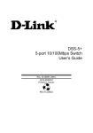
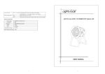
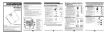
Automotive Leak Locator
ALL-100 User Manual
1
Structure Instruction
Main Unit
a) Operation film
b) Flow regulating Valve
c) Prompt Light
d) Power Switch & Fuse Holder
e) Battery Jump Cable
f) Smoke Output Tube
g) Dip Stick (Checking oil level)
h) Handle
Accessories
i) Cap Stopples
j) Exhaust Cone Adaptor
k) OBD-II Service Port Adaptor
l) Schrader Valve Removal Tool
m) Bottle Oiler
n) Flashlight
Components and Accessories Details
The following list is designed to familiarize you with thelocation and
function of the operational components of themachine. The list also
includes the supplied accessories andhow to use them.
a) Operation film
The LED display set time with two digital. Set operation time by press
“time” key. Start or stop operation by press “Start/Stop” key.
b) Flow Control Valve
2
In many cases excessive smoke exiting a leak may make it difficult to
determine the exact location of the leak. The purpose of the Flow Control
Valve is to decrease the amount of smoke exiting a leak so that its position
may be pinpointed without the masking effect of excessive smoke. Turn
clockwise to decrease flow, counterclockwise to increase flow. This
valve is also used to lock out the system under test and observe any
pressure decay on the pressure gauge.
c) Prompt Light
When you get ready for check the pipeline system, turn on the machine, set
the check time and press Start/Stop key, the machine will produce smoke
and the smoke will flow in the pipeline system. When the smoke full of the
pipeline system the Prompt Light will light on and you might check the leak
location. When the setting time end the Prompt Light will flash and the
machine will stop producing smoke.
d) Power Switch & Fuse Holder
Power Switch control the machine power supply. Fuse inside Fuse Holder to
protect the circuit at overcurrent.
e) Battery Jump Cable
The machine is automotive battery powered. The machine is equipped 2.5
meters battery Jump Cable, which used to connect to the automotive battery
with crocodile clip.
f) Smoke Output Tube
The Smoke Output Tube is 2.5 meters long with a cone-shaped nozzle.
Insert cone-shaped Supply Nozzle into system to make smoke flow in and
be tested.
g) Dip Stick (Checking oil level)
The Dip Stick is located on the top rear of the machine, which function is to
3
check and confirm proper oil level.
h) Handle
The machine equipped a handy plastic handle for conveniently carry the
machine.
i) Cap Stopples
Description: An assortment of red Cap stopples ranging from3/16” to 3.9”
is provided with your ALL-100.
Function: Cap Stopples are used to seal openings in the system under test.
ALL-100 stopples has been designed to seal most automotive.
j) Exhaust Cone Adaptor
Description: The Exhaust Cone Adapter is a black rubber conethat tapers
from 3” to 1” in diameter and is 6 inches in lengthwith a short length of 3/8
hose at its center to direct the smokethrough.
Function: The Exhaust Cone Adaptor is a very useful tool. The adaptor is
designed to help find exhaust leaks by inserting it into the tail pipe and filling
the cold exhaust system with smoke. By inserting the supplied 3/8” Cap
Stopple into the hose leading from the Exhaust Cone, it also serves as a
Stopple to seal the exhaust while testing for vacuum leaks under the hood.
The Exhaust Cone Adaptor also works well to seal the intake tube at the air
filter box and allow smoke to enter the engine without disconnecting
anything else.
k) OBD-II Service Port Adaptor
Description: The Service Port Adaptor is a female brass fittingwith a 2”
length of black 3/8” diameter hose attached.
Function: The Service Port Adaptor is designed to connect the Smoke
Supply Nozzle to the OBD-II EVAP Service Port. Thisport provides access
to the Fuel Vapor Recovery System (EVAP) for inspection and test.
Connecting the ALL-100 to this port allows the technician to determine if a
4
leak exists and to quickly locate the leak with smoke. Note: The Schrader
Valve must be removed from the service port before installing the
Service Port Adaptor. This valve has left-hand threads.
l) Schrader Valve Removal Tool
Description: The Schrader Valve Removal Tool looks like a small screw
driver with a slot at the end. The tool supplied with your ALL-100 has a
different size tool at each end.
Function: The Schrader Valve Removal Tool is used to remove the
Schrader Valve from the OBD-II service port before connecting the Service
Port Adaptor. Note: The service port is normally under the hood and is
usually green in color.
m) Bottle Oiler
Using Bottle Oiler to add test oil into the machine through Dip Stick hole.
n) Flashlight
Bright LED light for observing the leak.
5
Operation
All testing is performed with the engine off!
1 Setting up the ALL-100
²
The ALL-100 is automotive battery powered only.Place the ALL-100 on
a flat and stable surface near the car. Connect the red &black Battery
Jump Cable to a car battery. Red Battery Crocodile Clip to Positive,
Black Battery Crocodile Clip to Negative.
²
Insert Supply Nozzle into system to be tested.
²
Turn on the Power Switch and the LED will display “8.8”(LED display
self test) then display “1.0” (hardware version) then display “10”
(default setting, 10 minutes). Set the test time by press “Time” key (the
time range within 1 and 20.Start test by press Start/Stop key. Press
again to stop the test.Turn the Flow Control Valve clockwise to produce
smoke.
2 Vacuum Leak Testing
²
Select an appropriate vacuum line to access the vacuum system. The
brake booster supply line before the check valve is a good choice.
²
Seal system openings such as the air intake. If the brake booster line or
any other line leading to the intake manifold is selected for the test
connection, the air intake must be sealed to prevent smoke from
leaking back through the intake. If thevehicle has a round inlet tube
from the air filter, the Exhaust Cone adaptor will seal this opening
without disturbing other connections and may serve as the access
point for smoke.Otherwise, to seal the intake, use the supplied
Stopples, a latex glove or cellophane wrap with a rubber band. If none
of these methods are possible, pack the venturis with cellophane using
a soft stick or the end of a pencil. Seal the exhaust pipe using the
6
supplied Exhaust Cone, a latex glove or rag. Note: To use the Exhaust
Cone as a stopple, you must seal the 3/8” diameter inlet on the Exhaust
Cone with the yellow cap stopple provided.
²
Set up the machine for operation per Item 1 above.
²
This procedure will not only locate leaks in vacuum lines but in many
other components such as; EGR valves, oil seals and gaskets, idle
motors and solenoids, intercoolers and turbochargers, injector o-rings,
ducting, throttle shafts, basegaskets, diaphragms, canisters and fittings
to name a few.Important!! It is always best to test in a draft free
area.Always use a Flashlight to enhance the visibility of the
smoke exiting the leak.
3 Exhaust Leak Testing
²
Insert the Exhaust Cone Adaptor into the end of the tail pipe. If the
automobile has dual exhaust with a cross over pipe, simply plug the
other pipe with a rag, tape, or latex glove with a rubber band.
²
Set-up the machine for operation per Item 1 above.
²
This test is most effective when the exhaust system is cold.Small leaks
are sometimes sealed as the exhaust system heatsup due to thermal
expansion. A hot catalytic converter may consume some of the smoke
in front of the converter.Remember, all testing is performed with the
engine off!
4 Under Dash Leaks
²
Most vehicles have a common vacuum line leading from the dashboard,
through the firewall, to a vacuum source under thehood. This line
supplies vacuum to climate control functions and other vacuum
operated systems. Locate this line under thehood and disconnect it at
its source. We will use this line to check under the dashboard for leaks.
²
Set up the machine for operation per Item 1 above.
²
While smoke is being fed into the vacuum supply line, observe the
pipeline. Changethe climate control selector lever or button from heat
7
to vent, to defrost, etc. If there smoke flow out will determine which
system is leaking.Set the lever in the position that registered a reading
while looking for the leak under the dashboard using a Flashlight.
²
This method will thoroughly inspect this system for leakage.
²
Inspection of the central locking system is performed in the same
manner. Access the control solenoids and activate them while
introducing smoke into the system.
5 Fuel Vapor Recovery System (EVAP)
²
According to the Environmental Protection Agency, the EVAP system
is the most neglected of all the emission systems in an automobile. A
leak as small as 0.020” diameter can allow over 30 times the allowable
hydrocarbons into the atmosphere then currently acceptable through
the exhaust. Additionally, EVAP system leaks can be a major cause of
CHECK ENGINE LIGHT occurring. In the past, EVAP related problems
have been difficult to locate and repair. These can now be quickly
diagnosed and repaired, becoming a profitable ticket for service
facilities.
²
There are several acceptable methods of inspecting the EVAP system.
Basically we need to close any vent solenoids, fill the system with
smoke, and look for the smoke escaping at the leak. Since these
systems vary in different vehicles and have evolved over the years, we
will attempt to describe operating guidelines that should be helpful in
inspecting these EVAP systems.
²
Beginning with the 1996 model year, U.S. Vehicles have been
produced with an EVAP Service Port to access this system. The port is
usually located under the hood, but may be located elsewere on the
vehicle. To access this port for testing, remove the cap, then remove
the Schrader Valve from inside the Service Port, using the supplied
Schrader Valve Removal Tool.Important Note: The Schrader Valve
has left-hand threads, turn clockwise to remove! Connect the
supplied Service Port Adaptor to the Service Port.
8
²
The Onboard Diagnostics on vehicles 1996 and beyond willdetermine if
a leak exists, the following trouble codes may beindicated to report the
leak:
PO442 for a .040 leak standard
PO456 for a .020 leak standard.
²
Using a scan tool, close the vent solenoids so that the EVAP system is
closed to the atmosphere.
²
Set up the machine for operation per Item 1 above.
²
Remove the fuel cap and begin to fill the system through the Service
Port Adaptor until dense smoke is seen exiting the fuel neck. This
procedure ensures that the system is full of smoke. Replace the fuel
cap and continue pumping smoke into the system.
²
Inspect under the hood for leaks using a Flashlight.Raise the vehicle on
a hoist and inspect the underside of thevehicle, tracing the route of the
EVAP system. Note: It may benecessary to hang the ALL-100 under
the car so that it is visible to the operator.
²
As the system fills with smoke, and the pressure in the system
equalizes, observe the pipe line. If there is no leakage in the system the
smoke does not flow out.
²
Once the leak has been located and repaired, it is a good idea to
repeat the above procedure to check again.
²
Replace Schrader Valve and cover. (Note: Valve is Left-hand thread.)
Following are some generic OBD EVAP related codes:
P0443 Purge Control Valve Circuit
P0444 Purge Control Valve Circuit Open
P0445 Purge Control Valve Circuit Shorted
P0446 Vent Control Circuit
P0447 Vent Control Circuit Open
P0448 Vent Control Circuit Shorted
P0449 Vent Valve/Solenoid Circuit
9
P0450 Pressure Sensor
P0451 Pressure Sensor Range/Performance
P0452 Pressure Sensor Low Input
P0453 Pressure Sensor High Input
P0454 Pressure Sensor Intermittent
P0455 System Leak Detected (gross leak)
P0456 System Leak Detected (very small leak)
P0457 System Leak Detected (fuel cap loose/off)
P0465 EVAP Purge Flow Sensor Circuit
P0466 EVAP Purge Flow Sensor Circuit Range/Performance
P0467 EVAP Purge Flow Sensor Circuit Low Input
P0468 EVAP Purge Flow Sensor Circuit High Input
P0469 EVAP Purge Flow Sensor Circuit Intermittent
10
Maintenance
Oil Level:
Check the oil level regularly, approximately every 50 tests or so.Always be
sure the gasket is in place and tighten the Dip Stick firmlywhen replacing.
The oil level should be maintained between the high and low hash marks on
the Dip Stick. When filling a new machine, add 4 oz of mineral oil. If the
machine has been previously filled and drained, only 2 oz of oil is required
to fill it. Oil can bepurchased direct from J&L Techno local dealer or from
any retail store. To add oil to the ALL-100, simply pour oil into the Dip Stick
hole.Note: It takes approximately 2 oz to raise the level from the low to
high mark. Due to the high purity of the mineral oil supplied, it may
sometimes be difficult to read the Dip Stick. An alternate method for
determining fluid level is to drain the oil from the machine and refill with 2 oz
of mineral oil. Use only medicinal mineral oil or baby oil that does not
contain anylotions, aloe, vegetable oil or creams. An added fragrance is
acceptable.
11
Trouble Shooting
Problem
Check
No power
Check that battery is fully charged.
Check that power supply is connected to automotive battery
Check the power switchis turn on.
Poor smoke density
Check that oil level is correct.
orvolume
Check that Flow Control Valve is open.
Check that the Smoke Supply hose is notrestricted
Check that the Smoke Supply hose is notkinked or pushed
into machine
Oil Condensed in
Due to the high density smoke produced by the ALL-100 oil
Smoke Supply
maycondense in the Smoke Supply Hose. This is normal.
Hose
Condensed oil maycause agurgling or percolating sound to
come from the hose. Should this occur,elevate the ALL-100
and let the full length of the hose hang down intoa container
to catch the small amount of oil in the hose as it drains. For
bestresults, leave the ALL-100 in this position overnight.
12
Warranty
J&L’s warrants all J&L products tobe free from defects in workmanship or
material under normal useand service for a period of one-year from the date
of purchase bythe end-user. Liability under this warranty is limited to either
(1)repair or replacement F.O.B. J&L’s facility of any parts orproducts which
prove to be defective within the one-year warrantyperiod or (2) repayment of
the purchase price provided the productshave been returned shipping
prepaid within the one year warrantyperiod, at J&L’s sole option. Products
are only to be used bypersons having skill and knowledge in the automotive
repair field,and improper use or maintenance may cause serious injury. In
noevent shall J&L be liable beyond replacement of products F.O.B.J&L’s
facility or refund of the full purchase price. This warrantyshall be void if a
product is improperly maintained, altered, abusedor otherwise misused in
any way.
EXCEPT AS SET FORTH IN THIS WRITTEN WARRANTY,J&L
EXPRESSLY DISCLAIMS ANY AND ALLREPRESENTATIONS AND
WARRANTIES OF ANY KIND,EITHER EXPRESS OR IMPLIED,
INCLUDING, WITHOUTLIMITATION, ANY WARRANTY OF TITLE,
NON-INFRINGEMENT,MERCHANTIBILITY OR FITNESS FOR A
PARTICULARPURPOSE, NON-INFRINGEMENT OF ANY
PATENT,COPYRIGHT, TRADEMARK, OR OTHER RIGHTS OR
ANYOTHER EXPRESS OR IMPLIED WARRANTIES.
THE PURCHASER’S SOLE REMEDY FOR ANY DEFECTIVEPRODUCT
SHALL BE REPLACEMENT OR REFUND AS STATEDABOVE AND J&L
SHALL NOT BE LIABLE TO ANYONE FORANY SPECIAL,
CONSEQUENTIAL, INCIDENTAL, INDIRECT ORPUNITIVE DAMAGES
ON ACCOUNT OF DEFECTIVEPRODUCTS, HOWEVER CAUSED,
UNDER ANY THEORY OFLIABILITY.
13