1
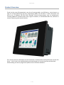
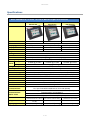
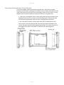
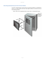
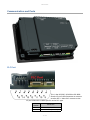
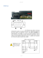
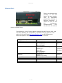
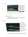
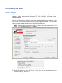
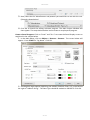
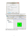
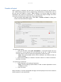
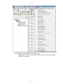
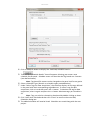
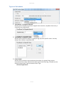
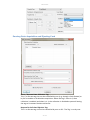
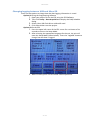
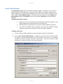
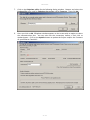
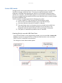
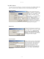
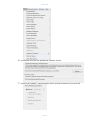
EZ3 Series
Copyright © 2015 by AVG Automation. All Rights Reserved.
EZ3 Series
Table of contents
Warnings .................................................................................................................. 3
Product Overview ....................................................................................................... 4
Specifications ............................................................................................................. 5
Installation Considerations .......................................................................................... 5
Safety Considerations ............................................................................................. 6
Installation Considerations ...................................................................................... 7
Electrical Considerations ......................................................................................... 8
Shielding from RFI ............................................................................................... 10
Installation .............................................................................................................. 12
Mounting Information ........................................................................................... 12
Powering the Unit ................................................................................................ 15
Communication and Ports ......................................................................................... 17
PLC Port .............................................................................................................. 17
COM1 Port .......................................................................................................... 19
Ethernet Port ....................................................................................................... 21
Micro SD slot ....................................................................................................... 22
USB Ports ............................................................................................................ 22
Programming the Panel ............................................................................................ 24
Create a Project ................................................................................................... 24
Transfer a Project ................................................................................................. 28
Additional Features ................................................................................................... 29
Data Logging Overview ......................................................................................... 29
Create OEM Packager ............................................................................................ 38
Create USB Loader ............................................................................................... 42
Remote Monitoring & Control ................................................................................ 44
Maintenance and Troubleshooting .............................................................................. 48
Hardware Maintenance .......................................................................................... 48
Changing the Battery ............................................................................................ 49
Update Firmware .................................................................................................. 51
Troubleshooting ................................................................................................... 53
2 / 54
EZ3 Series
Warnings
Programmable control devices such as the EZ3 Series are not fail-safe devices and as such must
not be used for stand-alone protection in any application. Unless proper safeguards are used,
unwanted start-ups could result in equipment damage or personal injury. The operator must be
made aware of this hazard and appropriate precautions must be taken.
In addition, consideration must be given to the use of an emergency stop function that is
independent of the EZ3 Series.
The diagrams and examples in this user manual are included for illustrative purposes only. The
manufacturer cannot assume responsibility or liability for actual use based on the diagrams and
examples.
Trademarks
This publication may contain references to products produced and/or offered by other companies.
The product and company names may be trademarked and are the sole property of their respective
owners. AVG Automation disclaims any proprietary interest in the marks and names of others.
Manual part number: EZ3-Touch-M
© Copyright 2014, AVG Automation
All Rights Reserved
No part of this document shall be copied, reproduced, or transmitted in any way without the prior
written consent of AVG Automation. AVG Automation retains the exclusive rights to all information
included in this document.
Designed, Built and Marketed by AVG
4140 Utica Ridge Rd. · Bettendorf, IA 52722-1327
Phone: 1-877-774-EASY · Fax: 1-877-775-EASY · flash.ezautomation.net
EU Information
The EZ3 Series is manufactured in compliance with European Union (EU) Directives and carries the
CE mark. They been tested under CE Test Standard #EN55011, and is submitted for UL
Certification.
Products with CE marks perform their required functions safely and adhere to relevant standards
as specified by EU directives provided they are used according to their intended purpose and that
the instructions in this manual are adhered to. The protection provided by the equipment may be
impaired if this equipment is not used in accordance with this manual. Only replacement parts
supplied by AVG Automation or its agents should be used.
Technical Support
Consult PLC Editor Programming Software Help. You may also find answers to your questions on
our website @ flash.ezautomation.net. If you still need assistance, please call our technical
support at 1-877-774-EASY or FAX us at 1-877-775-EASY.
SELV Circuits
All electrical circuits connected to the communications port receptacle are rated as Safety Extra
Low Voltage (SELV).
Preventative and Maintenance Cleaning
No special preventative measurement is required.
3 / 54
EZ3 Series
Product Overview
Thank You for using EZ Automation's new line of stunning HMIs - the EZ3 Series. As the latest in a
long line of high preforming and easy programming HMIs, the EZ3 Series is both convenient and
fast to use. In addition, the EZ3 Series provides several enhancements over its predecessors
including additional communication ports, higher resolution, a standard MicroSD slot, and built in
remote monitoring and control features.
This manual presents information on the installation, communication and specifications of the EZ3
Series. It also covers the troubleshooting and maintenance of an existing setup and provides
understanding on how to program the panel with our EZ Editor Software.
4 / 54
EZ3 Series
Specifications
EZ3 SERIES 6, 8 and 10-inch Model Specifications
Part Number
Specification
Enclosure
Display Type
Display View Area
Screen Pixels
Brightness/Life
Backlight
Touch Screen
Service Pow er
Operating Temp
Pow er
Backlight On
EZ3-T6C-E
EZ3-T8C-E
EZ3-T10C-E
EZ3-T6C-EH
EZ3-T8C-EH
EZ3-T10C-EH
8” TFT Color
NEMA 4, 4X (Indoor)
8” TFT (65K Colors)
10” TFT Color
10” TFT (65K Colors)
6.05”x4.55" (153.7 x 115.8mm)
8.31”x6.22" (211.07 x 158mm)
6” TFT Color
6” TFT (65K Colors)
4.65”x3.5" (118.1 x 88.9mm)
320 x 240
640 x 480
800 x 600
400 Nits/75,000 hours
White LED Strips
Analog Resistive Touch Screen
24 VDC (20-30 VDC Operating Range), 1.5A switching supply recommended
0 to 55 o C (32 to 131 o F)
15 Watts @ 24 VDC
Backlight Off
Storage Temp
Humidity
Electrical Noise
Withstand Voltage
Insulation Resistance
Vibration
Shock
# of Screens
Real Time Clock
Screen Saver
Serial/Ethernet
Communications
Serial/Ethernet
Communications
Option Cards
External Dimensions
Weight
Agency Approval
15 Watts @ 24 VDC
8 Watts @ 24 VDC
-25 to 65 o C (-13 to 149 oF)
10-95% RH, non-condensing
15 Watts @ 24 VDC
NEMA ICS 2-230 s ho w ering arc A NSI C37.90a-1974 SWC L evel C Chattering Relay Test
1000 V DC ( 1 Minute) , betw e en p o w er supply inp ut terminal an d p ro tec tiv e gro un d ( FG)
Over 20 MΩ , betw een po w er s u pply i nput termi nal and pro tective gro un d (FG)
5 to 55Hz 2G for 2 hours in the X, Y and Z axes
10 G for under 12ms in the X, Y and Z axes
Up to 999 limited by memory
Built into Panel (PLC clock is still accessible if available)
Yes, Backlight off
PLC port: RS-232/RS-422/RS-485 15-Pin D-Sub (female)
Download/Program port: RS-232/RS-422/RS-485 9-Pin D-Sub (female)
Ethernet Built-in (10/100 Base-T)
DataHighway plus / Remote IO (-EH models)
6.145”x8.048"x2.433"
(156.078x204.407x51.786mm)
8.748”x10.894"x2.289"
(222.199x276.708x58.136mm)
10.59”x13.58"x2.86
(268.99x344.93x72.64mm)
1.7 lbs
UL, cUL, CE [Pending]
2.9 lbs
3.8 lbs
UL, cUL, CE [Pending]
UL, cUL, CE [Pending]
5 / 54
EZ3 Series
Safety Considerations
Please follow all applicable local and national codes to ensure maximum safety
of the equipment and personnel. The installation and operational environment
must be maintained per the latest revision of these codes.
You are responsible to determine the codes to be followed and to verify the
compliance of equipment, installation, and operation with the latest revision of
these codes.
It is an absolute must to follow all applicable sections of:
-The National Fire Code
-The National Electrical Code (NEC)
-The National Electrical Manufacturer's Association (NEMA) codes
Safety Guidelines
Safety is the most important element of a proper system installation. Adhering
to these safety considerations ensures the safety of yourself and others, as
well as the condition of your equipment. We recommend reviewing the
following safety guidelines:
1) Disconnecting Main Power
The main power switch should be easily accessible to the operators
and maintenance personnel. It is important to make sure that all other
sources of power including pneumatic and hydraulic are de-energized
before starting the work on a machine or process controlled by the
HMI.
2) Safety Circuits
Most of the machines are installed with safety circuits such as limit
switches, emergency stop push buttons, and interlocks. These circuits
should always be hardwired directly to the EZ3 unit. These devices
must be wired in series so that when any one device opens, the unit is
automatically de-energized. This removes power to the machine. These
circuits should not be altered in any case, since this could result in
serious injury or damage to the machine.
3) Fail-Safe Operation
Our products are not fault-tolerant. They are not designed or intended
for use as online control equipment in hazardous environments
requiring fail-safe performance, such as in operation of nuclear
facilities, aircraft navigation or communication systems, air traffic
control, direct life-support machines, weapons systems, clutch control
systems on presses, in which the failure of the product could lead
directly to death, personal injury or severe physical or environmental
damage. External fail-safe and/or redundant components are required
to make your control system fail-safe.
6 / 54
EZ3 Series
Installation Considerations
Our products have been designed and tested for operation in the most
demanding industrial environments. Modern solid-state industrial controls are
complex electronic equipment that operate at low levels of voltage and current,
co-existing with components that operate at much higher levels of power. The
difference in operating power characteristics between the high and low power
control devices creates the possibility of unwanted signals being generated,
thus causing interference. The interference, which is a by-product of electrical
noise, is not present at all times. However, if it appears at random and for brief
periods of time, it can cause disruptions and errors in the operation of a control
system.
Enhancement of a system's noise level immunity and its tolerance to other
environmental hazards can be accomplished by following proper system
installation guidelines. The recommendations are of a general nature and
constitute good industrial installation practice.
General Environmental Considerations
Avoid installing the EZ3 unit in areas where the following conditions may exist:
o Environmental temperatures above or below those specified for the
EZ3 unit
o Prolonged exposure to humidity and liquids which may be sprayed or
splashed on the equipment
o Dusty environments where airborne particles may accumulate on
equipment causing reduction of heat dissipation and reduction in
effective electrical spacing between components
o Areas with excessive vibration
o Areas with high-radiated electrical noise, such as near fields of
transmitting antennas and areas in close proximity of arc welding
stations
Physical Layout in a Control Cabinet
When possible, cabinets housing electronic equipment should be designed with
provisions for natural or forced ventilation to facilitate heat dissipation.
7 / 54
EZ3 Series
Observe the following rules for cabinet installation:
o Heat
generating
equipment
(power
supplies and other
heat
inducing
components) should
be installed toward
the top of the
cabinet. The lower
space in the cabinet
is cooler than the top
area.
o Install heat-sensitive
components in the
lower section.
o Provide enough space between components to allow a free flow of
air for better heat dissipation.
o Provide the maximum possible physical separation between solid
state and electromechanical controls.
If possible, the
electromechanical controls (motors, starters, solenoids, etc.) should
be housed separately or at the farthest point when enclosed within
the cabinet.
We recommend that the unit has a minimum clear space of 2" on all
sides for adequate ventilation as shown in the image on the right.
Electrical Considerations
This section is designed to provide you with a very basic understanding of
electrical noise and how to keep it away from CPUs. Industrial plants have a
number of generators of electrical noise that are sometimes also referred to as
Radio Frequency Interference (RFI). Anytime an inductive load like a motor,
motor starter, or solenoid is turned off, it generates a burst of excess energy
that has to flow back to ground, just like electrical energy from a lightning
storm has to flow back to Earth. RFI is short bursts of electrical energy at very
high frequencies. Other sources include RF Welders or Radio Transmitters.
Effect of RFI on Electronic Automation Equipment
Electronic controls use faster and faster CPUs today. These CPUs are also
operating at 2.5V to 5VDC logic level power supply. RFI, if allowed to enter the
CPU inside, is a killer of logic. A CPU under this environment loses its brain and
behaves erratically. A smart industrial-grade CPU like the unit's card engine,
when faced with RFI, halts its operation instead of giving false outputs.
Types of RFI
RFI enters electronic controls in two ways: radiated RFI or conducted RFI. For
most practical purposes, electronic devices, unless sitting right next to a
powerful RFI transmitter, will not be affected by noise because air space
severely attenuates such interference. On the other hand, conducted RFI travels
over conductive surfaces such as power supply wires, electrical wiring of field
8 / 54
EZ3 Series
devices, and worst of all; improper ground planes.
Equipment cabinets usually incorporate one or two doors and/or hinged cabinet
panels. Relying on door hinges and swinging panels for a good metallic bond
between hinged parts and the main body of the cabinet does not insure
adequate grounding. Instead, the use of ground straps is recommended. It is
vital for the reliable operation of any electronic device to have any of its
metallic surfaces well grounded to Earth. This not only provides for safe
operation, it will also drain out any conducted RFI to Earth, away from the CPU's
signal ground.
9 / 54
EZ3 Series
Shielding from RFI
Shielded Cables
Power cables, I/O cables or wiring, and communication cables should all be
separate so that they do not couple the conducted RFI on any of these wires/
cables. Another path for RFI into the PLC is through its RS232 port. Hence, the
cables to this port must be shielded properly.
Equipment Cabinets
As mentioned, equipment cabinets typically incorporate one or two doors and/
or hinged cabinet panels. In addition, sub-panels may be utilized on those
electronic controls and electromechanical items that are mounted. The goal is
to create a medium for mounting the equipment and ensure grounding of the
control's chassis to it. However, the door hinges and swinging panels by
themselves are not enough to ensure adequate grounding.
Similarly, the equipment enclosures are generally either painted or anodized.
Mounting of painted or anodized enclosures to like surfaces also does not
ensure good metallic contact between the equipment chassis and cabinet. It is
imperative that the equipment chassis are grounded such as through the use of
grounding straps as illustrated below.
10 / 54
EZ3 Series
Cabinet Wiring
The wiring of the EZ3 unit to the “field outside the cabinet must be by design.
The wiring cannot be random in order to get the various points of the cabinet
and the “field electrically connected. Below are some general rules that apply
in most situations:
o Provide a separate power source to electronic controls and keep this
power bus away from any I/O power.
o The cabinet should be wired with a safety ground (the main safety
ground wire gauge is determined by the cabinet's total current
consumption) and in accordance with all electrical code
requirements.
o Once the cabinet doors, stationary sub-panels and swing-out subpanels have been “strappild to the main cabinet, it is not necessary
to run safety ground wires from the equipment chassis terminals to
the main safety ground connection.
o The safety ground terminal of each component can, and should be,
connected with the shortest wire possible, to the cabinet or subpanel frame.
o Plan the wiring routing. Keep all switched power in separate ducts
and if there is AC and DC power being switched, keep the wiring of
each branch separate from all wires and cables carrying low level
signals.
o Keep all three phase power outside of the cabinet, but if it becomes
necessary, keep the runs as short as possible and maintain the
maximum possible distance between the three phase bus and all
other wiring.
o Primary power leads to the control equipment (Base power
terminals) should be made with a two wire twisted cable with
approximately 12 turns per foot. The length of these cables should
be kept to a minimum, and to the greatest extent possible, such
cable runs should be kept separate from other wiring.
11 / 54
EZ3 Series
Mounting Information
Cutout Dimensions
Units: inches [millimeters]
EZ3 Panel Dimensions
Unit Size
6"
8"
10"
X
Y
8.05" [204.42mm]
6.15" [156.11mm]
Z
3.43" [87.12mm]
10.89" [276.71mm]
13.58" [345.03mm]
8.75" [222.20mm]
10.59" [269.09mm]
2.29" [58.14mm]
2.86" [72.64mm]
Panel Cutout Dimensions
Unit Size
A
6"
8"
10"
7.46" [189.48mm]
B
5.56" [141.22mm]
9.25" [234.50mm]
11.91" [302.41mm]
7.08" [179.73mm]
8.92" [226.48mm]
12 / 54
Depth
2.43" [61.72mm]
3.29" [83.57mm]
3.86" [98.04mm]
EZ3 Series
Mounting Instructions (6 Inch Model)
The 6-inch models must be mounted using DIN Clips. DIN Clips are metal
brackets (P/N EZ-BRK-1, package of 2 brackets and 4 screws) that attach to the
panel and secure the front panel to a mounting surface with 4 screws. Use the
diagram and instructions below to mount the EZ3 unit using DIN Clips.
1. There are 4 rectangular holes in each side (two at the top and two at the
bottom) of the chassis as shown in the following figure. Choose the holes
that allow the appropriate space for your mounting panel thickness.
2. On each DIN Clip there are two metal tabs (bent inward) that fit into
these holes. Insert the two clip tabs into two holes (top and bottom) and
secure the panel by alternately tightening the DIN Clip screws (4) until the
back edge of the unit's front plate is flush with the mounting panel.
13 / 54
EZ3 Series
Mounting Instructions (8 and 10 Inch Model)
The EZ3 is stud mounted. All the necessary mounting hardware is provided with
the unit. Use the 8 studs and 8 nuts with captive washers to secure the unit to
the mounting surface.
Note: Nuts are to be tightened with no more than 1 inch-pound of torque.
14 / 54
EZ3 Series
Powering the Unit
Connect the power input wires into
the HMI's power terminals. Supply
24VDC nominal (20-30VDC) power to
the system. If the unit does not
power up correctly, remove power
from the system and check all the
wiring. In addition, see the Indicator
Light
section
below
for
troubleshooting.
Status LED
LED Behavior
Status
Description
Flashes Red, then
continuously Green
Continuously Red
Normal
Operation
Unit Failure
Does Not Light
No Power
15 / 54
Suggested Response
Proceed to use unit
Return unit to factory for
service
Check or Replace 24 VDC
Power Supply - if condition
continues return unit to factory
EZ3 Series
for service
16 / 54
EZ3 Series
Communication and Ports
PLC Port
This is the RS-232C, RS-422A or RS-485A
female 15-pin D-Sub Connector to connect
to other PLCs. Most PLCs connect to the
15-pin D-Sub with a cable specific to the PLC type.
Pin
Number
1
2
Connection
Chassis GND
PLC TXD (RS-232C)
17 / 54
EZ3 Series
3
4
5
6
7
8
9
10
11
12
13
14
15
PLC RXD (RS-232C)
+5V (100W )
Logic GND
LE
PLC CTS (RS-232C)
PLC RTS (RS-232C)
RXD+ (RS-422A)
RXD- (RS-422A)
TXD+ (RS-422A)
TXD- (RS-422A)
Terminating Resistor
(connect to pin 9)
NC
NC
18 / 54
EZ3 Series
COM1 Port
The EZ3 Series has a built-in serial port
(COM1 PORT) located on the 9-pin D-Sub connector. COM1 PORT is an RS-232
port which requires an appropriate RS-232C cable (P/N: EZ-PGMCBL) for
programming the unit through a PC. It serves as the default programming port
on the EZ3 Series. Since COM1 has fixed communication parameters, you can
always connect the programming software to the PLC through the port without
needing to make different configuration changes. In addition, this connection
can be utilized to update firmware when needed.
19 / 54
EZ3 Series
20 / 54
EZ3 Series
Ethernet Port
There is an Ethernet port
available on the EZ3
Series. This port enables
users to add/update
programming through an
Ethernet connection. It
allows for both PC and
PLC
simultaneous
communications. It can
also be used for Internet
access and email alerts.
The following is a list of current drivers supported by the EZ3 Series units. We
are always updating PLC compatibility, if you don't see your type PLC in this
table, visit our web site at flash.ezautomation.net/ or call EZAutomation
technical support at 1-877-774-3259 or FAX at 1-877-775-3279.
PLC Manufacturer
AVG/EZAutomation
Allen Bradley
KOYO (AutomationDirect)
Modicon
Mitsubishi
Omron
GE
Siemens
21 / 54
Serial Drivers
EZPLC
DH485/AIC/AIC+
DF1 Half Duplex
DF1 Full Duplex
Modbus (Koyo addressing)
Modbus RTU
Direct NET
ADC K-Sequence
Do More Serial
Modbus RTU
Modbus Uni-Telway
Mitsubishi FX
Host link adapter
GE SNP-X
S7
Ethernet
EZ Ethern
Ethernet/
DF1 over
Modbus T
ECOM Eth
Do More E
Modbus T
GE SRTP
Siemens I
EZ3 Series
Micro SD slot
A Micro SD slot is available
to allow for additional
storage or data transfer.
Insert a Micro SD into the
slot and it will load
automatically. Additional
details about using a
MicroSD Card for data
logging is available in the
Data Logging Overview
section. When finished, push against the Micro SD card to eject it from the
unit.
Note: Please do not use Micro SD and USB drive to log data
simultaneously.
Network Option Cards
Depending on model purchased, a network option card is also available for
additional connectivity. EZ3 Series units ending in -EH come equipped with a
DataHighway Plus / Remote IO option card.
USB Ports
Dual USB Ports
EZ3 Series HMIs come
equipped with two USB
ports. The port on the left
is for program upload
through a USB A to USB B
programming cable.
Note: If a powercycle
occurs while the USB
programming
cable
is
connected, the cable will
need unplugged and then
replugged in to reestablish a
connection.
The Host USB port (on the right) can connect to a USB Flash drive for program
upload by simply using our EZ Editor Software to create a USB Loader file (.hmi).
22 / 54
EZ3 Series
This process benefits system integrators and OEMs by permitting them to
upgrade panels on site without the need to connect to a computer. Please see
our EZ Editor Software Help for detailed instructions on this process. In
addition, the Host USB can be utilized for data logging purposes in combination
with our AVG Remote File Manager Utility.
Note: Please do not use Micro SD and USB drive to log data simultaneously.
23 / 54
EZ3 Series
Programming the Panel
Create a Project
This section outlines the basics of creating a project using the EZSeries Editor
software. Further programming information for the EZ3 Series is located in the
Software Manual.
Launch your Programming Software and select how you would like the program to link
to the EZ3. For this scenario, you can select 'Edit Program OFF-LINE.' This will enable
you to create a program without having the EZ3 unit connected.
NOTE: EZ Series Editor must be version 6.1.11 or later to communicate with the EZ3
Series. Unit firmware must be k.5.35 or later.
1.
Enter a project name (e.g. Test). Click OK.
2.
Under Panel Family, select EZ3 Series. Then select the size appropriate for your
purchased unit (6", 8" or 10").
24 / 54
EZ3 Series
3.
Next, select the PLC Manufacturer and protocol you would like to use with the unit.
(Example shown below.)
4.
Click OK to launch the editing software program. The Main Project Window will
then appear. The steps below outline how to create a sample panel program.
Create a Panel Program: Click on “Panied and "Scr 1" to create the Panel display screen as
explained in the sample below.
1. In the Main Menu, click on Objects > Buttons > Buttons. The screen below will
appear. Enter START for Tag Name. Click OK.
2. A dialog box might appear requesting the memory location. Enter "S1" in the field to
the right of "Address String." The Data Type should be marked as DISCRETE. Click OK.
25 / 54
EZ3 Series
3. Click anywhere on the screen to place the Button object. Double click the icon to
open its object dialog box if you need to adjust the object's appearance or attributes.
Clicking "Simulates Press" will allow you to toggle between On and Off states.
4. Similarly, you can create an Indicator Light Object by selecting Objects > Data
Display > Indicator Light. Enter Lamp for Tag Name. Click OK. Place the object on the
panel. Your screen should look like the picture below.
26 / 54
EZ3 Series
27 / 54
EZ3 Series
Transfer a Project
After a project is complete, the next step is to transfer the project to the EZ3 Series
unit. When editing projects online, programming information is automatically sent to
the unit once the project is saved. When editing in an off-line mode, the project
information will need to be transferred. To transfer the project through the serial
connection or Ethernet port, follow the steps outlined below:
From the Project drop down menu, select File > Transfer to Panel. A dialog box
similar to the one below will appear.
If transferring serially:
1. Verify the RS-232C cable (P/N: EZ-PGMCBL) is connected between the unit
and the PC. In the absence of an RS-232 port on the PC, a USB to RS-232
converter may be used to connect the programming cable to the PC.
Note: The recommended USB to Serial converters are ATEN-UC-232A or
Belkin-F5U409.
2. Select Serial (COM1) as method of transfer under PC to Panel Connection.
And then click Start.
If transferring via Ethernet:
1. Select Ethernet as PC to Panel Connection.
Note: Click the Specify IP/Port button in order to make adjustments to the
IP Address or Port.
2. Then click Start.
When finished, a Transfer Completed message will be displayed. Click OK to continue
and the project is now transferred.
28 / 54
EZ3 Series
Additional Features
Data Logging Overview
The EZ3 offers a flexible Data Acquisition capability. You can acquire and save the data
for one or more tags defined in the panel. The acquired data along with a time stamp is
saved in CSV file format in the USB stick or the MicroSD card, depending on how the
schedule is set.
Schedules determine the way data will be collected. For example, data can be collected
every 10 seconds, or simply at a specific time such as 9 AM, or when a certain event
takes place. The user can define one or more schedules as long as each schedule is
unique. (For example, there cannot be two schedules that each collect data every 30
seconds.) User can also associate a name (up to 8 characters) with each schedule.
Each schedule can be used to collect data for up to 32 tags.
Adding a Schedule
1. Open your project file for the EZ3 using the EZ Series Software.
2. Then click Setup > Data Acquisition to display the DAQ Schedule dialog.
29 / 54
EZ3 Series
3. The Data Acquisition dialog box will appear. This dialog box allows you to add the
new schedules and edit/delete the existing ones.
Please note: User must select either USB or Micro SD as a data-logging
option (shown below).
30 / 54
EZ3 Series
4. Click on Add/Elit buttn tt lispeaa tti ““ll “A Stiluei itaies.d
5. The "Add DAQ Schedule Details" box will appears allowing you create a new
6.
7.
8.
9.
schedule for the panel. Schedule names can be either be Tag based or a Constant
(user defined name).
Note: Tag based file names can be changed on the panel itself at any point.
Select a Schedule Type. (Details on schedule types provided below.)
Under "Select Tags for Data Acquisition," the selection displays all the tags defined
in the panel with their corresponding tag addresses. To select a tag for data
acquisition, click on it and then press the >> button. To deselect the tag for data
acquisition, select it again and press the << button. Maximum tags per schedule is
32.
Note: Tags can also be selected or deselected by double-clicking on them.
Click "Add" when finished and then click "Close" to return to the main DAQ
Schedules dialog box.
The added schedules will now be listed. Schedules are saved along with the user
project.
31 / 54
EZ3 Series
Types of Schedules
1. Time based – at regular Intervals
Allows you to store the tag value at regular time intervals, anywhere from every 1
second to every 1000 hours.
2. Time based – at Specifc Times
Allows you to store the value of a group of tags up to 10 specific times. You may
always edit / delete a specified time.
3. Event Based:
Allows you to create an event and store the values of a group of tags on the
occurrence of the same. Based on the data type of the event tag, schedule can be
either Discrete Event Type or Numeric Event Type.
Discrete Type Event:
32 / 54
EZ3 Series
33 / 54
EZ3 Series
Numeric Type event:
4. Event Based - at Regular Intervals:
Allows you to create an event and store the values of a group of tags on the
occurrence of the same during a set time period. Based on the data type of the
event tag, schedule can be either Discrete Event Type or Numeric Event Type.
a. Set how frequently the data is stored through the Time Based interval,
anywhere from every 1 second to every 1000 hours.
b. Select either a Discrete Type Event or a Numeric Event Type.
Discrete Type Event:
Numeric Type event:
34 / 54
EZ3 Series
Pausing Data Acquisition and Ejecting Card
Pause / Resume Data Collection Tag:
This is a discrete tag that can be controlled by user (e.g. through a Push Button) or
by PLC to enable or disable data acquisition. When the tag's value is 0, data
collection is enabled; and when it is 1, the collection is disabled or paused. Setting
the tag to 0 resumes the data collection.
Request for Safe Card Ejection Tag:
This is a discrete tag and can be controlled by user or PLC. The Tag is set by user
35 / 54
EZ3 Series
(say by a Pushbutton) or by PLC to indicate that the user would like to remove the
SD card for possibly reading it in a SD card reader. When Panel sees this tag as set,
all buffered data is written to the files, and files are closed for safe removal of the
card. Another discrete tag, Safe-to-Eject-Card is set to indicate that it is now safe to
remove the SD card without fear of file corruption. At the same time, the Request
tag is reset by the panel.
Safe to Eject Card Tag:
This is a discrete internal tag. The tag must not be mapped to PLC. The Panel would
set this tag when it is safe to remove the card. It is reset whenever it is unsafe to
remove the card. It is highly recommended that you use Request-for-Safe-CardEjection and Safe-to-Eject-Card tags for removing the card. If the card is
removed without safe indication, the data on the card may get corrupted due
to open files.
36 / 54
EZ3 Series
Changing logging between USB and Micro SD
There are two options to change how the data logging information is saved.
Option #1 Using the Programming Software
1. Open your project file for the EZ3 using the EZ3 Software.
2. Then click Setup > Data Acquisition to display the DAQ Schedule
dialog.
3. Select either USB Flash Drive or MicroSD card.
4. Click OK and then save the project.
Option #2 On the EZ3
1. Press the upper left corner of the EZ3 screen for a minimum of six
seconds to access the Setup Mode.
2. After selecting the appropriate language for the unit, the unit will
enter the Setup Mode (shown below). Press the "LogtoSD" button to
change how the data is logged.
3. When finished, press Exit to resume normal operations.
37 / 54
EZ3 Series
Create OEM Packager
The EZPackager utility allows an OEM to distribute updates to EZSeries Touch Panel or
EZPLC projects easily and quickly. Using the utility, OEMs can package current project
and/or firmware into a zip file for distribution to the end user via email or the web. If you
click on File > Create OEM Package, it will allow you to package the current EZPanel or
EZPLC project and/or the firmware into a zip file called a pack file for the distribution
purposes.
Benefits of the utility include:
•
•
•
OEMs save costs associated with the distribution of panel updates in the
field (sending field service personnel or mailing CDs).
OEM Projects are protected since end users cannot modify the projects.
The end user benefits from convenient, fast and easy updates without
needing to purchase the EZSeries Touch Panel Editor software.
Creating a Pack File:
1.
Use the EZ Series Editor Software to open the project you wish to distribute.
2.
Click on File > Create OEM Package. A dialog box similar to the one shown below
will appear. Select what firmware you wish to include in the zip file. (Use Browse
to locate the latest firmware versions if necessary.) Enter any necessary OEM
information you wish to include in the fields provided.
38 / 54
EZ3 Series
3.
Use Browse to determine the file save location and OEM package name. Then
click OK.
39 / 54
EZ3 Series
Opening a Pack File
A Pack File contains the following:
1. Updater application (comprising of the .exe and required dlls)
2. Project files (which would show up inside the Project folder when unzipped)
3. Firmware files (which would show up inside the Firmware folder when unzipped
The end user can take the pack file, unzip it, and then run the EZSeries Touch Panel Updater
application to update his/her panel with the selected project(s) and/or firmware. To open a
pack file, follow the steps below:
1. Click on the zipped OEM Package file that you have. It contains EzUpdate.exe (Ezupdater
MFC application) and example.pkg (PKG File). Extract these file in a folder of your
choice.
2. In this example, files have been extracted in a folder named as example_OEM Package.
40 / 54
EZ3 Series
3. Click on the EzUpdate utility for the following dialog window. Browse and select the
Package File to be used for updating the project and/or firmware. Then click OK.
4. Once you click on OK, EZUpdater window appears on the screen with an option to select
the communication port. You may also test the connection, before a final click to
Update button. Click on the Update button to update the Project and/or the Firmware
on your EZSeries TouchPLC.
41 / 54
EZ3 Series
Create USB Loader
Through the EZ Series Editor Software (version 5.5 and higher) users can program EZ
TouchPLCs through a USB Flash drive. This process especially benefits System
Integrators and OEMs with upgrading the Panels on-site without having to actually
connect to a computer. Since multiple programs can be saved on one USB Flash drive,
the user can program different panels with the same USB Flash drive, or quickly change
the Panel for different jobs.
The EZ TouchPLCs can be programmed in following easy steps:
1. Create a USB file (*.hmi) using the EZ Touch Program Loader.
2. Save the file on the USB Flash drive (only in the root directory).
3. Insert the USB stick into the EZ TouchPLC's USB port.
4. The panel brings up a list of projects that are available on the USB Flash
drive. Select the necessary project and press OK. (If the panel is not
compatible with the project selected, an Error message is displayed.)
5. The project is automatically loaded on the EZ TouchPLC.
Creating files for use with USB Flash Drive
In the EZ Series Editor's main programming window, click on menu File > Create USB
Loader to create user project file for use with the USB flash drive. User can select
name. The file is saved with .hmi extension.
The dialog box shown below would appear:
42 / 54
EZ3 Series
Copy file(s) on USB Drive
Copy file(s) created by the editor on the root directory of a USB flash disk.
(Please note files copied in a location other than root directory would not be
read by the panel.) All files are saved automatically with .hmi extension. Files
without this extension will not be read.
Programming the panel using USB Drive
To program an EZ TouchPLC from USB Drive, insert the USB flash directly into
the EZ TouchPLC's USB port. The panel would display a list of files available in
the root directory (with .hmi extension). An example is shown below:
Select the required project using the Up- twn arrtws anl priss ““SSipt.d If tti
panel is not compatible with the project selected, an Error message saying
“Wrtng panie Tapid is lispeaail. The selected project is then automatically
loaded into the EZ TouchPLC.
43 / 54
EZ3 Series
Remote Monitoring & Control
With the introduction of new Remote-Access Card and Remote Monitor & Control
(RMC) Software EZSeries TouchPLCs offer a unique set of remote capabilities. A user
can remotely log on to a unit and monitor any of the panel screens with live data
including the currently displayed screen.
With the right access permissions and authentication, a usir San rimttiea “ttuStd tti
objects on the panel, to control a machine/plant effectively. Remote control feature
can be invaluable for remote diagnostics, unmanned operations, or supervisory
monitoring.
In addition to remote monitoring and control, user may also program the panels
remotely over Ethernet, allowing OEMs to remotely upgrade the screen programs
within the panels.
For Remote Monitoring and control we need to follow these steps:
1. Use EZ Touch Panel editor to set up IP address of the panel.
2. Use EZ Touch Panel editor to set up remote users and authentication level.
3. Use RMC (Remote Monitoring & Control) software to connect to the panel
remotely.
Setting up Remote Users
The EZ-RMC Software can be used with or without defining authorized users. If you
don't define any remote users, then anyone can connect to the panel using EZ-RMC
Software. However they can ONLY VIEW the panel screen; they would not be able to
make any changes to the panel. It is highly recommended that you do define
authorized users for remote access.
Remote users can be given View ONLY or Operation (View + Control) permission.
View only permission allows user to ONLY monitor the panel display remotely, while
operation permission allows a user to operate panel remotely.
Select Remote Access > Remote Users as shown below to display the following EZRMC User Dialog window
44 / 54
EZ3 Series
Set Remote Users
Here you may
add up to 8
remote users
by clicking on
Add/Edit
button. The
Log-in name
and the
password are
case sensitive
and both must
be between 8
to 16
characters in length. Password also must contain at least one letter and one number.
Add/Edit Remote Users
To edit the
information of an
existing user,
please select the
appropriate row
and click on Add/
Edit button. It
will bring up the
information of
the selected user
in edit mode.
·
·
Access Level
ONLY Remote VIEW - A user can remotely log on to the panel and monitor
any of the panel screens with live data including the currently displayed
screen.
Remote OPERATION - A user can remotely log on to the panel and monitor
any of the panel screens with live data including the currently displayed
sSriin as wiee as San rimttiea “ttuStd tti tbjiSts tn tti panie, to
effectively operate or control a machine/plant.
45 / 54
EZ3 Series
WARNING!!!
Be VERY selective and careful in allowing users remote operation access. Users
MUST take extreme care during remote operation. It is highly recommended that
panel/machine be watched by someone during its remote operation, as remote
changes can be dangerous and can cause accident or damage to machine!!!
46 / 54
EZ3 Series
Run RMC Software
To access the panel over Ethernet, you need to install and run the EZ-RMC software on
your PC. Once you run the software, you will see the following EZ-RMC dialog.
Select Parameters
Select the communication port, IP
Address if Ethernet is selected, and
Polling Time. The IP Address is the
IP Address of the RMC card you
setup earlier. It is recommended to
keep polling time as high as
possible. Polling time determines
how often RMC software would
read information from the panel. A
lower polling time may impact the
performance of the panel.
Remote User
Clicking OK will prompt you to provide user
name and password, if at least one remote
user has been set up. Please note that
both user name and passwords are case
sensitive. If no remote users were defined,
this dialog box would not appear.
Access Password
Projects requiring an Access Password will
need the access password entered before
the user information. You must have a
correct Access Password in order to
communicate with the panel. This is
project level password set during screen
design under Setup > Panel Attribute >
General Tab.
47 / 54
EZ3 Series
Maintenance and Troubleshooting
Hardware Maintenance
Routine maintenance checks should be performed on the unit to avoid any risk of
hardware problems. The EZ3 Seriesis designed to be a very rugged controller so
that just a few checks periodically will help keep it up and running.
The key points to be checked include:
· Ambient operating conditions
· Wiring and connections
Maintaining the Ambient Operating Conditions
Keeping the EZ3 Series unit's environment within specified operating conditions is
the best method to minimize the maintenance.
1. Always ensure that ambient temperature inside the cabinet is within EZ3
Series unit's temperature ratings.
2. If any other equipment inside or outside of the cabinet is producing heat,
employ cooling methods like a blower fan to reduce 'hot spots' around the EZ3
Series.
3. Periodically inspect and clean if there are any air filters on the cabinet.
Ensure that the unit is free from dust, humidity and corrosive gases.
48 / 54
EZ3 Series
Changing the Battery
The unit comes with a built in Lithium battery with a 5 year life expectancy. The
steps below outline the process to change the battery inside the unit. Since
only the information saved to the registers/discretes available on a power cycle
will remain intact, please save pertinent information before attempting to
change the battery. Then remove power from the unit.
1. Open the back cover to access the battery.
2. The battery is located in the upper-left hand corner as shown in the
figure below. Remove the old battery and replace with a new 1/2
AA, 3.6 V Lithium Battery (Part Number: EZ-BAT).
3. Close rear cover and ensure that the door latches.
4. Reconnect power source. Connect to PC and run the Programming
Software to transfer back the user program to the EZ3 Series.
49 / 54
EZ3 Series
The Real Time Clock (RTC) will need reset after the battery has been replaced.
All information saved to the registers/discretes available on a power cycle will
remain intact. Data not saved to registers/discretes available during a power
cycle will be lost.
50 / 54
EZ3 Series
Update Firmware
1
2
Insert a RS-232C cable into the COM1 port and launch the EZ Panel Editor software.
Select Edit Program ON-LINE and enter a project name (e.g. Test). Click OK.
3
Under Panel Family, select EZ3 Series. Then select the size appropriate for your
purchased unit (6", 8" or 10").
4
Next, select the PLC Manufacturer and protocol you would like to use with the unit.
(Example shown below.) Then click OK.
5
After the project loads, click Set-up > Upgrade Firmware. A dialog box will appear
requesting the firmware file you would like to load to the unit.
51 / 54
EZ3 Series
6
Use Browse to locate the appropriate firmware version.
7
Verify Serial (COM1) is selected under the PC to Panel Connection, then click OK.
52 / 54
EZ3 Series
Troubleshooting
If you encounter difficulties while using our EZ3 Series device, please consult the table below.
Additional assistance is also available within the EZ Panel Enhanced Software Help.
Alternatively, you may also find answers to your questions in the operator interface section of our
website @ flash.ezautomation.net.
Problem
Operation
Status LED
is off
Possible Cause
Suggested Action
Disconnected or
faulty power source
Check and repair power source.
Check the wiring for loose conta
secure them if found.
Ensure that proper polarity is obs
Status LED is red
Input power level is
outside of unit's
power rating
specifications
Ensure that the power being pres
the PLC terminal is within the sp
range.
Unit Failure
Power cycle the PLC once to see
intermittent high frequency noise
caused the failure.
If problem persists, call AVG Aut
assistance.
Communication
No communication with Disconnected or
unit
loose cable
Check the wiring for loose conta
secure them if found.
Ensure you are using a correct
communication cable.
No communication with Wrong/broken cable
the PC (RS232 Port
error)
Still Need Help?
Technical Support
53 / 54
Ensure the correct communicatio
being used (PGMCBL).
Wrong
communication port
settings
Check and correct the COM port
Wrong COM port
assignment on the
computer
Check if correct Serial Port (COM
computer has been selected.
EZ3 Series
Most of the frequently encountered problems regarding the EZ3 Series unit's
operation are answered in the sections above. However, if you still need answers to
your questions, please call our technical support at 1-877-774-EASY.
Warranty Repairs
If your EZ3 Series is under warranty, contact us at 1-877-774-EASY.
Out of Warranty Services
If your EZ3 Series is out of warranty, contact EZ Automation at 1-877-774-EASY for
an evaluation of repair costs. You can then decide whether it is more economical to
proceed with the repairs or to upgrade your system with a new unit.
54 / 54