1
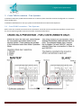
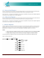
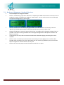
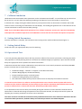
HAWK GLADIATOR MICROWAVE “COLLISION PREVENTION SWITCHES” SET UP PROCEDURE 1 Introduction Hawk Gladiator Microwave Switches can be used to detect & indicate a possible collision and therefore prevent boom collisions of large machinery. Microwave switches are typically placed longitudinally on each side of the boom and when required on each side of the counterweight. The Microwave Sender unit pulses microwave energy to the receiver (approx 200 pulses per second) and if the beam is broken the Hawk Microwave Switch indicates a possible collision via relay for machine movement to be halted by the machine control system. Microwave Switches have anti crosstalking connection & setup options for two or more systems present on a single machine. For two systems one unit is set to ‘Master’ mode and the other to ‘Slave’. The ‘Master’ unit controls the pulsing for both systems. For more than 2 systems a Hawk Microwave Sequencer unit should be used. In this case the Sequencer acts as the ‘Master’, and all connected Microwave systems are programmed as ‘Slaves’ There are various stages of commissioning that shall be performed in the following order: Mounting Location Check Cross Talk Prevention Wiring and Device Configuration Visual alignment Software Alignment Final Calibration Collision Simulation Setting Switch Parameters (do not set the switch value until after alignment, this may create a CAL Error) Setting of Switch Delays Operational Test Thursday, 12 May 2011 Page 1 2 Mounting Location Check Note the recommended mounting locations for the Sender & Receiver pairs – each parallel & back to back system faces the opposite direction. The Microwave should ideally have a 2 meter exclusion zone around a straight line between the Sender and Receiver. Over distance the beam will spread and bounce off metallic objects. The Sender & Receiver should be mounted on secure & stable arm which extends outside & below the boom or counter weight ideally to a length of 3 meters. The arm must be completely stable. The slightest shift will adjust the beam angle increasing the likelihood of nuisance trips. Hawk recommends MA15 extension tubes for each sensor. The tubes reduce beam spread making alignment more accurate & deflect false pulses. You should establish the suitable placement of the mounting arms & sensors prior to commissioning. Thursday, 12 May 2011 Page 2 3 Cross Talk Prevention – Two Systems Installations with Two (2) Microwave Switches on a common plane should be wired and configured as in a Master – Slave configuration. Installations with More than Two (2) systems should be wired into a Microwave Sequencer. 3.1 Cross Talk Prevention – Two Systems Refer to the user manual to ensure that the instruments are wired correctly and that the amplifiers are each set to the correct operating mode to prevent Crosstalk. Overview shown below. Thursday, 12 May 2011 Page 3 3.2 Cross Talk Prevention – More than Two Systems Installations with More than Two (2) Microwave Switches (2 switches mounted on the Boom and 2 Switches mounted on the Counterweight) shall be wired into a Microwave Sequencer in accordance with the User Manual. Refer to the user manual to ensure that the instruments are wired correctly and that the amplifiers are each set to the correct operating mode (Slave). The Sequencer unit acts as the Master. Thursday, 12 May 2011 Page 4 4 Visual Alignment It is critical that the installation provides the ability to move the sender and receiver up BOTH and down and left to right. If there is no mechanism on the mounting brackets to mechanically alter the alignment of a Microwave Sender and Receiver in BOTH planes then inserting Stainless Steel washers behind the square flange of the Sender or Receiver will be necessary. The alignment procedure below will require Two (2) persons and the use of an Elevated Working Platform (WEP) will greatly assist with both the visual and software the alignment procedures. The use of a Two Way Radio will greatly reduce the time required to align the microwave switches. Thursday, 12 May 2011 Page 5 4.1 Receiver Visual Alignment Person A is positioned near the sender and visually looking towards the remote/distant Receiver whilst Person B moves the Receiver both vertically and horizontally until the receiver is pointing at the sender. Please note that +/- 10 Degrees of misalignment at this stage is acceptable at this point as the software alignment will be used at a later stage for more accurate alignment. 4.2 Sender Visual Alignment Person A is positioned near the Receiver and visually looking towards the Sender/distant Receiver whilst Person B moves the Sender both horizontally and vertically until the receiver is pointing at the sender. Please note that +/- 10 Degrees of misalignment at this stage is acceptable at this point as the software alignment will be used at a later stage for more accurate alignment. 5 Software Alignment Software alignment is simply the movement of the sender/or receiver left/right & up/down by one person whilst another person watches the Sensor Value or Signal Voltage on the amplifier LCD display. The Sensor Value will decrease when the alignment is improved. The Voltage Signal will increase as alignment is improved. NOTES: Software alignment CAN ONLY be performed when the Amplifier has been set into Alignment Mode. DO NOT attempt to align the devices without first setting the amplifier into Alignment Mode. To set the Amplifier into alignment mode see the below software flow chart & follow the alignment steps. Figure 1: Software Flow Chart Thursday, 12 May 2011 Page 6 5.1 Hardware Alignment – Sender & Receiver 1 2 Set the Amplifier into Alignment Mode Perform “Cal Mounting” operation. When this is complete press RUN several times to return the unit to standard run mode. The default run display is ‘Switch Value’. You can use the arrows to scroll through the operational diagnostics to find ‘Signal’. 3 After the Cal Mount the unit will display approx 48%. Scroll with the down arrow and you will see ‘Signal 1.20V’ (value approximately 1.20V) along with the Sensor Value on the 2nd line. The goal of alignment is to get the Sensor Value as low as possible and/or the Signal Voltage as high as possible. If the Sensor Value gets below 20% or the Signal Voltage above 2.00V perform another ‘Cal Mount’ and return. If required use two way radio to communicate between individuals aligning & watching the control amplifier. The first action is to slowly move the Receiver horizontally (Left to the Right) until it reads the best possible value according to the above. Next adjust the unit vertically (up & down) until you locate the optimum alignment. Lock the Receiver unit in place Perform the same step sequence with the Sender unit & lock it in place. 4 5 6 7 Thursday, 12 May 2011 Page 7 6 Final Calibration Change the Amplifier from “Alignment” Mode into “Boom Protection” Mode and then perform a “Calibrate Mounting (see Figure 1: Software Flow Chart). Return the unit to normal run mode. After calibration, the ideal Sensor Value % should display less than 10% and the ideal Signal Voltage is greater than 2V. Use the arrow buttons to scroll through these diagnostics during normal run mode. If you cannot attain either of these after final calibration repeat steps 5.1 & 6. If you still cannot attain either value check the Gain diagnostic (using arrows in run mode). If this value is over approximately 85% (94.2% possible max) then the unit is struggling to successfully Calibrate with the current mounting conditions (including alignment & obstacles creating reflected echoes). If you are unable to proceed past this point contact Hawk technical support with photos of the application set up for assistance. Thursday, 12 May 2011 Page 8 7 Collision Simulation Hawk Microwave Device Switch Point parameter can be set between 0 and 100%. To avoid false trips this should not be set too low. You can check the switching by placing a steel plate in front of the sender or receiver unit. A collision test is simply moving the mobile machinery into a position where an obstruction is between the sender and the receiver and noting the % Blocked on the LCD Display. This reading will guide the user in the selection of the correct switch Point as well as the time delay settings. NOTE: If your client WILL NOT provide permission for a collision simulation, contact your supervisor immediately and explain that a Collision Supervision test if CRITICAL to ensure that the instruments will operate as required! 8 Setting Switch Parameters Once the simulation is complete, the final Switch Point setting can be confirmed & entered (see Figure 1) 9 Setting Switch Delay Confirm & enter your appropriate delay time for switching. 10 Operational Test A correctly operating Microwave Switch will only prevent a collision if the control system that is watching the switch relay operation is actually working and has no software or hardware bridges (or bypasses) in place and the selected delays are appropriate for the speed of the machine movement. A Microwave Switch that has been calibrated correctly and has the correct switch parameters and delays MAY NOT prevent a collision due to various factors including: Hardwired “Bridge”, “Isolation” or “Bypass” of the Microwave Relay Software Bridge (Bypass) of Microwave Relay Excessive Software Delays in Control System Insufficient braking/slowing of the machine Poor Placement of Microwave prevents sufficient time to slow/stop the machine movement It is therefore critical that a Live Collision Test be performed to ensure that the Control System will slow the movement of the machine sufficiently and eventually stop the machine movement with sufficient time actually prevent a collision when an obstruction has been detected by the Microwave Switch. A Live Operational Test involves slowly and carefully driving the machine in various directions towards obvious obstructions or hazards and testing the operation of the microwave switches, the delays and control system and adjusting any necessary parameters to ensure correct operation. The client must then calculate the maximum velocity and deceleration times of the machine to determine that the microwave switch parameters, hardware delays and software parameters are indeed adequate. Thursday, 12 May 2011 Page 9