1
2 Mounting Location Check
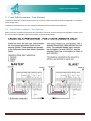
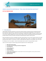
Note the recommended mounting locations for the Sender & Receiver pairs – each parallel & back to back system
faces the opposite direction.
The Microwave should ideally have a 2 meter exclusion zone around a straight line between the Sender and
Receiver. Over distance the beam will spread and bounce off metallic objects.
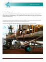
The Sender & Receiver should be mounted on secure & stable arm which extends outside & below the boom or
counter weight ideally to a length of 3 meters. The arm must be completely stable. The slightest shift will adjust the
beam angle increasing the likelihood of nuisance trips.
Hawk recommends MA15 extension tubes for each sensor. The tubes reduce beam spread making alignment more
accurate & deflect false pulses.
You should establish the suitable placement of the mounting arms & sensors prior to commissioning.
Thursday, 12 May 2011
Page 2