1
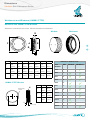
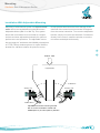
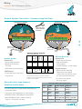
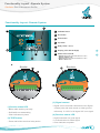
Sultan Sonar Manual Rev 1.0 A Higher Level of Performance Manual Gladiator Gen 3 Microwave Switch Series Beam Blockage Detection Circular Polarisation For more information, please visit > www.hawkmeasure.com > Table of Contents Gladiator Gen 3 Microwave Series Contents Overview 3 Setup Procedure - Integral System 19 Principle of Operation Typical Uses Function Features 3 3 3 3 Setup Procedure - Remote System 20 Operational Diagnostics 21 Dimensions 4 Remote Main Menus & Interface 22 Remote Microwave System Weldments and Windows (UHMW / PTFE) Weldments and Windows (Ceramic) Weldments and Windows (Ceramic Tile & Firebrick Assemblies) 4 5 6 Mounting 9 7 General Guidelines Mounting With Windowed Weldments Installation With Adjustable Mounting Correct Mounting Angle Align Sender and Receiver 9 10 11 12 12 Wiring 13 Remote System Connection HAWK Supplied Cable Remote System Connection Customer Supplied Cable Alternate cable type between Amplifier and Sensors 22 Remote Setup Procedure 23 Quickset Menu - Parameters App Type - Parameters Advanced Menu - Parameters 23 24 25 Relay 2 Actions 26 > Relay 2 Software Flow Chart 27 < Cross-Talk Prevention / Sequencer Wiring 28 Integral Test Switch 29 Integral Receiver Test Switch Functions 29 13 Troubleshooting 30 14 Error Codes 31 Safety Information 32 FCC Regulations 32 Part Numbering 33 Remote Version Integral Version 33 34 Specifications 35 14 Functionality Layout - Remote System 15 Wiring 16 Integral System Connection 16 Functionality Layout - Integral System 17 Wiring 18 Wiring - Relay Functions 18 PROPRIETARY NOTICE The information contained in this publication is derived in part from proprietary and patent data. This information has been prepared for the express purpose of assisting operating and maintenance personnel in the efficient use of the instrument described herein. Publication of this information does not convey any rights to use or reproduce it, or to use for any purpose other than in connection with the installation, operation and maintenance of the equipment described herein WARNING This instrument contains electronic components that are susceptible to damage by static electricity. Proper handling procedures must be observed during the removal, installation, or handling of internal circuit boards or devices: 2 Remote Main Menus & Interface - Remote System Handling Procedure: 1. Power to unit must be removed prior to commencement of any work. 2. Personnel must be grounded, via wrist strap or other safe, suitable means, before any printed circuit board or other internal devices are installed, removed or adjusted. 3. Printed circuit boards must be transported in a conductive bag or other conductive container. Boards must not be removed from protective container until the immediate time of installation. Removed boards must be placed immediately in a protective container for transport, storage, or return to factory. Overview Gladiator Gen 3 Microwave Series Principle of Operation Beam blockage A beam of microwave energy passes from a sender to a separate receiver in bursts approximately 200 times per second. If the path between the sender and receiver is blocked by any object or material which absorbs or reflects microwave energy, then the receiver will not be able to detect the signal. The presence or absence of the signal at the receiver is used to switch a relay for indication or control purposes. Microwaves are small (Micro) radio waves transmitted from point to point hence the system setup of ‘sender’ and ‘receiver’ units. > Typical Uses < • Blocked chute detection • Nucleonic switch replacement • Collision detection • High level alarm / Low level alarm • Stacker / Reclaimer protection • Truck / machine detection. • Shiploader protection Function The Gladiator Microwave Switch can be used for blockage detection, barrier detection, machine detection, collision detection for protection, point level measurement, and detection of objects or material between two points. Features • State of the art Circular transmission • Relay outputs: Integral (1 + failsafe) Remote (2) • Backwards compatible with all Gladiator Microwave • Remote test function generations • Adjustable ON and OFF delays (0-20 sec) • LCD push button setup / diagnostics on • Remote 3G HAWKlink connection option remote amplifier • Remote amplifier to sensor separation up to • Simple sensitivity adjustment and calibration on 500 meters (1640ft) Integral system • Bright visual status indication on sensors • Ranges up to 1200 meters (3937ft) • Independent housing alignment after mounting • Simple ‘1-minute’ setup application pre-sets sensor. • Remote sensor or Integral ‘all in one’ types 3 Dimensions Gladiator Gen 3 Microwave Series Remote Microwave System Remote Amplifier 30.7 mm (1.2”) 78 mm (3.1”) 14 mm (0.6”) 192.5 mm (7.6”) 147 mm (5.8”) 131.5 mm (5.2”) 16.2 20.2 30.0 141.5 mm (5.6”) 167.5 mm (6.6”) 190 mm (7.5”) 107 mm (4.2”) 108 mm (4.3”) 174 mm (6.9”) 190 mm (7.5”) 7.5 mm (0.3”) 111.5 mm (4.4”) 192.5 mm (7.6”) 33.0 182.5 mm (7.2”) Remote Sender / Receiver 33.0 > 158 mm (6.2”) 182.5 mm (7.2”) 4 mm (0.2”) Integral Sender / Receiver Ø85 mm (3.3”) < Mounting Bracket Ø85 mm (3.3”) 160 mm (6.3”) 50 mm (2”) 2 mm (0.078”) 90 mm (3.5”) 135 mm (5.3”) 90 mm (3.5”) 4 x 7mm (0.28”) holes (A) 129.5 mm (5.1”) 135.5 mm (5.3”) 129.5 mm (5.1”) 135.5 mm (5.3”) 2 mm (0.078”) Ø88 mm (3.5”) Ø160 mm (6.3”) Alignment marks 160 mm (6.3”) 50 mm (2”) 29.0 147 mm (5.8”) 50 mm (2”) 74 mm (2.9”) 29.0 4 x 10mm (0.375”) holes Ø88.5 mm (3.5”) Ø88 mm (3.5”) Ø160 mm (6.3”) MA15 / MA25 Focaliser Tube (extension pipe) MA20-P1 300mm (11.8") 75mm (2.95”) 4 x 10mm (0.375") MA12 / MA13 Adjustable Mounting Bracket 2" N.P.T. 6.50mm (0.25”) 100mm (3.94”) 336mm (13.2") 148mm (5.83") 225mm (8.85") 120mm (4.72") 135mm (5.3") 4 x 10mm (0.375") Ø 4 2x End closed with UHMW window 135mm (5.31") 67mm (2.6”) (A) 101mm (3.97") 35mm (1.38”) (A) (A) 95mm (3.75”) 160mm (5.51") 4" NPT THD 4 x 7mm (0.28") Dimensions Gladiator Gen 3 Microwave Series Weldments and Windows (UHMW / PTFE) Weldment with UHMW / PTFE Windows Weldment is welded to the vessel. Window threads into Weldment Window G E A F Weldment > B < C D Size A B 3” 100 (3.94”) 3” NPT 125 (4.92”) 4” NPT 4” F 6” 190.4 (7.5”) 6” NPT C D E (0.87”) (0.2”) 24.4 (0.96”) 5 (0.2”) G(0.25”) Ø 6.5mm 22 5 2 Places A 40 B(3.94”) E 5 (0.2”) C UHMW / PTFE Window 75mm (2.95") Ø 6.5mm (0.25”) 2 Places I 75mm (2.95") D F G 92.5 (3.64”) 118 (4.65”) 4 (0.16”) Part Number Size 120 (4.72”) 148 (5.83”) 4 (0.16”) MA0 3” MA3 3” MA4 4” MA5 6” MA6 3” H 175 (6.89”) I 223 (8.78”) 15mm (0.59") H Size H I MA7 4” 3” 3” NPT 28.7 (1.13”) MA8 6” 4” 4” R NPT 35 (1.38”) MA18 4” MA19 3” 6” 6” NPT 40 (1.57”) MA20 4” MA21 3” MA22 N OP Q 4” 15mm (0.59") J K R 5 11.2 (0.44”) Weldment / Window Parts L Window Weldment C C D Dimensions C D D Gladiator Gen 3 Microwave Series H Ø 6.5mm (0.25”) 2 Places H H Ø 6.5mm (0.25”) Ø 6.5mm (0.25”) 2 Places 2 Places Weldments and Windows (Ceramic) Weldment with Ceramic Windows I 15mm (0.59") 75mm (2.95") Weldment is welded to the vessel. Window is locked into Weldment with Locking Retainer Locking 75mm (2.95") Retainer I I Weldment15mm Window R K 3” 100 (3.94”) 3” NPT 4” 125 (4.92”) 4” NPT L M MA17 4” T U V 92.5 (3.64”) 118 (4.65”) 4 (0.16”) 75 (2.95”) 65 (2.56”) 3” NPT 74.5 (2.93”) 101 M (3.98”) 120 (4.72”) 148 (5.83”) 4 (0.16”) 100 (3.94”) 90 (3.54”) 4” NPT 100.5 (3.96”) 24.4 (0.96”) 5 (0.2”) > < 22 5 65 75 Ø 6.3mm (0.25”) U 2 Places (0.87”) (0.2”) (2.56”)L (2.95”) N 90 (3.54”) L M V Ceramic Window U Ø 6.3mm (0.25”) 2 Places Ø 6.3mm (0.25”) U 12.3mm (0.48”) 2 Places S T 6 3” Weldment N OP Q Locking Retainer 11-12.7mm (0.43-0.5”) V T 12.3mm (0.48”) S MA16 Window R T S Size JMN O P Q N OP Q KP O Q R S K K Part Number L J J 15mm (0.59") R J Size Weldment / Window Parts (0.59") 75mm (2.95") 11-12.7mm (0.43-0.5”) 12.3mm (0.48”) 11-12.7mm (0.43- Dimensions Gladiator Gen 3 Microwave Series Weldments and Windows (Ceramic Tile & Firebrick Assemblies) Weldment with Ceramic Windows Weldment is welded to the vessel. Window is locked into Weldment with Locking Retainer Weldment / Window Parts Part Number Size MA9 Special MA10 Special MA16 3” MA17 4” Window Weldment Mounting Assemblies 152.4mm (6.0") 215.9mm (8.5") 101.6mm (4.0") 50.8mm (2.0") 317.5mm (12.5") Ceramic Tile 101.6mm (4.0") Firebrick 152.4mm (6.0") 7 25.4mm (1") 114.3mm (4.5") 228.6mm (9.0") 76.2mm (3.0") > < Dimensions Gladiator Gen 3 Microwave Series Adjustable Microwave Bracket MA-12 - With UHMW Window MA-13 - With PTFE Window 135mm (5.3") 4 x 10mm (3/8") Ø Mounting holes > < 225mm (8.85") 120mm (4.72") 148mm (5.83") 336mm (13.2") Flanged Pipe Mount MA-15 140mm (5.51") 300mm (11.8") 2" N.P.T. 101mm (3.97") 135mm (5.31") 19.9mm (0.78") 6.3mm (0.25") 4 mounting holes 10mm (3/8") 8 End closed with UHMW window Flanged pipe mount 94mm (3.7") recommended for long range applications Mounting Gladiator Gen 3 Microwave Series General Guidelines 1. When looking for a mounting location it is important to locate and mount the interior of the window/sensor face for each unit flush with the vessel wall and where minimal build-up will occur. The system can penetrate through generous amounts of buildup of various products, Do not mount with cavity however, the better the position, the more reliably it will operate. A cavity in the vessel mount position where build up is possible will result in a > ‘plug’ forming in front of the beam path resulting in unit performance issues. 2. Microwave energy cannot penetrate through steel linings or other conductive linings. You must cut a viewing hole and use an appropriate windowed weldment. < Do not mount where sensor can be damaged by material 3. For high vibration applications, it is necessary to Produc isolate the electronics to keep them from long term damage. This is most often accomplished using 4” UHMW or Teflon windowed weldments in the vessel walls, and mounting the Microwave Sender and Receiver to a separate stable structure Mount flush with wall in safe location (I-beam, handrail) to isolate them from vibration. Hopper Isolation shock mounts can also be provided to help protect the electronics. Product Flow 4. For high temperature applications which exceed 65°C/150°F (precipitators, cement cyclones, etc.), it is necessary to ensure that the sensors always remain below 65°C/150°F. This is normally achieved by installation of temperature resistant windows of ceramic or firebrick, and positioning windows, and set back far enough that their Product Flow temperature remains below the given limit. Hopper/Feeder X Hopper/Feeder Sending Unit of the Sender and Receiver in line with the 9 Mount behind flush Window/ Weldments X Isolation Mount X X = 30° Max Mounting Gladiator Gen 3 Microwave Series General Guidelines 4. When mounting to monitor the level of a flowing product such as coal, ore or wood chips, position the microwave path out of the direct product flow stream. If at all possible, go behind the flow stream or well in front of it. This will minimise any possibility of unwanted trips due to abnormal product flow blocking the beam. Always use the recommended setup for blocked chute detection. > 5. When using the system as a proximity switch such as truck detection the mounting arrangement is application dependent and must ensure proper operation even under worst case conditions. Mount away from main product flow Mounting With Windowed Weldments Windowed Weldments are designed to protect the Microwave from the hazards of the application. The weldment is welded to the chute/application wall, and then the window is threaded or locked into position. The Microwave pulse will pass through plastics and ceramics. However it will not pass through metallic type lining. Metal Bin/Chute Walls Sender 10 4” UHMW Windowed Weldment Receiver < Mounting Gladiator Gen 3 Microwave Series Installation With Adjustable Mounting Mounting of a Microwave system on sloped vessel to help protect the electronics from damage. Each walls can be accomplished using the Microwave side wall of the vessel must not exceed 30 degrees Adjustable Mount (MA-12 or MA-13). This system from the vertical centerline. To mount the adjustable allows the microwaves to be mounted to a sloped bracket, simply cut a hole and weld the 4” weldment surface and then adjusted horizontally for optimum directly to the vessel, install the window, mount the performance and operation. The adjustable mount microwave and adjust horizontally. has an integral 4” weldment with UHMW polyethylene or PTFE (Teflon) window options. An option with the bracket is a vibration isolation kit (shock mounts) > < Product Flow Hopper/Feeder X X Sending Unit Isolation Mount Adjustable microwave mounting bracket MA-12 or MA-13 welded to vessel wall. UHMW (MA-12) or Teflon (MA-13) Window. 11 X = 30° Maximum Receiving Unit Mounting Gladiator Gen 3 Microwave Series Correct Mounting Angle Correct Elevation Maximum Signal Strength to Receiver is indicated by maximum brightness of Green LED on Receiver. Sending Unit Receiving Unit Microwave Beam Housing can be rotated within 200º after the mounting thread is tightened, to allow cable entries to face downwards or allow optimal cable clearance. Incorrect Elevation < Sending Unit Receiving Unit Align Sender and Receiver Rotate so that Visual Alignment Guide is in the same position on both sender and receiver. 12 > Wiring Gladiator Gen 3 Microwave Series Remote System Connection - HAWK Supplied Cable • The black wire of HAWK supplied cable comes with one end GND and the other GND / SHLD together. • The GND / SHLD end is a larger cable which has been heat shrunk. The GND only end is the same size as the other cables. • The GND / SHLD end must be connected to the amplifier. Sender / Receiver (GND only end) Amplifier (GND / SHLD end) Remote Sender > Remote Receiver < Use long nose pliers to extract terminals • Press and hold to test level relay action 13 30 9 10 11 12 13 14 15 – + DC-In AC-In BROWN SENSOR B 8 WHITE + – 4-20mA 7 COMMS Remote Receiver **Ground the housing to vessel if vessel is metallic. G round the housing to plant ground if vessel is non-metallic. BLU RED 6 7 NO COM NC NO TEST IN COM NC MASTER OUT SLAVE IN BROWN BLACK 18 19 20 21 22 23 24 25 26 27 28 29 30 1 2 3 4 5 6 7 8 9 10 11 12 13 14 15 L1 29 N 28 4-20mA SENSOR A 27 6 5 Status LED Sender • Green when powered • High illumination = strong signal illumination =–weak + signal – +• Low 17 B 26 5 4 RELAY 2 BROWN 25 ** RELAY 1 WHITE 24 4 3 BLUE 23 BLUE 3 2 Add wire between terminalGround 8 andscrew ground screw Remote Receiver NO COM NC NO COM TEST IN NC 22 RED 2 1 16 Sender 1 10 BLACK 21 MASTER OUT SLAVE IN BROWN BLACK 20 L1 19 9 MIC-SENDER RELAY 2 N 18 RELAY 1 A TEST Button 17 8 Inputs model dependent BLACK • Solid while not transmitting 16 Is Status LED • Green when powered • Blinks while working correctly RED Remote Sender 7 Gladiator Remote Amplifier Inputs model dependent MIC-SENDER 6 4 10 5 Ground screw ** Gladiator Remote Amplifier ** 39 Add wire between terminal 8 and ground screw Add wire between Ground screw terminal 8 and ground screw Ground screw 6 1 7 28 WHT 5 BRN 4 BLK 3 RED 2 BLU 1 WHT 10 RED 9 STATUS Signal RED 8 BRN 7 6 BLK 5 Is 4 remote STATUS microwave sender RED 3 STATUS Signal BRN 2 BLK 1 microwave sender RED BRN STATUS COMMS Signal Contact DC-In AC-In Remote Receiver • Signal can be read with voltmeter across Signal contact point and earth screw (or other ground reference) **Ground the housing to vessel if vessel is metallic. Ground the housing to plant ground if vessel is non-metallic. • 2.4-2.5V is full signal. 0V is no signal Wiring Gladiator Gen 3 Microwave Series Remote System Connection - Customer Supplied Cable Remote Sender Remote Receiver Use long nose pliers to extract terminals 7 8 9 10 1 2 3 BLK 6 RED 5 BLU 4 WHT 3 remote STATUS Signal BRN 2 BLK 1 microwave sender RED BRN STATUS 4 5 6 7 8 9 10 > < Shielding to ground screw Gladiator Remote Amplifier 25 NO 24 COM 23 NC 22 26 27 28 29 30 10 11 12 13 14 15 – + N TEST IN NC 21 NO MASTER OUT 20 COM SLAVE IN 19 DC-In AC-In 4-20mA 5 6 7 8 9 WHITE 4 BLUE 3 RED 2 + – BLACK 1 SENSOR COMMS L1 Sender • Press and hold to test level relay action BROWN 18 RELAY 2 A TEST Button 17 Is • Solid while not transmitting 16 BLACK Remote Sender RELAY 1 RED MIC-SENDER Status LED • Green when powered • Blinks while working correctly Ground screw ** Inputs model dependent B Ground screw BROWN ** Shielding to ground screw Remote Receiver **Ground the housing to vessel if vessel is metallic. G round the housing to plant ground if vessel is non-metallic. Alternate cable type between Amplifier and Sensors Remote Receiver Status LED • Green when powered • High illumination = strong signal • Low illumination = weak signal Signal Contact • Signal can be read with voltmeter across Signal contact point and earth screw (or other ground reference) • 2.4-2.5V is full signal. 0V is no signal Alternate Cable Colour Equivalents Pairs HAWK Belden 3120A Dekoron • 6 or 8 conductor (5 used) shielded twisted pair instrument cable. Pair 1 Red Black Red Black White 1 Black 1 • Conductor size dependent on cable length. Pair 2 White Blue Yellow Green White 2 Black 2 Pair 3 Brown --- Brown White (not used) White 3 Black 3 (not used) Pair 4 not used not used not used • BELDEN 3120A, DEKORON or equivalent. • Max: BELDEN 3120A = 500m (1640 ft). 3 pairs, 1 conductor not used. 14 remote STATUS 3 Signal Functionality Layout - Remote System 1 2 3 4 5 6 7 8 9 10 9 10 Gladiator Gen 3 Microwave Series Functionality Layout - Remote System 1 4 Calibrate button 1 CAL STATUS microwave sender RUN 1 2 3 RELAY 4 1 5 6 7 RELAY 2 8 9 10 STATUS A STATUS B 3 5 2 7 HI FSH CAL TEST ON ON Down button 3 Delay Sensitiv ity Run button 2 12 4 LO Up button 5 Relay LEDs 1 and 2 6 Display (LCD with backlight) > 7 Status LEDs A and B < 6 1 2 3 FSL 4 OFF 12 Signal 5 6 OFF 7 8 - Status A flashes with signal transmission of a unit in Remote or Master mode. - Status B flashes with signal transmission of a unit in Master or Slave mode. ** ** 3 4 5 7 8 9 10 10 3 9 SignalSignal 1 LO 21 3 2 6. CAL TEST 7. 8. 9. 10. FSH ON 12 FSL 43 ON 12 STATUS OFF OFF RED 7 microwave 8 9 10 sender 6 HI 5. BLUE 6 4. BLK 5 RED BLU 4 3. 54 6 5 remote BLACK 2 WHT 3 2. WHITE 1 2 BRN 1 1. Sensitiv remote ity Delay 8 9 TRANSDUCER 3 STATUS 7 4 REMOTE RECEIVER TERMINAL BLOCK 8 2 STATUS 6 Receiver 4 5 1 BROWN Sender 76 87 9 8 10 9 10 Terminals 1, 2, 3, 9, 10 not used. 8 GREEN LED: Power / Received signal strength. Brightness varies with strength of received signal. 9 Removable terminal block - plug in type (1) Sender status LED (3) Signal contact • Signal can be read with voltmeter across Signal contact point and earth screw (or other ground • Blinks while working correctly • Solid while not transmitting reference). 2.4-2.5V is full signal. 0V is no signal. • Clear indicates no power (4) Receiver status LED y STATUS Sensitiv • Press and hold to test level relay action CAL signal TEST • Low illuminationHI forFSHweak ON • Clear indicates no power microwave sender LO Signal 15 1 2 3 4 5 6 7 8 9 10 1 2 3 12 FSL 4 5 ON OFF 6 Delay it • High illumination for good signal (2) TEST button 12 OFF 7 8 9 10 remote STATUS 3 Wiring Signal Gladiator Gen 3 Microwave Series 1 2 3 4 5 6 7 8 9 10 Integral System Connection Sender Integral Receiver Use long nose pliers to extract terminals Sensitiv HI microwave sender 2 3 4 5 6 7 8 9 10 1 2 CAL TEST ON LO Signal 1 FSH ON 12 FSL 3 4 Delay STATUS ity OFF 5 6 12 OFF 7 8 9 10 > The AC earth / ground-cable must be connected to the ground screw inside the housing when using AC power. Ground Screw **Ground the housing to vessel if vessel is metallic. on-metallic. G round the housing to plant ground if vessel is n Ground Screw ** < Sender 1 Status LED • Green when powered • Blinks while working correctly 2 ** Integral Receiver 6 Status LED 5 7 8 strength • Green LED: 4 Indicates received signal • High illumination = strong signal 9 TEST Button Stays illuminated if calibration fails. Sensitiv • Low illumination = weak signal ity • Red3LED: Indicates Relay status • Blue LED: Flashes calibration. HI during FSH CAL TEST STATUS microwave sender • Press and hold to test level relay action. 1 2 3 4 5 6 7 8 9 Signal Signal 10 Contact LO ON 12 FSL OFF 12 OFF • Signal can be read with voltmeter across Signal 1 2 3 4 5 6 7 8 9 10 contact point and earth screw (or other ground reference) 10 SENDER TERMINAL LAYOUT DC-IN ON Delay • Solid while not transmitting. AC-IN • 2.4-2.5V is full signal. 0V is no signal. Note: DC-IN A B + - N L1 6. 7. 8. 9. 10. 10. COMMS 5. 4. Test NO 3. L1 9. 1. NC N 8. 12-30VDC 80-260VAC Terminals 1, 2, 3, 4, 5, 6 not used RELAY 2. COM + - 7. 6. 5. 4. 3. 2. 1. RECEIVER TERMINAL LAYOUT RS 485 AC-IN 12-30VDC 80-260VAC AC power terminals may only be used when universal AC power supply option has been selected see part numbers - AC terminals have no function in products without universal AC power option. 16 Functionality Layout - Integral System HI STATUS Gladiator Gen 3 Microwave Series microwave sender LO Signal 1 2 3 4 5 6 7 8 9 10 FSH ON 1 2 12 3 FSL 4 5 Delay Sensitiv ity CAL TEST ON OFF 6 12 OFF 7 8 9 10 Functionality Layout - Integral System ** Sender 1 2 3 4 5 6 7 8 9 8 10 Sensitiv ity HI LO Signal 10 1 2 3 FSH ON 12 FSL 4 5 Delay 1 7 9 3 microwave sender 6 5 4 2 STATUS ** Receiver CAL TEST ON OFF 6 > 12 OFF 7 8 9 10 (1) Sender status LED (7) Cal Mount switch • Blinks while working correctly. • Solid while not transmitting. • Cal mount conducts the automatic setup routine for the system. Perform Cal mount for all new installations, and after adjusting either Sensitivity pot or Hi/Lo switch. (2) TEST button • Press and hold to test level relay action. (3) Sensitivity dial • Turn clockwise for switching in clean environments and object detection. • Turn counter-clockwise for difficult applications, dusty/ wet environments. (4) Hi / Lo switch • Hi mode for clean environments and object detection. • Lo mode for difficult applications, dusty/wet environments. • Switch up to initiate Cal mount, wait several seconds, then switch back down. Unit will automatically complete Cal mount routine. (8) Test switch • Can be used for a failsafe / test relay. See full manual for further information. (9) Delay pot • Rotate clockwise to increase Relay on/off delay time. 15 Sec • FSH relay normally closed. • FSL relay normally open. (6) Receiver status LEDs • Green - High illumination for good signal, Low illumination for weak signal. • Red - Relay indication. Illuminated when closed. • Blue - Cal mount indication - flashes during Cal mount, will stay illuminated if Cal mount fails. 17 2.5 Sec Delay (5) FSH / FSL switch 0.5 Sec (10) Signal contact • Signal can be read with voltmeter across Signal contact point and earth screw (or other ground reference). 2.4-2.5V is full signal. 0V is no signal. < Wiring Gladiator Gen 3 Microwave Series Wiring - Relay Functions Switch contact actions. Relay - for Smart Integral Probe Version Relay Action Relay 1 - for Remote Version State 1 FailSafe Low FSL FailSafe High FSH (default) Relay Status 1 2 3 NC COM NO 1 2 3 NC COM NO Smart Integral Receiver terminal numbers Remote Amplifier terminal function labels > LED Status < State 2 Material level rising 1 2 3 NC COM NO 1 2 3 NC COM NO 1 2 3 NC COM NO 1 2 3 NC COM NO 1 2 3 NC COM NO 1 2 3 NC COM NO NC COM NO NC COM NO NC COM NO NC COM NO State 3 Material detected Material level falling POWER FAILURE FailSafe Switch Contact Action Relay 2 - Remote version only. For Smart Integral units, the Test terminal can act as a solid state POWER FAILURE OR INTERNAL FAILURE output with a similar function. SYSTEM OPERATING NORMALLY 18 Setup Procedure - Integral System Gladiator Gen 3 Microwave Series Setup Procedure - Integral System 1. Mount the units according to Mounting Guidelines 1.1 If units are AC powered ensure proper grounding is connected to ground screw. 2. Make sure that the material or target is not blocking the path between sender and receiver. 3. Turn the power on The green LED on the sender and receiver will stay on permanently to indicate that power is on. Green LED on receiver varies in brightness with strength of received signal. 4. Select the required relay action The Relay can switch ‘ON’ (FSL) or ‘OFF’ (FSH) as the microwave beam is blocked. Set the relay action selection switch position depending on your requirements. FSH is recommended (ordinarily on/energised, switches off/DEN during blocked conditions). 6. Select the sensitivity There are two adjustments controlling the sensitivity of the switch point: 6.1 The ‘HI/LO’ sensitivity switch is used as the primary sensitivity setting. Select LO sensitivity for Blocked Chute detection and if build-up is expected over sensors. Select HI sensitivity for clean environments and lighter/less absorptive material or targets. LO recommended for most applications. 6.2 The sensitivity dial Turning the pot fully counter-clockwise factory recommended for blocked chute applications. If operating in HI mode set the pot to 12 o’clock. In this mode you can turning the pot clockwise to reduce the amount of beam blockage required for switching and vice versa. 19 7. Select the relay time delay Full anti clockwise is minimum (0.1 seconds). Full clockwise is maximum (20 seconds). Adjust as required allowing time to avoid possible nuisance trips. The selected delay will be used for both an ON delay and an OFF delay. 8. Perform a CAL mount Do not proceed with this step unless the material or target position is well beneath the line between the sender and receiver. Switch CAL switch on the Receiver unit to ON position. The Blue LED will blink to indicate that mounting calibration is now in progress. Wait 5 seconds, then switch the mounting calibration switch to ‘OFF’ position. The blue LED will switch off after successful calibration. If it stays on this indicates there was a calibration error. If this is the case please check that the path between sender and receiver is clear and alignment is correct. You may need to lower the Sensitivity setting. Try the calibration again. If mounting calibration was successful the blue LED should be off and the Green LED should be ON. 9. Switch check If required block the Sender with a sample of the application material (note the units are capable of penetrating significant amounts build up). The green LED will dim when the Microwave beam begins to be blocked. You can also press the ‘TEST’ button on the Sender to simulate a blocked chute condition and thus trigger the relay action. Note: Integral type Microwave systems should not be used for anti collision detection / boom protection applications where there is limited access to the electronics. Contact Hawk for information about the remote type systems. > < Setup Procedure - Remote System Gladiator Gen 3 Microwave Series Setup Procedure - Remote System 1. Mount the units according to Mounting Guidelines To protect from surges, ensure that an external ground wire is connected between the outside ground screw on the Gladiator housing and the vessel or other ground source. 2. Make sure that the material or target is not blocking the path between sender and receiver. 3. Choose Application Type (App Type) Selecting the App Type sets the unit to pre-sets specific for blocked/plugged chute detection, boom protection (long range machinery collision detection) and several others. A) Alignment - For aligning the unit at long range. Unit is set to 1.2V signal (~48% switch value on display), move the unit face to get the volt reading high (2.4V will be the maximum reading or 0% switch value). Calibrate & re-select this mode and repeat till you cannot improve the alignment. Sensor Value Press B) Blocked Chute - Configures the unit for blocked chute applications. E) Analog (Density) - Special measurement mode. See App Types for further information. 4. Perform Cal Mount Some App Types require a Cal Mount. This calibrates the system to ignore any interference caused by mounting etc. There should be clear path between the sender and receiver. Select ‘Yes’ to start the mounting calibration. ‘Wait’ will be displayed during the calibration for up to 30 seconds. Unit is now able to cancel the influence of the mounting. The % reading on the back lit display will be zeroed with the existing process conditions and the measurement history log has been cleared. Always calibrate the unit after adjusting the App Type. 5. Select Switch Point The output relay will switch when the Switch% exceeds the entered value. The default value of 76% will be suitable for detecting most media. For detection of products which are less absorbent of Microwave energy, select a lower % value and vice versa. For highly absorbent materials, almost any setting will work, but higher % settings will be more immune to build up. When the level or target falls below the sensors the relay will switch back at half of the entered switch point % value (when the beam is no longer broken). CAL QuickSet C) Boom Protection - Configures the unit for anti collision applications D) Switch - Allows selection of Sensitivity% for typical level switch application. The higher the programmed %, the more responsive the unit will be. Use a lower % if build up or dusty conditions are expected. CAL UnLock 0 Press Press CAL Cal Mounting Yes / No Press CAL Press CAL Yes Switch Point 76% Press CAL Press CAL 50% Delay Adjust 2.0S Press CAL Press CAL 0.1S Relay Action FailSafe Hi Press Press Twice CAL RUN FailSafe Hi FailSafe Low 6. Set Delay Set the time delay to be used for both switch on and switch off action. 7. Choose Relay Action The Relay can switch ‘ON’ or ‘OFF’ as the microwave beam is blocked and switch ‘ON’ or ‘OFF’ in response to an instrument failure. Failsafe Hi for normally closed relay, failsafe Low for normally open relay. Note: Older software revisions may have different parameters or menu structure 20 > < Pre Press CAL App Type Blocked Chute Press S Pre Operational Diagnostics Gladiator Gen 3 Microwave Series Operational Diagnostics Diagnostic Description Sensor Sensor value indicates the amount of signal blocked from Value 0-100%. 0% is full signal, 100% is complete blockage. Notes For the level relay to switch to state '2', the Sensor value SW On must exceed this SW On % for the duration of the on delay time. SW Off For the level relay to switch to state '1', the Sensor value Switch mode 'Auto' will must drop below this SW Off % for the duration of the off automatically set the SW Off delay time. % to 2/3rds of SW On % Max The maximum recorded Sensor value % since last log reset Min The minimum recorded Sensor value % since last log reset Delay Dynamic switch delay time indication Temp Measured temperature inside Receiver unit • Normal • Unit in normal operation • Recover • Unit applying 'Recover' Gain to retain or enhance signal • Failed • Unit is in failsafe condition < Unit will indicate Recover commonly for blocked chute and other switching applications. Signal strength measured at the Receiver. Signal This value is proportionate to the Sensor Value %: In most modes the unit will be • 0V = Sensor Value 100%. No Signal looking to hold a 2.5V signal. • 1V = Sensor Value 50%. Half Signal 2.0V to 2.5V is used for signal • 2.0V = Sensor Value 0%. Full Signal stability purposes. • 2.0V to 2.5V = Sensor Value 0%. Full signal Recover Gain Noise Recover Gain % applied. Recover Gain is used retain the incoming signal during difficult conditions. will have pre-defined amounts of Recover Gain available. (Calibrated Gain plus Recover Gain) applied by the system. Noise interference in V - Noise from interfering received It is normal to see a small frequencies or along the communications wiring. consistent amount of Noise. • Remote: (default). Standard remote system • Master • Master: Unit mode is set as 'Master' for cross-talk prevention • Slave • Slave: Unit mode is set as 'Slave' for cross-talk prevention 21 The programmed App Type Gain % applied. This is the total Gain • Remote > Remote Main Menus & Interface Gladiator Gen 3 Microwave Series Remote Main Menus & Interface - Remote System Note: Parameters may vary depending on older software revisions CAL Press Sensor Value 0% Press Default Unlock code = 0 22 Select / Edit / Save RUN Run / Return CAL QuickSet Standard parameters Advanced Advanced parameters Scroll up / down > < Press i ow CAL CAL UnLock 0 Press To view Operational Diagnostics Remote Setup Procedure Gladiator Gen 3 Microwave Series Quickset Menu - Parameters Parameter App Type (see next page for additional information about Application Types) Description Options Select application pre-set. This automatically • 4-20mA (Density) configures the unit to the recommended settings • Switch for each specific application. • Boom Protect Note: you must perform a Cal Mount after • Blocked Chute changing or selecting App Type • Alignment Performs a Cal Mount in which the unit Cal Mounting automatically configures itself based on the • Yes / No < selected App Type and the mounting environment. Switch Point This is the switch on / off sensor value % for relay • Auto - 75% (on) 50% (off) actions • Manual (set in Advanced) Set on delay time for the first relay. If using the On Delay Adj 2nd relay in cleaner / maintenance mode 1/2 of • Adjustable in seconds this value will be the duration of the relay timer Relay1Action Lock Code 23 > Adjust the Relay action to be energised or • FailSafe Hi de-energised during normal operation • FailSafe Low Set a lock code to prevent unauthorised access • Default 0 Remote Setup Procedure Gladiator Gen 3 Microwave Series App Type - Parameters App Type Description Sub Menu HiSpan% Analog (Density) (see Density Setup Guide below) Analog is the new App Type which allows customers to measure variation in the amount of Microwave energy blocked and absorbed by on application. The variance is represented by a 4-20mA analog output. Note: Relay1 as a switch function is disabled while the Density application is selected. This is the 20mA reference point. This can be Viewed, Autoset or set to a Custom value. This value will always be a 10-100% with 10% the most sensitive 100% suited to measure the indicate the widest variation. Sensitivity% Switch Sets the unit to a standard switch mode with adjustable sensitivity A high value will make the unit more sensitive to switching and responding to lighter materials. A low value will make the unit more resilient and ignore dust / build up. Boom Protection Blocked Chute Alignment Sets the unit to Boom Protection mode. This can also be used for machinery / truck or object detection & collision avoidance. Sets the unit for blocked chute mode. Note: This mode may be unsuitable for very low dielectric materials. A mode to assist aligning units over long range. Select this mode and perform a Cal Mount. RUN the unit and it will indicate half signal / approximately 48 Switch% on the display. Improving the alignment will reduce the % with the goal to reduce as low possible. Re Cal-Mount if the % reaches 0 and continue to adjust the alignment until it cannot be improved further. After using this mode you must set the unit back to a normal app type as function is purely for alignment. Analog (Density) Setup Guide 1. Select ‘Analog' (Density) App Type 2. To set the 4mA condition reference - Perform a Cal Mount. HAWK recommends this should be done with Clear Path between Sender and Receiver. 3. Press RUN several times to restart the unit. This will be the 4mA reference point for the analogue Note: You must RUN the unit before proceeding with the next step 24 To set the 20mA reference point you can either: 4. Enter a specific ‘HighSpan%’ (10-100%) or; 5. Start the process you wish to measure. When the desired density of product is between the Sender & Receiver you can enter the Quickset menu and run ‘Autoset’. This sets the measured condition between Sender and Receiver to the 20mA / 100% reference. If Autoset returns ‘Failed’ you either did not press RUN after the Cal Mount to set the 4mA point or the Microwave pulses are not blocked by a high enough density which the unit can detect. > < Remote Setup Procedure Gladiator Gen 3 Microwave Series Advanced Menu - Parameters Parameter Switch Mode Description Sub Menu • Auto - Switch On% set in Quickset, Switch Off% automatically configured • Switch On% • Manual - Manually adjust Switch On and Switch Off % • Switch Off% • Off - Switch mode disabled in Analog (Density) mode Set Relay2Action as one of the below: • Failsafe - Relay2 triggers on failsafe conditions • Relay2 - Mirrors Relay1 action to act as a second / backup relay for the system Relay2Action • Maintnce Chk* - Triggers Relay2 at a pre-defined Gain value for a maintenance / build up alarm • GainOPpt Cln* - Triggers Relay2 to activate a cleaner system based on total Gain used * For further information about the Maintenance and Cleaner Relay2 alarms see 'Relay 2 Actions' on next page • TimeOpt Cln* - Triggers Relay to activate a cleaner system based on a programmed time delay View Log Reset Log Sets the unit to Boom Protection mode. This can also be used for machinery / truck or object detection & collision avoidance Sets the unit for blocked chute mode. Note that this mode may be unsuitable for very low dielectric materials. • DeviceNet (not functional) Comms Type Adjust & select additional communications, baud rate and • Profibus (not functional) device ID. All GSA units by default include Modbus. • HART (not functional) • Modbus Back Light Operating Mode Turn on / off LCD backlight • Remote: Default setting for standard remote system For further information see • Master: Set system to Master mode for 2 system anti-crosstalk 'Cross Talk Prevention / • Slave: Set system to Slave mode for 2 system anti-crosstalk Sequencer Wiring' section Display Span Probe Avg LoadDefaults Probe Avg is a output damping parameter. Increase to smooth out unwanted fluctuations or instability. Reset system to defaults (amplifier and/or sensor) Used for power related failsafe. When active the unit will switch InputVolChk to failsafe mode if input voltage drops below required power. When not active unit will display ‘Input Voltage too low' on the display if input voltage drops below required power. 25 > < Relay 2 Actions Gladiator Gen 3 Microwave Series Relay 2 Actions Maintenance & Auto cleaner functions Setup Example - Time Based • The Gladiator Amplifier can use Relay 2 as a trigger • In ‘Quickset’ Set ‘On Delay’ to 4.0 seconds - this mechanism to notify the user or activate a cleaning will provide a 2.0 second water blast. system based on time or conditions within the • In ‘Advanced’ set ‘Relay2Action' to ‘TimeOptCln’ application which require cleaning/maintenance. • There are three software options using two different concepts. The first concept is based on total Gain with a ‘Clean Timer’ of 30min. • Every 30 minutes the sensors will be sprayed for 2 seconds. used and the second is based on a Time interval. The selectable software options are as follows: Setup Example - Gain Based > [Maintnce Chk] See next page for Software flow chart. < • The unit will switch on the relay when total Gain is greater than the CleanGainHigh % - the relay will switch off when Gain falls below CleanGainLow %. [GainOpt Clng] • When total Gain exceeds the CleanGainHigh point the unit activates the relay for 1/2 of the On Delay time and then switches off. • The unit will then count the Clean Time interval time before repeat the process until total Gain is below CleanGainLow point. [TimeOpt Clng] • At every Clean Time interval the unit will switch on the relay for 1/2 of the On Delay time and then switch off. Other Relay2 Actions • Relay 2 - Sets the 2nd relay to mirror the first relay action • Failsafe - Sets the relay to trigger for a failsafe condition such as sender/receiver fail or voltage problem 26 • In ‘Quickset’ Set ‘On Delay’ to 4.0 seconds - this will provide a 2.0 second water blast. • In ‘Advanced’ set ‘Relay2Action to ‘GainOptCln’ with a ‘CleanGainHi’ of 80%, ‘CleanGainLo’ of 70% and ‘Clean Timer’ to 5.0min. • This will trigger the water spray for 2 seconds when Gain goes above 80%. The spray will repeat every 5 minutes until Gain goes below 70%. • You can view Gain while the unit is running by using the arrow key to locate the diagnostic display. Relay 2 Software Flow Chart Gladiator Gen 3 Microwave Series Relay 2 Software Flow Chart To set spray duration for Gain and Time options (1/2 of On Delay). Sensor Value CAL Unlock 0 CAL Quickset CAL App Type Cal Mount Switch Point On Delay Adj CAL On Delay Adj CAL Off Delay Adj Relay Action On Delay Adj CAL *Edit* to save Min 3.0 seconds To set Relay 2 action for one of Time, Gain or Maintenance options. Sensor Value CAL Unlock 0 CAL Quickset > Advanced Switch Mode CAL Relay2Action View Log Reset Log Comms Type ProbeAVG Initilize TX LoadDefaults CAL TimeOpt Cln GainOpt Cln CAL Clean Time CAL CAL CleanGainHi CleanGainHi CAL CAL CleanGainHi CleanGainHi *Edit* *Edit* CAL Clean Time *Edit* CAL to save CAL CAL CleanGainLo CleanGainLo CAL CAL CleanGainLo CleanGainLo *Edit* *Edit* CAL Clean Time CAL Clean Time *Edit* CAL to save 27 Maintnce Chk CAL to save Relay2 Failsafe < Cross-Talk Prevention / Sequencer Wiring Gladiator Gen 3 Microwave Switch Series Cross-Talk Prevention / Sequencer Wiring • Up to four remote Microwave systems can be set up for anti-crosstalk. • For two systems, one can be set to operating mode ‘Master’ and the other to operating mode ‘Slave’. • For up to four systems, a dedicated Sequencing control unit must be used with the four systems set to operating mode ‘Slave’. • SeeMICROWAVE user manual forAMPLIFIER further information. GLADIATOR REMOTE MASTER GLADIATOR MICROWAVE REMOTE AMPLIFIER SLAVE NC COM NO 21 22 23 24 25 26 27 28 29 30 2 3 4 5 6 7 8 9 10 N Ground SENSOR DC-In AC-In* Is L1 COMMS 2 Is 1 L1 B COMMS SENSOR 3 DC-In 4 + – 25 26 27 28 29 30 10 11 12 13 14 15 – + DC-In AC-In* < 15 23 24 9 AC-In* 5 4-20mA (N/A) 14 22 NO – + 4-20mA (N/A) 13 COM 15 12 6 7 8 SENSOR COMMS L1 14 11 –20 +21 19 NC 13 18 N 12 17 NO 11 16 COM 10 8 BROWN 7 WHITE 6 + – > RELAY 2 NC 9 1 TEST IN NO 30 L1 COM 29 RELAY 1 B NC 28 MASTER OUT NO 27 N COM 26 RED NC 25 A TEST IN 24 15 23 AC-In* 5 4-20mA (N/A) MASTER OUT SLAVE IN 14 22 BLUE + – 13 DC-In 4 BLACK 3 RED Is 2 12 N 11 –20 +21 19 COMMS 1 BROWN BLACK RED SENSOR 18 A 17 B BROWN 16 MIC-SENDER BROWN WHITE 4-20mA (N/A) NO 10 20 SLAVE IN 9 19 WHITE 8 COM 7 18 BROWN 6 17 BLACK 5 16 RELAY 2 BLUE 4 RELAY 1 BLACK 3 TEST IN 2 + – NC 30 A 29 RED 28 MASTER OUT NO 27 SLAVE IN COM 26 MIC-SENDER GLADIATOR MICROWAVE REMOTE AMPLIFIER SLAVE B NC 25 BROWN NO 24 WHITE COM 23 GLADIATOR MICROWAVE REMOTE AMPLIFIER MASTER BROWN TEST IN 22 BLACK MASTER OUT NC 21 BLUE SLAVE IN 20 RED BROWN 19 RELAY 2 RED BLACK 18 RELAY 1 BLACK RED 17 RED Ground Sequencer / Slave Wiring GLADIATOR MICROWAVE REMOTE AMPLIFIER SLAVE COM NO 22 23 24 25 26 27 28 29 30 2 3 4 5 6 7 8 9 10 com Tx com Tx com Tx com Tx TO SLAVE 4 com Tx com Tx GMSEQ MICROWAVE SEQUENCER CH1 CH2 CH3 CH4 TO SLAVE 3 TO SLAVE 4 4 5 NO 4-20mA (N/A) COMMS TO SLAVE 3 3 DC-In COM DC-In AC-In* GMSEQ MICROWAVE SEQUENCER CH1 CH2 CH3 CH4 2 + – 14 22 25 26 27 28 29 30 10 11 12 13 14 15 – + L1 1 15 13 NC 14 12 –20 +21 N 13 11 19 NO 12 18 COMMS Is 11 – + 17 SENSOR L1 10 N 9 com Tx SENSOR 8 A 7 16 COM Is L1 4-20mA (N/A) B 6 + – NC 1 RELAY 2 A 30 TEST IN NO 29 DC-In AC-In* 15 23 L1 COM 28 RELAY 1 24 9 AC-In* 6 7 SENSOR 8 B NC 27 MASTER OUT NO 26 MIC-SENDER RED COM TEST IN NC MASTER OUT BROWN SLAVE IN N 24 AC-In* BROWN 5 25 15 23 com Tx 4-20mA (N/A) 4 14 22 WHITE 3 13 DC-In RED Is 2 12 –20 +21 BLUE COMMS + – BLACK RED 11 19 BLACK SENSOR 18 A 17 B BROWN 16 1 28 21 SLAVE IN WHITE 4-20mA (N/A) 20 N 10 19 WHITE 9 18 BROWN 8 NC 7 NO 6 COM 5 17 BROWN 4 16 RELAY 2 BLACK 3 RELAY 1 BLUE 2 + – NC 30 A 29 RED 28 TEST IN NO 27 MIC-SENDER GLADIATOR MICROWAVE REMOTE AMPLIFIER SLAVE B COM 26 MASTER OUT NC 25 SLAVE IN NO 24 GLADIATOR MICROWAVE REMOTE AMPLIFIER SLAVE BROWN COM 23 WHITE NC 22 BROWN TEST IN 21 BLACK MASTER OUT 20 BLUE SLAVE IN 19 BLACK BROWN 18 RELAY 2 RED BLACK 17 RELAY 1 RED RED Is 1 MIC-SENDER RELAY 2 RED 16 RELAY 1 BLUE MIC-SENDER BLACK GLADIATOR MICROWAVE REMOTE AMPLIFIER SLAVE BLACK Is 1 MIC-SENDER RELAY 2 BLUE 16 RELAY 1 BLACK MIC-SENDER A Master / Slave Wiring COMMS Integral Test Switch Gladiator Gen 3 Microwave Series Integral Receiver Test Switch Functions The test terminal has two potential modes of operation for Integral units and always operates in the test input mode for Remote units. Remote units have a separate, failsafe relay contact, which is always functional. Test Input Mode Test Switch: ON Test terminal acts as an input for remote testing of the instrument’s switching function. Used to check for malfunction of unit from a remote position, PLC, SCADA etc. Receiver Terminal Block Test Input from PLC/SCADA/DCS Digital Output 4 PLC / SCADA / DCS Output Test > < ! PLC/SCADA/DCS GROUND MUST CONNECT BACK TO GLADIATOR GROUND OR DC ‘-’ TERMINALS Receiver Terminal Block Operator Controlled Press To Test 4 Externally provided test button ! Failsafe Output Mode Test EXTERNAL PUSH BUTTON GROUND MUST CONNECT BACK TO GLADIATOR GROUND OR DC ‘-’ TERMINALS Test Switch: OFF Test terminal will provide an output which is able to switch an external failsafe relay or PLC/SCADA/DCS input. During normal system operation this terminal will internally switch a solid state (transistor) output to ground (or DC ‘-’). If power fails or an internal system failure occurs, the terminal will act as an open circuit. To switch an external relay To a PLC input +12-24Vdc Receiver Terminal Block Test Test 4 Receiver Terminal Block 29 Coil rating 500mW max or 50mA max Relay will turn on during normal system operation or off in failed or unpowered conditions. 4 12-24Vdc max 50mA Pull up PLC SCADA DCS Input Input will detect ‘0’ state during normal system operation, or ‘1’ in failed or unpowered conditions. Troubleshooting Gladiator Gen 3 Microwave Series Troubleshooting Erratic / non responsive Sensor% value Manual blockage switch testing • For older hardware, ensure the Sender is set to the • In some modes the Hawk Microwave system will be correct mode via switch on facia (INT for Integral, difficult to switch test using small objects. You REM for remote). must completely cover the Sender and Receiver • Press and hold the 'Test' button on the Sender unit. with solid materials (such as bags of process functions correctly the system is operating correctly. • You can also view the 'Recover Gain' Diagnostic • If the system is operating correctly increase which will respond while the signal begins to be This will force the Sensor % to read 99-100%. If this material). 'Probe Avg' to create a smoother displayed value. blocked by objects. • There may be build up or signal loss if the unit is Relays & LCD intermittently dimming and not able to hold a 0% value this indicates signal loss dropping out. or not enough Gain is available. Check for build up, • Check incoming voltage with a multimeter in line. obstructions, or choose a new App Type / perform Confirm it is as per Specification new Cal Mount. • If the unit is AC powered put a multimeter over the If the system does not respond to pressing the DC +/- terminals. The unit generates a diagnostic 'Test' button DC voltage in these terminals. If powered by AC. • There may be a potential hardware fault. This should read at least 8V consistently. • First confirm wiring runs are correct (see Error 01 • If this is unstable and dropping below 7V while codes for further information on wiring checks). your incoming AC is stable there is likely a problem • Change the Receiver, Sender, Amplifier in this order. If this does not resolve the issue, remove hardware and perform isolated bench test on the units. Switch Testing • If the Sensor% reads 0% this means full signal is present and the system is operating correctly. Use the 'Test' button on the Sender to test the relay action. 30 with the internal power supply. Contact your local distributor or HAWK. > < Troubleshooting Gladiator Gen 3 Microwave Series Error Codes Error 01: Error 02: • Amplifier/Transmitter can not communicate with • Error Codes can also indicate communication data sender/receiver. failures or corruption between Amplifier and • Error No 01 is displayed on power up with a reset Sender/Receiver. loop or after unit has successfully operated and • Ensure any junction box / wiring extensions are as subsequently failed. per Hawk wiring guide. Make sure wiring is correct • Check wiring terminals for a loose or incorrect especially look to the screen (earth). connection (including junction box / cable Error 03: extensions). • Check the cables for any signs of damage. • Incorrect comms module selected (eg Profibus, FF). Check part number to confirm • Ensure any customer supplied cable meets HAWK communications options (All units are Modbus as specifications. default) • Ensure correct power is applied to the correct Error 04: terminals. DC only version units will not support AC. • Use a multimeter to check voltage supply for the Remote Sender & Receiver on the red/black labeled terminals of the Amplifier. You should get approximately as below: Sender 24.0VDC Receiver 9-10VDC • Disconnect Sender and Receiver from amplifier and use a multimeter to check kohm resistance values (approximate) across the following wires. Sender: • Brown: Black 200-230kohm Receiver: • White: Blue 27-32kohm • Black: White or Blue 13-16kohm • Brown: Blue or White 70-80kohm • Brown: Black 60-70kohm 31 • Amplifier is programmed with incorrect software. Contact your local support. > < Safety Information Gladiator Gen 3 Microwave Series FCC Regulations Qualifications Requirements The Federal Communications Commission imposes (A) OSHA - 10mW/cm2of radiated power. strict requirements on radiating sources such as the (B) ANSI - 5mW/cm2 of radiated power. GSA, GMS, GMRR, GMSR, Microwave Systems. The Hawk Gladiator Microwave Systems have This unit is tested to, and meets these requirements, which include operating frequency and stability, harmonic and spurious generations and power output. The HAWK Gladiator Microwave System complies with FCC Rules Part 15 for industrial controls. No licenses or approvals are required to use the system. 32 approximately 20µW/cm2 of radiated power. Note: The HAWK Microwave Pulse Systems are well below the stringent safety standards required by both the above governing bodies. It is regarded as a SAFE level control and may be used with no special precautions. > < Part Numbering Gladiator Gen 3 Microwave Series Remote Version Remote Amplifier GSA Gladiator Amplifier (compatible with all Gladiator products), Modbus Housing S Polycarbonate Power Supply B 12-30 VDC C 30-48VDC and 48-90VAC U 12-30VDC and 90-260VAC Output Options > S 2 Relays (relay 1 primary switch, relay 2 secondary switch OR Failsafe / Cleaner / Maintenance alarm) < X Option ‘S’ plus 4-20mA output Approval A22 ATEX Grp II Cat 3 GD T85°C IP67 Tamb -40°C to 70°C GSA S U S Remote Sender / Receiver Connection Cable GMSB Gladiator Microwave Sender GMRR Gladiator Microwave Remote Receiver CA-GMR Pre-cut cable for remote sender or receiver Frequency 1 10.525 GHz Transducer Facing Material Selection 0 UHMW Polyethylene 1 PTFE Teflon Transducer Housing Material 1 Aluminium / Mild Steel 2 316L Stainless Steel 1010mcable 20 20m cable 30 30m cable 50 50m cable 100100mcable CA-GMR 10 Output Option X Not Required - Outputs generated from GSA amplifier Lengths above 100m available via special order Approval Standard X A22 ATEX Grp II Cat 3 GD T85°C IP67 Tamb -40°C to 70°C GMSB 1 0 X 33 1 X Not Required Part Numbering Gladiator Gen 3 Microwave Series Integral Version GMS Gladiator Microwave Sender GMSR Gladiator Microwave Smart (Integral) Receiver Power Supply B 12-30 VDC U 12-30VDC and 90-260VAC Frequency 1 10.525 GHz Transducer Facing Material Selection 0 UHMW Polyethylene 1 PTFE Teflon Transducer Housing Material 1 Aluminium / Mild Steel 2 Full stainless steel Output Option X Not Required for Sender units S Switch, 1 output relay with Modbus for Receiver units Approval Standard X Not Required A22 ATEX Grp II Cat 3 GD T85°C IP67 Tamb -40°C to 70°C GMSR B 1 0 1 S X HAWKLink Modem Model HL HAWKLink Type R Remote stand alone system Power Supply B 12-30VDC U 12-30VDC and 90-260VAC Network Type G3 3G Simcard S3 Australian Simcard expires after 3 month S12 Australian Simcard expires after 12 month X Not Required (customer supplied data enabled simcard) HL RUG3 S3 34 MA Mounting Accessory Type 0 3” Weldment, each 3 3” UHMW Window & Weldment each 4 4” UHMW Window & Weldment each 5 6” UHMW Window & Weldment each 6 3” PTFE Window & Weldment each 7 4” PTFE Window & Weldment each 8 6” PTFE Window & Weldment each 9 9’ x 4,5” fire brick assembly each 10 6” x 4” ceramic brick assembly each 11 Shock/vibration insulation mounts pack of 4 12 Adjustable mounting bracket > (UHMW window) each 13 Adjustable mounting bracket < (PTFE window) each 15 Flanged Focaliser tube (extension pipe) (mild steel) 16 3” Ceramic Window & Weldment each 17 4” Ceramic Window & 4” Weldment each 18 4” Microwave Weldment only each 19 3” Stainless steel Weldment only for UHMW each 20 4” UHMW Window only each 21 3” UHMW Window only each 22 4” Stainless steel Weldment only for UHMW each 25 Flanged Focaliser tube (extension pipe) (316L) 20-P1 4" UHMW Window with 40mm insertion depth (fits 4" Weldment) MA4 GMSEQ Gladiator Microwave Sequencer Power Supply B 12-30VDC C 30-48VDC and 48-90VAC U 12-30VDC and 90-260VAC GMSEQ U HAWKlink-USB HAWKlink USB PC connector for GosHawkII Specifications Gladiator Gen 3 Microwave Series Operating Voltage • Integral 12-30VDC / Remote 12-30VDC (residual ripple no greater than 100mV) • Integral 80-260VAC / Remote 90-260VAC 50 / 60Hz. Power Consumption • <0.8W @ 24VDC • <5VA @ 240VAC • <3VA @ 115VAC Communications • GosHawk, Modbus • 4-20mA • Multidrop mode can address 1-250 units over 4 wires. Relay Output: (1) SMART (2) Remote • Form ‘C’ (SPDT) contacts, rated 5A at 240VAC resistive • Remote fail-safe test facility for one relay. Operating Temperature • Remote electronics -40°C (-40°F) to 80°C (176°F) • Integral Units -30°C (-20°F) to 65°C (150°F)* • Remote Sensors -30°C (-20°F) to 65°C (150°F)*. *For higher temperature applications, remote mounting with refractory windows is necessary. Power Density • Rated from emitter to receiver at approximately 20µW/cm² • Complies with FCC Title Rules Part 15 (Beam Blockage) • Caution sign posting not required. Transmitted Signal • Circular transmission polarity • Frequency: 10.525GHz • Power: +20dBm/100mW • Sensitivity -95dBm • Beam width 25º Fail-Safe • Selectable - presence or absence of material • High level fail-safe: relay is activated when material is present • Low level fail-safe: relay is activated when no material is present. Alternate cable type between Amplifier and Sensors • 6 or 8 conductor (5 used) shielded twisted pair instrument cable • Conductor size dependent on cable length • BELDEN 3120A, DEKORON or equivalent • Max: BELDEN 3120A = 500m (1640 ft). 3 pairs, 1 conductor not used • Max: DEKORON IED183AA004 = 350m (1150 ft). 4 pairs, 3 conductors not used. Maximum Operating Pressure • 2 BAR Display (Remote version only) > • 2 line x 12 character alphanumeric LCD • Backlight standard. < Memory - Remote • Non-Volatile (No backup battery required) • >10 years data retention. Enclosure Sealing • Integral Sensors IP67 • Remote Electronics IP65 (NEMA 4x) • Remote Sensors IP67. Cable Entries • Remote Sensors: 1xM20 Gland / 3/4” NPTF threaded adaptor • Remote Amplifier: 4x20mm (0.8”), 1x16mm (0.6”) knock outs • Integral Units: 2xM20 Glands / 3/4” NPTF threaded adaptors. Mounting • 3” male NPT thread or four 10mm (0.4”) holes in flange • MA12 / MA13 adjustable mounting bracket Environment Seal Sender / Receiver to Amplifier Separation • 3”, 4” and 6” weldments for standard mounting on vessel wall with PTFE and UHMW windows • Flange for mounting separate from vessel wall - isolation shock mounts are available • Ceramic window assemblies • Firebrick window assemblies available on custom basis • Waveguides - custom assemblies available for high temperature and limited access applications. • Up to 500m (1640ft) using specified extension cable. Weight Range • Maximum range under ideal conditions: 1200m (656ft) • Minimum range under ideal conditions: 10cm (4 inches). Note: Minimum ranges are dependent on application conductivity. • GSA 1kg 35 • GMS 5kg • GMR 5kg A Higher Level of Performance Gladiator Gen 3 Microwave Series HAWK, Since 1988 Remote Innovation Hawk Measurement Systems Pty Ltd (HAWK) was established in 1988. It's founding members saw the universal requirement of various industries requiring improved process control and efficiency in their HAWK understands the need for immediate technical assistance. We Can Help HAWK understands the difficulties customers face when seeking accurate level measurement. Every application is different, involving a multitude of environmental factors. This is where HAWK excels. Our aim is to ensure that customers not only feel comfortable with our technology, but also to ensure a consistent and reliable solution is in place for the long term. We believe that a combination of application and product expertise, as well as forward thinking and proactive support policies are the foundation of successful customer-supplier relationships. Progressive Technical Support HAWK believes that the future of the Level Measurement Industry revolves around the quality of pre and post sales - support. Our aim is for all sales & support staff to be product experts, and more importantly application experts making our customers applications as efficient and consistent as possible. happen; not days or weeks later. Knowledge Sharing HAWK believes that knowledge sharing is key to creating long term relationships. Empowering our customers and our worldwide distribution network, whilst being available at all times to lend a helping hand, is the perfect recipe for long term solutions and relationships. HAWK openly extends an invitation to share our 25 plus years of level measurement experience, and ensure that your day to day processes are efficient, understood, and always working. All company or product names are registered trademarks or trademarks of their respective owners. Hawk Measurement Systems Hawk Measurement (Head Office) 96 Glenn Street Lawrence, MA 01843, USA 15 - 17 Maurice Court Nunawading VIC 3131, AUSTRALIA Phone: +61 3 9873 4750 Fax: +61 3 9873 4538 [email protected] Phone: +1 888 HAWKLEVEL (1-888-429-5538) Phone: +1 978 304 3000 Fax: +1 978 304 1462 [email protected] For more information and global representatives: www.hawkmeasure.com 36 < DOC-3MIC-SWITCH-MAN 1214 operations. The HAWKLink 3G communication device allows any computer with internet access and our free GosHawk diagnostic & calibration software; to dial in, calibrate, test, and check the performance of HAWK products. This innovative system allows our Global Support Team to assist with commissioning and after sales service of HAWK equipment worldwide. Measurement problems are addressed as they