1
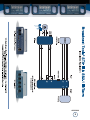
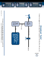
INC
®
Installation and Operation Manual
STA-III
Smart Telephone Autocoupler III
Firmware Version 1.13 or greater / PCB Ver B
Manual Revised 07/12/2011
Due to the dynamic nature of product design, the information contained in this
document is subject to change without notice. Broadcast Tools, Inc., assumes no
responsibility for errors and/or omissions contained in this document. Revisions
of this information or new editions may be issued to incorporate such changes.
Broadcast Tools® is a registered trademark of Broadcast Tools, Inc.
Copyright„ 1989 - 2011 by Broadcast Tools, Inc. All rights reserved.
No part of this document may be reproduced or distributed without permission.
Visit www.broadcasttools.com for important product update information.
STA-III Installation and Operation Manual
INTRODUCTION
Thank you for your purchase of a Broadcast Tools® Smart Telephone
Autocoupler-III (referred to as the STA-III throughout this manual). We’re
confident that this product will give you many years of dependable service.
SAFETY INFORMATION
Only qualified personnel should install Broadcast Tools® products. Incorrect or
inappropriate use and/or installation could result in a hazardous condition.
CAUTION!
Broadcast Tools®
Products, as with any
electronic device, can
fail without warning.
Do not use this product
in applications where a
life threatening condition
could result due to failure.
WHO TO CONTACT FOR HELP
If you have any questions regarding your product or you need assistance, please contact your distributor from whom you purchased this equipment.
If you would like more information about Broadcast Tools® products, you may
reach us at:
NOTE:
This manual should be
read thoroughly before
installation and operation.
Broadcast Tools, Inc.
131 State Street
Sedro-Woolley, WA 98284 USA
Voice: 360 . 854 . 9559
Fax: 866 . 783 . 1742
Internet Home Page: www.broadcasttools.com
E-mail:
[email protected]
THANK YOU FOR CHOOSING
BROADCAST TOOLS® BRAND PRODUCTS!
WEBSITE:
Visit our web site for
product updates and
additional information
INTRODUCTION
e-mail: [email protected] voice: 360.854.9559 fax: 866.783.1742
2
STA-III Installation and Operation Manual
Description
The STA-III provides a convenient interface between a telephone line and the users
equipment. A short list of the features is presented below.
• Auto-answer and auto-disconnect via CPC (calling party control) and/or long
dial tone hang up signals, allowing use behind PBX switches and POTS lines.
• Front panel, plus remote line seize and drop control for manual operation.
• Remote line busy input.
• Electronic telephone hybrid.
• Remote controllable send and receive audio switcher.
• Balanced bridging audio input with automatic signal limiter with front panel
level control.
• Balanced low Z audio output with front panel level control.
• Front panel LED’s display power, ring and valid DTMF tone.
• Two remote controllable SPST relays
• SPST End Of Call relay.
• External hook relay activates when a valid access code is accepted
• User programmable number of rings before auto-answer.
• User programmable up to ten-digit access code, if required.
• User defeatable beep tones on line seize.
• All connections via screw terminals.
• Loop-thru jack. (This is where you would connect your business telephone
system if you were sharing the line.)
• The STA-III’s attractive painted metal chassis may be set on a desktop, mounted on a wall or as part of the new optional RA-1 rack shelf for mounting up
to three units in 1-RU.
Programming
To program, plug a standard touch-tone® telephone into the program jack on the
front panel and press the recessed front panel “PGM” button with a non-metallic
device. The PGM LED will illuminate.
Follow the steps below to set up the STA III.
1 - Enter the number of rings you want the STA-III to answer on. The number
of rings may set from 1 to 10 rings. DTMF “0” equals ten rings.
2 - Enter a “0” if you want to turn OFF the long dial tone hang-up or a 1 if you
want to turn it ON.
3 - Then enter the access code. The access code can be 0 - 12 digits. If no
access code is desired, enter only the number of rings and the long dial tone
code and press the PGM button again to return to normal operation.
Example One: If you want to program the STA-III to answer on the 3rd ring, with
long dial-tone hang up turned OFF and an access code of 567, press the PGM button, enter 30567 and press the PGM button again. You will hear a beep.
DESCRIPTION
e-mail: [email protected] voice: 360.854.9559 fax: 866.783.1742
3
STA-III Installation and Operation Manual
Example Two: If you want to program the STA-III to answer the phone on the first
ring,with long dial-tone hang up turned ON and NO access code, press the PGM
button, enter 11 and press the PGM button again. You will hear a beep.
Factory Defaults:
Number of rings
Access code
CPC
Long dial tone
=1
= NONE
= Always ON
= OFF
Rear panel connector descriptions
Line RJ-11
Loop RJ-11
A-INA / A-INB
A-GND
A-OUT/A-OUT
DROP input
SEIZE input
D-GND
RING
CE-A/CE-B
AUX-A/AUX-B
HK-A/HK-B
PGM-A/PGM-B
BUSY input
PWR /12 VAC
Used to connect to a loop start POTS telephone line.
Used to loop-thru other telephone equipment. This jack is
disconnected from the telephone line when the STA-III is offhook.
Balanced input to the (Send) telephone line.
Analog ground. Tied to PCB circuit ground.
Balanced output (Caller) from the telephone line.
TTL compatible input pulled up to 5vdc. Momentary contact
closure to D-GND will drop an off hook connection.
TTL compatible input pulled up to 5vdc. Momentary contact
closure to D-GND will seize the telephone line.
Digital ground. Tied to PCB circuit ground.
Open Collector output. Must be pulled up in some applications. Goes to ground on each ring occurrence. Limit load to
12 vdc @ 100ma.
Call End relay (K2). Dry normally open relay contacts close
for 1 second at the end of a call.
AUXiliary relay (K3).Dry normally open relay contacts.
HooK Relay (K4). Dry normally open relay contacts close
when a valid access code is accepted or the SEIZE function is
initiated.
PGM Relay (K5). Dry normally open relay contacts
TTL compatible input pulled up to 5vdc. Sustained contact
closure to D-GND will BUSY out the phone line.
2.1mm Coax type power connector. Only use a 12 VAC
power transformer rated at 500 ma to 1 amp.
NOTE:
To verify firmware version numbers enter 98*.
This command may not
work on older versions
of firmware.
WEBSITE:
Visit our web site for
product updates and
additional information
DESCRIPTION
e-mail: [email protected] voice: 360.854.9559 fax: 866.783.1742
4
STA-III Installation and Operation Manual
Front Panel description
DROP Switch
SEIZE Switch
LED Indicators
Pgm Switch
Receive Lvl
Send Lvl
Pgm RJ-11 Jack
Pwr Led
Used to drop an active call/connection
Used to force the STA-III Off-Hook.
Hook, Illuminates when connected to a telephone line (OffHook). Tone, Lights when a valid DTMF is detected.
Ring, Illuminates on each ring occurrence.
Pgm, Lights when in program mode.
Program switch, recessed switch used to put the STA III in
program mode.
Note: Use a non-metallic device to insert into the front panel
switch hole
This control adjusts the audio level from the caller.
This control adjusts the send level to the telephone line.
Attach a touch-tone (DTMF) telephone for programming purposes. Talk-battery is provided.
Illuminates when power is applied.
Installation
Follow the steps below:
Step 1 Connect your air monitor to the balanced (SEND) input labeled “A-INA / AINB”. Adjust the front panel SEND LVL trimmer for a good level and check
for proper DTMF detection operation. Note: If the send level is to high, the
unit may have trouble detecting the DTMF tones. Moving the guard time
jumper JP3 to the “SLOW” position will also enhance tone detection.
Step 2 Connect your input equipment to the balanced (CALLER) output of the
STA-III to your equipment. The output terminals are labeled “A-OUT / AOUT”. The level may be adjusted on the front panel. This control is labeled
RECEIVE LVL.
Step 3 Connect the required relays and/or function inputs to the rear panel screw
terminals.
Step 4 Connect any shared telephone equipment to the rear panel LOOP RJ-11 jack.
Step 5 Connect the supplied 12 vac wall transformer to power jack on the rear panel
of the STA III.
INSTALLATION
e-mail: [email protected] voice: 360.854.9559 fax: 866.783.1742
5
STA-III Installation and Operation Manual
Operation
Auto-Answering a call:
Step 1 Answers after ring count set by user
Step 2 Goes off hook and beeps
Step 3 The users enters a valid access code, (if applicable) and relay K4
(external hook) closes.
Step 4 The send and receive audio is enabled. NOTE: Be sure you have
enabled the send/caller audio with the commands below.
Dropping a call:
Hang up occurs with a 12 second dial tone (if enabled), CPC, *99, front or rear panel
drop function.
NOTE: CPC and loss of loop current ignored if, an off-hook condition is initiated by a remote or front panel SIEZE function.
Controlling the send and caller audio:
* 9 # turns OFF send (to phone line) audio
* 9 * turns ON send audio
* 8 # turns OFF caller (from telephone line) audio
* 8 * turns ON caller audio
Relay Operation:
The CE Relay (CE-A/CE-B) K2 closes for 1 second when hang up occurs.
WEBSITE:
External Hook (HK-A/HK-B) Relay K4 turns ON when a valid access code is
accepted or the SEIZE function is initiated.
Visit our web site for
product updates and
additional information
3 * turns ON “AUX” Relay K3
3 # turns OFF “AUX” Relay K3
3 0 turns ON “AUX” Relay K3 for one second
5 * turns ON “PGM” Relay K5
5 # turns OFF “PGM” Relay K5
5 0 turns ON “PGM” Relay K5 for one second
OPERATION
e-mail: [email protected] voice: 360.854.9559 fax: 866.783.1742
6
STA-III Installation and Operation Manual
SPECIFICATIONS
CAUTION!
Send input level:
Adjustable, MIL +24dbu, balanced 20 K Ω
bridging (Input to Phone line).
Caller output level:
Adjustable, Off to +4 dbu, @ 100 Ω, balanced
output (Receive from phone line).
Logic:
Flash microprocessor, non-volatile memory,
DTMF transceiver.
Relays/OC:
Relays, four SPST. 30 vdc @ 1 amp. Open
collector (Ground Sink), 12 vdc @ 100 ma.
For safety, do NOT
connect 120 Volt circuits to the relays.
Drop, Seize and Busy inputs: Compatible with CMOS/TTL, open collector
or contact closures. Active low. Max logic
voltage 5 vdc.
Connectors:
Screw style wire captive terminals. 3 Modular, RJ-11C/W programming telephone,
phone line and loop-thru. 1- Modular cable
supplied.
FCC registration:
Complies with FCC parts 15 & 68. Reg
BRDUSA-36042-OT-T
Ringer equivalence:
0.4B
Power Requirements:
12 Vac, @ 500 ma or 1 amp. 120 Vac wall
transformer. Supplied.
Size:
5.65” x 6.50” x 1.55” (WDH)
Weight:
2.0 lbs.
Options:
RA-1 rack shelf for mounting up to three units
in 1-RU, CE 240 Vac 50-60 hz wall transformer.
WEBSITE:
Visit our web site for
product updates and
additional information
SPECIFICATIONS
e-mail: [email protected] voice: 360.854.9559 fax: 866.783.1742
7
STA-III Installation and Operation Manual
LIMITED WARRANTY
The term “Buyer” as used in this document refers to and includes both (but only) (a) any person or entity who acquires such an item for
the purpose of resale to others (i.e., a dealer or distributor of an item), and (b) the first person or entity who acquires such an item for
such person’s or entity’s own use.
Broadcast Tools warrants to each Buyer of any item manufactured by Broadcast Tools that the item will be free from defects in materials and workmanship at the time it is shipped by Broadcast Tools if the item is properly installed, used and maintained.
EXCLUSIVE REMEDIES
If Broadcast Tools is notified, in writing, of a failure of any item manufactured by Broadcast Tools to conform to the foregoing Limited
Warranty within one (1) year following the date of the Buyer’s acquisition of the item, and if the item is returned to Broadcast Tools in
accordance with Broadcast Tools’ instructions for confirmation by inspection of the defect (which at Broadcast Tools’ election may
include, without limitation, a requirement that the Buyer first obtain a Return Authorization number from Broadcast Tools, that the Buyer
furnish proof of purchase in the form of an invoice and/or receipt, and that the Buyer prepay all freight charges associated with any return
of the item to Broadcast Tools using such freight service as Broadcast Tools reasonably may specify), Broadcast Tools will repair or
replace the defective item, or will refund the purchase price paid by the Buyer for the item. Broadcast Tools shall have the exclusive
right to choose between these alternative remedies.
NO OTHER WARRANTIES OR REMEDIES
TO THE MAXIMUM EXTENT PERMITTED BY APPLICABLE LAW, BROADCAST TOOLS AND ITS SUPPLIERS DISCLAIM ALL OTHER
WARRANTIES, EITHER EXPRESS OR IMPLIED, INCLUDING BUT NOT LIMITED TO IMPLIED WARRANTIES OF MERCHANTABILITY OR FITNESS FOR A PARTICULAR PURPOSE; AND THE FOREGOING ALTERNATIVE REMEDIES SHALL BE EXCLUSIVE OF
ALL OTHER REMEDIES. THIS LIMITED WARRANTY GIVES YOU SPECIFIC LEGAL RIGHTS. YOU MAY HAVE OTHER RIGHTS,
WHICH VARY FROM STATE/JURISDICTION TO STATE/JURISDICTION.
NO LIABILITY FOR CONSEQUENTIAL DAMAGES
TO THE MAXIMUM EXTENT PERMITTED BY APPLICABLE LAW, NEITHER BROADCAST TOOLS NOR ANY OF ITS SUPPLIERS
SHALL HAVE ANY LIABILITY FOR ANY SPECIAL, INCIDENTAL, INDIRECT, CONSEQUENTIAL OR PUNITIVE DAMAGES WHATSOEVER (INCLUDING, WITHOUT LIMITATION, ANY DAMAGES FOR LOST PROFITS, BUSINESS INTERRUPTION, LOSS OF DATA OR
INFORMATION, COST OF CAPITAL, CLAIMS OF CUSTOMERS, OR ANY OTHER PECUNIARY LOSS) ARISING OUT OF THE USE
OF OR THE INABILITY TO USE ANY ITEM SUPPLIED BY BROADCAST TOOLS, EVEN IF BROADCAST TOOLS HAS BEEN
ADVISED OF THE POSSIBILITY OF SUCH DAMAGES HAVE ANY LIABILITY FOR ANY SPECIAL, INCIDENTAL, CONSEQUENTIAL,
EXEMPLARY OR PUNITIVE DAMAGES. THIS LIMITATION OF LIABILITY APPLIES WHETHER A CLAIM IS ONE ALLEGING
BREACH OF A CONTRACT OR WARRANTY, NEGLIGENCE OR OTHER TORT, FOR THE VIOLATION OF ANY STATUTORY DUTY,
THE FAILURE OF ANY LIMITED OR EXCLUSIVE REMEDY TO ACHIEVE ITS ESSENTIAL PURPOSE, OR ANY OTHER CLAIM OF
ANY NATURE. BECAUSE SOME STATES AND JURISDICTIONS DO NOT ALLOW THE EXCLUSION OR LIMITATION OF LIABILITY
FOR INCIDENTAL OR CONSEQUENTIAL DAMAGES, THIS LIMITATION MAY NOT APPLY TO YOU.
Broadcast Tools, Inc.
131 State Street
Sedro-Woolley, WA 98284 • USA
360.854.9559 voice • 866.783.1742 fax
[email protected] e-mail
www.broadcasttools.com website
LIMITED WARRANTY
e-mail: [email protected] voice: 360.854.9559 fax: 866.783.1742
8
STA-III Installation and Operation Manual
APPENDIX – APPLICATION
APPENDIX
9
STA-III Installation and Operation Manual
RJ11
Duplex
Adapter
Broadcast Tools®
DSL MODEM
* DC-8A, DC-8 Plus,
Site Sentinel 8 w/ Voice,
STA-III, STI-II, VAD-2,
VAD-2 Plus, WVRC-4,
WVRC-8
RJ11 Modular Cable
Telco
RJ11
Modular Cable
DSL
Filter
(Required
for proper
operation)
131 State Street, Sedro-Woolley, WA 98284-1503 • 360.854.9559 • Fax 866.783.1742
Visit us online at www.broadcasttools.com
Copyright © 1989-2011 by Broadcast Tools, Inc. All Rights Reserved.
Ethernet
10
e-mail: [email protected] voice: 360.854.9559 fax: 866.783.1742
Connection suggestion when using listed* equipment with DSL/Telco Phone Lines.
Modification Date: 07/12/11
APPENDIX