1
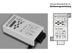
Universal Control Unit UC-1-E
User Manual
General Information
Universal Control Unit
UC-1 Of Central Lubrication
PAUSE
CONTACT
SET
CS
PS
DK
FAULT
CC DC 24 V
5A
PS/CS
15
DK/MK
M
SL
31
M
Z
30
General Information
Contents
Universal Control Unit UC-1-E
External Universal Control Unit UC-1-E is designed for controlling and monitoring of centralized
lubrication systems of construction machinery,
vehicles and machine lubrication. Universal Control Unit UC-1-E is compatible with Vogel
IG502-E control unit.
UC-1-E stores configuration data and parameters
in EEPROM, which makes UC-1-E store data
safely for long period without backup power
supply.
The control unit uses LCD display to show information.
Factory Setting UC-1-E
Pause mode:
Pause time:
Contact mode:
Contact time:
Initial password:
System monitoring:
time
1h
time
4 min (240 sec)
0000
Pressure Switch OFF
Cycle Switch
OFF
Page
1.
Safety Warning Instructions!
2
2.
2.1
2.2
2.3
Installation
Installation dimensions
Electrical connection
Cable harness, connector
2
3
4
4
3.
3.1
3.2
3.3
3.4
Display and control panel
LCD display
LED signal lights
Keys
SL signal lights
5
5
5
6
6
4. Display mode
4.1 Display operation
7
7/8
Page
7.
7.1
7.2
7.3
7.4
7.5
7.6
7.7
Faults
Fault display
Fault message clearance
Block operation
Block operation diagram
No Signal from cycle switch
Block operation at display
Fault indication cycle switch at display
No signal from pressure switch
Fault message storage
13
13
13
14
14
15
15
15
16
16
8.
Technical data
16
9.
Service address
5. Programming
8
5.1 Start pogramming mode
8
5.2 Modify pause and/or contact
parameters
9
5.3 Change system monitoring settings 9/10
5.4 Change pause and/or contact
control modes
10
5.5 Change password
11
6.
6.1
6.2
6.3
6.4
6.5
6.6
Operating modes
Timer operation
Counter operation
Combination operation
Operation without system monitoring
Operation with system monitoring
Power-off protection function
12
12
12
12
12
12
12
1
1. Safety instructions
General information
Qualified personnel
2. Installation
Universal Control Unit UC-1-E is designed and
manufactured not only in conformity with the
general engineering standards, industrial safety
and accident prevention regulations, but also in
accordance with some relevant general industrial
technical acceptance standards.
Although this unit complies with relevant safety
technical requirements, the use of the unit may
still entail dangers leading to personal injury of
the user or third parties or damage to property.
Therefore, the unit must be used when it is in
correct technical condition. And the operation
must strictly comply with operation manual. Errors
that may affect safety must be rectified immediately.
Universal control unit UC-1-E may be used exlusively controlling and monitoring centralized
lubrication systems. The user himself shall be
liable for any damage caused by improper use.
Universal control unit UC-1-E may be installed,
operated, maintained and repaired only by qualified personnel.
Qualified personnel means persons trained,
assigned and instructed by the operator of the
equipment concerned. These persons are familiar
with the applicable norms, rules, accident prevention regulations and operating conditions on
account of their training, experience and the
instructions received. They are entitled to carry
out the activities required in a given case and
will be able to recognize and avoid possibly
existing dangers. DIN VDE 0105 or IEC 364
contains the definitions for specialists and the
prohibition to use unqalified personnel.
Universal Control Unit UC-1-E is designed to
work in a closed compartment or machine cabin
of vehicle to protect it from environmental
influences.
If the control unit is installed at an inaccessible
position, it is advisable to install additional signal
lights and illuminated pushbutton on the
dashboard. In that case the operating situation
of the control unit can be monitored.
Potential electrical dangers
This unit must be connected to the power supply
only by trained qualified personnel in accordance
with the local electrical and technical regulations.
Improper connection may lead to serious personal
injury.
This unit is designed to use in battery-powered
on-board electric systems of vehicles and engineering equipment. When it is used for any other
purposes, all safety regulations should be complied with.
2
Exclusion of liability
• Occurred due to lack of lubricant
• Caused by soiled or improper lubricant
• Caused due to the installation of wrong
components or spare parts
• Caused due to any use non-compliant
with the intended purpose
• Due to faulty installation and filling
• Due to wrong electrical connection
• Due to wrong programming
• Due to improper reaction to failures
2.1 Installation dimensions
65
80
65
5.2
STATUS: PAUSE
TIMER MODE
8.2
Universal Control Unit
UC-1 Of Central Lubrication
40
PAUSE
CONTACT
SET
CS
DK
PS
137
120
103
FAULT
CC DC 24 V
5A
PS/CS
15
DK/MK
M
SL
31
M
Z
30
80
3
2.2 Electrical connection
PS/CS
External Pressure Switch (PS)
or Cycle Switch (CS)
15
Positive pole of power supply
of UC-1-E
+M
Pump motor (positive)
+SL
External Signal Light (positive)
DK/MK External pushbutton
(timer operation) DK
Counter signal input
(counter operation) MK
31
Ground (minus)
Z
Ignition lock
30
Positive pole of power supply
to ignition lock
F
5A fuse (control unit protection)
5A
Note: Universal Control Unit UC-1-E has two
models of 12V and 24V available. Please make
sure that the system voltage of vehicle or machine
matches the voltage claimed on the control unit.
15
DK/MK
M
SL
31
M
UC-1-E 24, voltage limit range
min 18VDC – max 36VDC
UC-1-E 12, voltage limit range
min 9VDC – max 18VDC
If the lowest required voltage is not guaranteed,
please use a Low Voltage Protector to insure
control unit function.
30
SL
31
15
DK/MK
Electrical connection of external
illuminated pushbutton diagram
4
Cable harness for external
Control Unit order no. GF200-005
Z
Terminal connection diagram
16
When UC-1-E is operating, be sure the vehicle
or machine system voltage is within power voltage
limit range. Voltage that is lower or higher than
the limit range will damage the control unit or
causes functional problems.
2.3 Cable Harness, Connector
PS/CS
Ø 1,5-2,5
Female Connector for six-blade terminals
order no. GF 200-015.K
28
0,8
Blade Terminal 6,3-0,8/25
order no. GF 200-016.K
Material: Brass
3. Display and control panel
3.2 LED signal light
Film panel protects UC-1-E from humidity and
dust. Please use soft cloth with warm water or
neutral detergent to clean the film panel.
Organic solvent is prohibited because the film
is made of organic material. Do not use sharp
tools/ objects to touch the panel.
PAUSE
Universal Control Unit
UC-1 Of Central Lubrication
PAUSE
LED “PAUSE” is on: Power is supplied to pump
and control unit. System is in PAUSE time
function.
LED “PAUSE” flashes:
1. Control unit is in PAUSE programming mode.
The value and control mode of PAUSE can be
changed.
2. When Cycle Switch monitoring is activated,
LED “PAUSE” and “CS” will change to flash and
indicates control unit is in PAUSE phase of a
block operation.
CONTACT
SET
CS
PS
DK
FAULT
3.1 LCD display
STATUS: PAUSE
TIMER MODE
LCD display shows operating status and
parameters. It is deactivated normally.
To activate it, press key
or
PAUSE:
Pause signal light.
CONTACT:
CONTACT Lubrication signal light
LED “CONTACT” is on: Power is supplied to
pump and control unit. System is in CONTACT
time function. (Pump motor gets power supply
from UC-1-E)
LED “CONTACT” flashes:
1. Control unit is in CONTACT programming
mode. The value and control mode of CONTACT
can be changed.
2. When CS (Cycle Switch) monitoring is
activated, LED “CONTACT” and “CS” will be
change to flash and indicates control unit is in
drive phase of a block operation.
CS
Cycle switch will monitor the progressive
distributor during pump running time.
LED “CS” flashes:
1. Control unit is in programming status for
monitoring setting. At this status, the mode “Off
Monitoring” can be altered; Cycle Switch
monitoring can be activated or deactivated.
2. When CS (Cycle Switch) monitoring is
activated, LED “CONTACT” (or “PAUSE”) and
LED “CS” will change to flash and indicates
control unit is in block operation.
PS
PS: External pressure switch
signal light
LED “PS” is on: A pressure switch is used for
monitoring the system. Monitoring of pressure
during pump running time.
LED “PS” flashes:
Control unit is in programming status for
monitoring setting. At this status, the mode “Off
Monitoring” can be altered; the Pressure Switch
monitoring can be activated (on) or deactivated
(off).
FAULT
FAULT:
Fault signal light
LED “FAULT” flashes quickly: Control unit
indicates a system fault.
Press key
or
, the fault message will be
shown on LCD display.
CS. External cycle switch
signal light
LED “CS” is on: A Cycle Switch is used for
monitoring the lubrication system.
5
3.3 Keys
3.4 External Signal Light SL
Activate display in “Show” mode. Increase
or decrease
the displayed value at cursor
position by “1” in programming mode.
Press key
scroll left or right key to roll up
the menu in menu operation.
To move the cursor position when input
parameters in programming mode
Press key
SET
for next menu step
SET
Activate programming mode. Confirm entered
values or option.
DK
DK
To initiate an intermediate lubrication cycle press
“DK” once during PAUSE time operation.
In FAULT status, operate this key to clear fault
message and get system back to normal
lubrication cycle.
6
If an external signal light SL has been installed,
SL will flash for 3 sec after the ignition lock is
started. This is for UC-1-E function control.
Note: Control unit needs a certain time to save
the operating parameters after switching off supply
(so that the lubrication tasks of the control unit
could be continued after the break).
The interval of the power-off and next power-on
should not be shorter than 3 sec. Otherwise,
control unit may not start properly, and SL will
not flash. (When the control unit is performing
the lubrication tasks, Light “SL” will be on, denoting
the state of lubrication; If the monitoring system
finds a fault, light “SL” will be flashing, remind
the user that there is a lubrication system function
problem.
If control unit is in FAULT status you can activate
system with DK to get it back to normal function
within an intermediate lubrication cycle.
Requirement is repair of malfunction. This is
necessary to continue lubrication task after the
break with current stored data. Denoting that
lubrication system, pump is just working
4. Display mode
Briefly press key
or
to activate display.
The current values and the preset parameters
are shown. During normal operation, LED signal
lights are used to show current status of the
control unit.
4.1. Display operation
3. Press
, displays the remaining pause time.
Example: 006 h 48 min
(The remaining PAUSE time of the
current lubrication cycle is 6 h and 48 min)
CONTACT REMAIN
PAUSE REMAIN
006 h 48 min
PAUSE
CONTACT
SET
CS
PS
SET
CS
DK
CS
PS
DK
FAULT
4. Press
, displays preset parameter of pause
time.
Example: 009 h 00 min
(Preset total pause time is 9 h)
PAUSE VALUE
009 h 00 min
PAUSE
PAUSE
CS
PS
7. Press
, displays preset parameter of
CONTACT.
Example: 00 h 06 min 30 sec
(Preset total lubrication time is 6 min and 30 sec)
CONTACT VALUE
00 h 06 min 30 sec
PAUSE
CONTACT
CONTACT
SET
CS
DK
SET
CS
PS
DK
FAULT
5. Press
, displays the control mode of
CONTACT.
Example: TIMER (The control mode of pump
is time operated)
CONTACT REMAIN
PAUSE
DK
8. Press
, to display system monitoring.
Displayed content may be: PRESSURE SWITCH
(Monitoring with pressure switch)
MONITORING
PRESSURE SWITCH
SET
CS
PS
PAUSE
CONTACT
SET
CS
CONTACT
FAULT
PS
FAULT
CONTACT
SET
PS
FAULT
FAULT
STATUS: PAUSE
TIMER MODE
CONTACT
CONTACT
DK
2. Briefly press key
or
to activate display
mode and to show the current operating status
of the control unit.
Example: PAUSE & TIMER MODE (Pause time
in timer mode)
PAUSE
PAUSE
SET
1. Press key
, display control unit´s Serial
Number.
Example:: 07010001
CONTROL UNIT
SN: 07010001
6. Press
, ”- - -” is shown.
Because system is now in PAUSE time function.
There is no remaining value of CONTACT time.
PS
DK
FAULT
DK
FAULT
7
5. Programming
or CYCLE SWITCH
(Monitoring with cycle switch)
MONITORING
CYCLE SWITCH
PAUSE
10. Press
Shows total fault hours.
Since installing control unit
Example: 000017 h 25 min
Maximum value: 9 9999 h 59 min
CONTACT
SET
CS
PS
FAULT TIME
000017 h 25 min
PAUSE
CONTACT
DK
FAULT
SET
CS
or OFF
(Monitoring disabled, no monitoring function)
MONITORING
OFF
PAUSE
CONTACT
SET
CS
PS
DK
FAULT
PS
DK
FAULT
11. Press
display will be switched off.
Total operation hours and total fault hours will
not be erased.
They are permanently stored in EEPROM and
can be indicated
Press SET longer than 2 sec to activate
programming mode. All preset parameters and
control mode can be changed now.
Please note: Programming always starts with
two steps.
5.1 Start programming
First step
1. Press SET longer than 2 sec, the control
unit will then ask for password.
Please enter the preset password.
PASSWORD
0000
PAUSE
CONTACT
SET
CS
PS
DK
FAULT
9. Press
Shows total UC-1-E hours.
Since installing control unit
Example: 000003 h 48 min
Maximum value: 9 9999 h 59 min
OPERATION TIME
000003 h 48 min
Second step
2. Press SET again to confirm password.
LCD now shows PROGRAMMING. And the
default operation is “SET PARAMETERS”.
PAUSE
CONTACT
SET
CS
PS
DK
PROGRAMMING
SET PARAMETERS
PAUSE
CONTACT
SET
CS
FAULT
PS
DK
FAULT
8
5.2 Change of pause and contact values
(Carry out steps 1-2)
3. Briefly press SET to display the preset PAUSE
value. LED “PAUSE” flashes.
Example: 1 h
6. Use keys
,
,
,
to
set new contact value.
Example: new value is 3 min
CONTACT VALUE
00 h 03 min 00 sec
PAUSE
CONTACT
5.3 Change system monitoring settings
Carry out steps 1-2)
3. Press key
till SET
”MONITORING” is shown on the second line of
the LCD and LED “CS” or “PS” are flashing
SET
CS
PAUSE VALUE
009 h 00 min
PAUSE
PS
DK
FAULT
CONTACT
PROGRAMMING
SET MONITORING
CONTACT
SET
CS
FAULT
4. Use keys
,
,
,
to
change pause values.
Example: new value is 2 h 30 min
PAUSE VALUE
002 h 30 min
SET
PS
DK
PAUSE
CONTACT
SET
CS
7. Press
SET
to confirm the new contact value.
8. LCD flashes to remind user all new values
are confirmed. Then press SET a second time for
more than 2 sec without releasing, LCD stops
flashing; New values are saved permanently and
display switches off.
Note: If pressingSET shorter than 2 sec, the
control unit will give up new values and go back
to the initial state of PROGRAMMING.
CS PS
DK
FAULT
5. Press SET to confirm the new PAUSE value.
LED “PAUSE” switches off and LED “CONTACT”
Flashes. The preset contact value will be shown
Example: 4 min 15 sec
CONTACT VALUE
00 h 04 min 15 sec
PAUSE
PS
DK
FAULT
4. Briefly press SET to get into system monitoring
setting status. The current monitoring mode is
shown.
Example: ”PRESSURE SWITCH”
Monitoring via pressure switch.
SET MONITORING
PRESSURE SWITCH
PAUSE
CONTACT
! To program new settings it is always necessary
to press SET two times.
1. for confirming the new value
2. for storing the new value
SET
CS
PS
DK
FAULT
5. Press
, or
, to select monitoring mode.
Example: LED “CS” flashes, “CYCLE SWITCH”
is selected. (Monitoring via cycle switch)
PAUSE
CONTACT
SET MONITORING
CYCLE SWITCH
PAUSE
CONTACT
SET
CS
PS
DK
FAULT
SET
CS
PS
DK
FAULT
9
or select “OFF to deactivate system monitoring.
(LED “CS” and “PS” switches off)
SET MONITORING
OFF
PAUSE
CONTACT
SET
CS
PS
5.4 Change pause and contact control
mode (Carry out steps 1-2)
3. Press
till “SET CONTROL MODE” is
displayed on the second line of the LCD, and
LED “PAUSE” and “CONTACT” flashing are
together.
6. Press SET to confirm the new “PAUSE“ mode.
LED “PAUSE” will switch off. “CONTACT” flashes.
The preset “CONTACT MODE“ will be shown
Example: “TIMER“
CONTACT MODE
TIMER
CONTACT
DK
FAULT
PROGRAMMING
SET CONTROL MODE
SET
CS
PAUSE
to confirm the new settings
7. LCD starts flashing to remind user that all new
settings are confirmed.
Then press SET a second time for more than
2 second without releasing, LCD stops flashing;
2 second later, the new values are saved
permanently and display switches off.
Note: If pressing SET shorter than 2 second, the
control unit will give up new settings and go back
to the initial state of “PROGRAMMING“.
CS
PS
DK
FAULT
4. Briefly press SET to get into “PAUSE MODE“
setting.
LED “PAUSE” flashes.
The current pause mode will be shown
Example: “TIMER“ (factory setting)
PAUSE MODE
TIMER
PAUSE
CONTACT
! To program new settings it is always necessary
to press SET two times.
1. for confirming the new value
2. for storing the new value
SET
CS
FAULT
PAUSE MODE
COUNTER
PAUSE
CONTACT
SET
CS
7. Press
or
to change “CONTACT MODE“.
Example: “COUNTER“
CONTACT MODE
COUNTER
PAUSE
CONTACT
SET
CS
PS
DK
FAULT
8. Press
MODE“.
SET
to confirm the new “CONTACT
PS
DK
5. Press
or
to change “PAUSE MODE“.
Example: “COUNTER“
PS
DK
FAULT
10
FAULT
SET
SET
PS
DK
CONTACT
6. Press
PAUSE
9. LCD starts flashing to remind user that all new
settings are confirmed. Then press SET a second
time for more than 2 second without releasing,
LCD stops flashing; 2 second later, the new
values are saved permanently and display
switches off.
Note: If press SET shorter than 2 second, the
control unit will give up new settings and go back
to the initial state of “PROGRAMMING“.
! To program new settings it is always necessary
to press SET two times.
1. for confirming the new value
2. for storing the new value
5.5 Change password
(Carry out steps 1-2)
5. Edit 4 digits new password.
Example: 6666
The password area of UC-1-E is 0000 To 9999.
Control unit has no limitation within this area.
CHANGE PASSWORT
6666
CONTACT
Once the password is changed, the password
set by factory will be erased. The new password
is saved till next change.
3. Press
till “CHANGE PASSWORD” is
shown on the second line of the LCD.
PROGRAMMING
CHANGE PASSWORD
PAUSE
CONTACT
SET
CS
PS
DK
FAULT
4. Briefly press SET to get into “CHANGE
PASSWORD“ status.
PROGRAMMING
0000
PAUSE
CONTACT
SET
CS
PS
DK
FAULT
PAUSE
SET
CS
PS
DK
FAULT
6. Press
SET
to confirm the new password.
7. LCD starts flashing to show user that new
password is confirmed. Then press SET a second
time, without releasing, LCD stops flashing.
2 second later, the new values are saved
permanently and display switches off.
Note: If press SET less than 2 second, the
control unit will give up new password and go
back to the initial state of “PROGRAMMING“.
Please note:
The password should be kept in safe place.
If the password gets lost, the programming of
parameters for the control unit is impossible. In
case of that, the control unit has to be sent back
to the factory.
! To program new settings it is always necessary
to press SET two times.
1. for confirming the new value
2. for storing the new value
11
6. Operating modes
6.1 Timer operation
Set “TIMER” for PAUSE and CONTACT.
The control of the lubrication cycle takes place
based on the values preset for PAUSE and
CONTACT times. It carries out the operation
cycle of “PAUSE – CONTACT”: Within pressing
DK , an intermediate lubrication cycle is activated
or the displayed fault message is cleared. External
DK button can be connected to the terminal
DK/MK.
6.2 Counter operation
(Pause depends on impulses)
Set “COUNTER” for PAUSE and “TIMER” for
CONTACT.
Connect an external impulse transmitter to the
terminal DK/MK.
PAUSE: Display and program values in impulses.
CONTACT: Display and program values in
minutes.
6.3 Combined operation
(Pump running is controlled by impulse)
PAUSE: Display and program values in impulse
or time.
CONTACT: Display and program values in
impulses.
Users may combine: “COUNTER MODE” of
pause with “COUNTER MODE” of contact, or
“TIMER MODE” of pause with “COUNTER
MODE” of contact.
12
6.4 Operation without system
monitoring
Lubrication cycle performs only according to the
preset values of PAUSE and CONTACT time.
Fault monitoring is disabled in this setting.
Monitoring function must be disabled. Monitoring
mode has to be “OFF”. Fault signal will not be
detected and shown.
6.5 Operation with system monitoring
In this mode, system can be monitored by an
external sensor.
The following functions can be monitored:
• Filling level in the lubricant tank (only for
pumps filling level monitoring W1 or identical
level monitoring function)
• Pressure build-up in the main line can be
monitored via a pressure switch.
• Function of the progressive feeder can be
monitored via a cycle switch (Blockade
indication) Faults will be detected
automatically and shown at LCD when
system monitoring is activated.
6.6 Power-off protection function
The control UC-1-E has power-off protection
function. When power is cut off, the control unit
automatically remains operating status values,
total operation hours and total fault hours at the
point of power-off. When next ignition starts, the
control unit will continue carrying out operation
from last point of power-off. Control UC-1-E unit
stores operating status and values in EEPROM.
The data can reliable be stored for at least
10 years.
7. Faults
When the control unit detects system faults, LED
“FAULT” on the panel will be flashing. If an
external Signal Light is installed, light “SL” will
also be flashing and reminding user that
lubrication system is in fault function. Meanwhile,
the control unit stops normal operation. The cause
of the fault can be seen from the LCD.
7.1 Display faults
Briefly press
or
to start the display of
fault messages. The meanings of the display are
as followings.
PRESSURE SWITCH: No signal is received
from pressure switch during pump running time.
CYCLE SWITCH: No signal is received from
cycle switch during pump running time.
LOW LEVEL ERROR: The filling level in
lubricant tank has dropped below the minimum
level.
SYSTEM ERROR: Control unit itself has error
inside. If such situation occurs, get the control
unit power off. After 3 seconds switch power on.
If error still exists, please contact the manufacturer.
7.2 Clear fault messages
Press DK to acknowledge and clear fault
messages, and to start a normal lubrication cycle.
Please note: DK has to be pressed after
determining and correcting the fault. The user
himself is responsible for any damages caused
by operating the machine/vehicle/equipment
without correct lubrication.
7.3. Block operation
If CS (Cycle Switch) is programmed, a block
operation will be activated automatically when
no signal from the cycle switch is received during
the pump running time. Follasing function will
take place during block operation
(1). When no signal from CS is received during
the programmed pump running period, the
normal lubrication operation will be aborted.
Then a 15 min interval block operation starts.
During block operation, relevant LED on the
control panel will be flashing to indicate that the
control unit is now performing block operation.
LED “CS” flashes alternative with LED “PAUSE”
means the control unit is now in the Pause phase
of the block operation. LED “CS” flashes
alternative with LED “CONTACT” indicates the
control unit is now in Drive phase of the block
operation.
(2). When the first (15 min pause) block interval
ends, UC-1-E starts driving the pump. If Signal
from CS is received during that pump
operation the block operation will be aborted.
System goes back to normal lubrication cycle.
If there is still no signal from CS, another
second block operation starts.
(3). If signal from CS is received during
second (15 min pause) interval, the block
operation is aborted and the system will go
back to normal operation. If there is no signal
from CS, then the third block operation starts
(4). If the system receives signals from CS
during the third (15 min pause) interval, then
it will switch back to normal lubrication cycle.
If there is still no signal received, then the
block operation is aborted and a fault message
will be shown a LCD Display.
If the preset PAUSE time is shorter than 15 min,
the block pause will correspond to the preset
value.
13
Block operation diagram
! When no signal from the cycle switch is
received,the control unit responds by activating
the block mode of operation.
! If the preset PAUSE time is shorter than 15 min, the
block pause Block Test corresponds to this value.
Delayed signal from cycle switch
No signal from cycle switch during
pump running time
normal
operation is aborted 15 min
block interval begins
with inquiry of cycle switch
Signal from cycle switch during 1st
block interval
block
operation is aborted
Pause interval is continued up to end
of the regular preset pause time
Signal from cycle switch during 2nd
pump running time
block
operation is aborted
Regular preset pause time begins
Signal from cycle switch during 2nd
block interval
block
operation is aborted
Pause interval is continued up to end
of regular preset pause time
If a signal isreceived from the cycle
switch during the 3nd pump running
time
block operation is
aborted
Regular preset pause time begins
14
Contact Block
Time
Test
Contact Block
Time
Test
Pause or Pause
Time
Counter
Contact Block Con.
Time
Test Time
Pause
Pause
Time or Counter
Contact Block Contact Block
Time
Test
Test
Time
Pause
Pause
Time or Counter
Contact Block Contact Block Con. Pause or Pause
Counter
Time
Test
Time
Test Time Time
Display on control panel
No Signal from cycle switch
Three pump running times and two block intervals
without signal from cycle switch
Block
operation is abortted, a fault message
is displayed!
CONTACT MODE
TIMER
Contact Block Contact Block Contact
Time
Test
Time
Test
Time
7.5 Fault indication CYCLE SWITCH at
display
If a ”CS” fault massage is display ed LED FAULT
flashes and will hear alternately a ”klick” noise
PAUSE
CONTACT
PAUSE
CONTACT
SET
CS
SET
! Determine and rectify cause of fault
CS
PS
FAULT
DK
Press key
to activate display and show
system status
FAULT
7.4 Block operation at display
Block operation with CS mode and PAUSE
function
Block operation with CS mode and CONTACT
function
FAULT
CYCLE SWITCH
PAUSE
CONTACT
SET
CS
PAUSE
PAUSE
CONTACT
CONTACT
SET
SET
CS
PS
CS
DK
PS
PS
DK
FAULT
Display shows: FAULT CYCLE SWITCH
DK
FAULT
If system is in block operation pause time function
with CS mode you will see alternately flasching
of PAUSE LED and CS LED
PAUSE time function block test
Press key
to activate display and show
system status
STATUS:
BLOCK TEST
PS
DK
PAUSE
FAULT
If system is in block operation contact time function
with CS mode you will see alternately flasching
of CONTACT LED and CS LED
CONTACT time function block test
Press key
to activate display and show
system status
STATUS:
BLOCK TEST
PAUSE
CONTACT
SET
CONTACT
SET
CS
PS
DK
CS
PS
DK
FAULT
Display shows: BLOCK TEST
FAULT
Display shows: BLOCK TEST
15
7.6 No signal from pressure switch
If PS (Pressure Switch) monitoring is programmed, normal operation will automatically stop
when no signal from the pressure switch is
received during the pump running. Fault message
is displayed after block operation.
7.7 Storage of fault messages
The time that has elapsed since the occurrence
of the fault message up to its acknowledgement
will be added up and saved automatically. And
the saved fault time is non erasable.
The maximum saveable fault time is
999999 hours and 59 min. And the minimum
saveable fault interval is 1 min.
16
8. Technical Data
Voltage of power supply
12VDC
24VDC
min 9V to max18V
min 18V to max36V
Type of protection
IP20
Max. Load output M
5A
SL output (Signal Light)
5W
Data storage
No limitation
Operating temperature
-25°C up to + 75 °C
Storage temperature
-40°C up to + 80°C
Fuse max:
5A
Installation dimensions L x W x H
137mm x 92mm x 42mm
Programmable contact time:
1 s to 17h 59min 59s
Programmable pause time
1 min to 999h 59min
Programmable impulses
1 to 59999
Operation hour Memory
0 to 999999 h 59 min
Fault our Memory
0 to 999999 h 59 min
Operating temperature without display function
-40°C up to +80°C
9. Service Address
TD001-GB-24-07