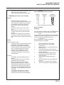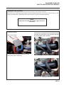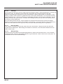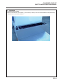
1
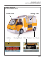
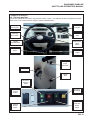
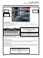
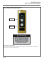
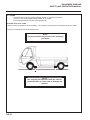
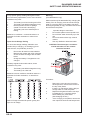
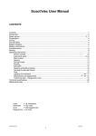
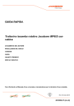
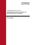
24882G-GB (rev.0)
Safety, Operation & Service Manual
DIABLINE
WARNING: If incorrectly used this machine can
cause severe injury. Those who use and maintain
this machine should be trained in its proper use,
warned of its dangers and should read the entire
manual before attempting to set up, operate, adjust
or service the machine.
RJL 100 June 2009
WARNING
DO NOT USE THIS VEHICLE
UNLESS YOU HAVE BEEN
TRAINED IN ITS USE AND SAFETY.
TRAINING CONSISTS OF
KNOWLEDGE OF THE WORK
REGULATIONS OF YOUR
EMPLOYER, INSTRUCTIONS IN
THIS MANUAL AND THE CURRENT
REGULATIONS FOR THIS TYPE
OF MACHINE.
A NON-QUALIFIED OPERATOR
IS EXPOSED TO AND EXPOSES
OTHERS TO THE RISK OF
SERIOUS INJURY.
© 2009, Ransomes Jacobsen Limited. All Rights Reserved
RANSOMES DIABLINE
SAFETY AND OPERATORS MANUAL
TABLE OF CONTENTS
A.1
INTRODUCTION .............................................................................. 9
A.2
A.2.1
A.2.2
GENERAL DESCRIPTION
DESCRIPTION OF THE VEHICLE ................................................. 11
DIMENSIONS AND TECHNICAL CHARACTERISTICS ................. 12
A.3
A.3.1
A.3.1.1
A.3.1.2
A.3.2
A.3.3
A.3.3.1
A.3.3.2
SAFETY ADVICE
GENERAL ....................................................................................... 14
INFORMATION FOR THE DRIVER ................................................ 14
QUALIFICATIONS OF THE DRIVER ............................................. 15
BASIC RULES ................................................................................ 16
SERVICING..................................................................................... 17
LUBRICATION ................................................................................ 18
BATTERIES..................................................................................... 18
A.4
A.4.1
A.4.2
A.4.3
A.4.4
A.4.5
A.4.6
A.4.7
A.4.8
A.4.9
A.4.10
A.4.11
A.4.12
A.4.13
A.4.14
A.4.15
A.4.16
A.4.17
A.4.18
VEHICLE CONTROLS
DRIVING POSITION ....................................................................... 19
STARTER KEY................................................................................ 20
FORWARD-REVERSE CONTROL ................................................. 20
STEERING WHEEL ........................................................................ 20
BRAKE PEDAL ............................................................................... 20
ACCELERATOR PEDAL ................................................................. 21
PARKING BRAKE ........................................................................... 21
EMERGENCY STOP ...................................................................... 21
AUDIBLE ALARM (HORN).............................................................. 22
LIGHTING ....................................................................................... 22
INDICATORS .................................................................................. 22
WINDSCREEN WIPER ................................................................... 22
WINDSCREEN WASHER ............................................................... 22
WINDSCREEN DE-ICER / HEATER............................................... 22
M.D.I. INDICATOR ......................................................................... 23
FUSES ............................................................................................ 25
HYDRAULIC DUMP TRUCK CONTROL (D24) .............................. 26
SPECIAL OPERATIONS ................................................................. 26
A.5
A.5.1
A.5.1.1
A.5.1.2
A.5.1.3
A.5.2
A.5.2.1
A.5.2.2
A.5.2.3
A.5.2.4
A.5.2.5
A.5.2.7
PROCEDURES FOR USE
CHECKS BEFORE USE ................................................................. 27
CONTROLS .................................................................................... 27
SAFETY EQUIPMENT .................................................................... 27
LIGHTING AND SIGNALLING ........................................................ 27
ADVICE ON USE ............................................................................ 27
DRIVING ......................................................................................... 27
LOADING AND UNLOADING ......................................................... 27
STARTING PROCEDURE ............................................................. 27
STOP PROCEDURE....................................................................... 27
EMERGENCY STOP ..................................................................... 28
CHARGE OF BATTERIES .............................................................. 30
A.6
INSTRUCTIONS FOR TRANSPORTING ....................................... 31
GB-3
RANSOMES DIABLINE
SAFETY AND OPERATORS MANUAL
GB-4
A.7
TYRES ............................................................................................ 32
B.1
B.1.1
B.1.2
B.1.3
B.1.4
B.1.5
B.1.6
B.1.7
B.1.8
B.1.9
B.1.10
B.1.11
B.1.12
GENERAL MAINTENANCE
GENERAL ....................................................................................... 34
CLEANLINESS ............................................................................... 34
REMOVAL AND REFITTING........................................................... 35
PROCEDURE ................................................................................. 35
BATTERIES..................................................................................... 35
BATTERIES CENTRAL FILLING .................................................... 36
SIMPLE STEPS FOR LONGER BATTERY LIFE............................ 37
ELECTRIC WIRES AND CABLES .................................................. 41
ELECTRIC MOTOR ........................................................................ 41
BEARINGS..................................................................................... 42
NUTS AND BOLTS.......................................................................... 42
WATERPROOFING ........................................................................ 42
B.2
B.2.1
B.2.2
B.2.3
B.2.4
B.2.5
B.2.6
B.2.7
B.2.8
SERVICING
WASHING THE VEHICLE............................................................... 43
LUBRICATION POINTS ................................................................. 44
SUSPENSION PRESSURE ............................................................ 46
STEERING ...................................................................................... 47
BRAKE FLUID................................................................................. 47
CHARGER ...................................................................................... 48
MAINTENANCE SCHEDULE ......................................................... 49
BREAKDOWN GUIDE .................................................................... 50
B.3
B.3.1
B.3.2
ELECTRICAL DIAGRAM
ELECTRICAL DIAGRAM STANDARD ............................................ 51
ELECTRICAL DIAGRAM WITH GAS GENERATOR ...................... 52
RANSOMES DIABLINE
SAFETY AND OPERATORS MANUAL
NEW PRODUCT WARRANTY
The seller guarantees each new product against all material or manufacturing fault, without obligation, his
responsibility being limited under this guarantee to the repair or replacement of each part recognised as being
defective in use or normal maintenance, and the reasonable cost of repair and or replacement of the said
parts during the twelve months from the initial date of purchase, hire purchase or rental, on the understanding
that the taking into service of the equipment has been registered with the seller. In the case that the
equipment has not been registered with the seller, the initial date of sale, of hire purchase or of rental will be
the date of despatch from the factory. This warranty replaces all other guarantees explicit or implicit and the
responsibility of the seller under this guarantee excludes the cost of transport or others or all responsibility for
damage, direct or indirect or consecutive such as all delays due to possible faults. The warranty will be null
and void in the case of use over capacity or in conditions not foreseen by the seller or in the case of use of
parts not recognised by the said seller.
NOTES
To obtain a copy of the terms and conditions of the application of the warranty, call or write to Ransomes
Jacobsen Limited.
The use of parts not originating from Ransomes Jacobsen Limited can result in the cancellation of this
warranty.
The charging of the batteries by a means other than the fitted charger will result in the cancellation of the
warranty.
FOR THE ATTENTION OF
THE CLIENT / USER
If this vehicle is involved in an accident, please contact your distributor immediately and provide him with all
the details of the accident in order that he may notify the firm.
If the distributor is unknown or cannot be notified, please contact:
Ransomes Jacobsen Limited
West Road, Ransomes Europark,
Ipswich IP3 9TT, England
Tel: +44 (0) 1473 270000
Fax: +44 (0) 1473 276300
www.ransomesjacobsen.com
GB-5
RANSOMES DIABLINE
SAFETY AND OPERATORS MANUAL
FOREWORD
This manual has been prepared in order to allow you to correctly use and service your electric vehicle.
Before putting the vehicle into service, take the time to carefully read and familiarise yourself with the
contents of this manual. After having read and understood all the sections, keep the manual in its place.
This vehicle has been designed to offer maximum performance with minimum servicing. The proper
employment of the servicing operations ensures years of use without problems.
With our policy of continuous improvement of our products, we reserve the right to make changes without
warning to the specifications and equipment.
The servicing procedures and routines are given in this manual with each machine and must be consulted for
detailed information.
Information in this manual in no case replaces internal regulations, advice or insurance policy clauses.
This manual consists of the following main parts:
Section A:
SAFETY AND USE
This part covers the safety of personnel in relation to:
•
conditions of use of the vehicle
•
the functioning of the vehicle
•
the vehicle itself
Section B:
GENERAL MAINTENANCE AND UPKEEP
This part aims to assist you to keep to the basic rules of , to maintain your vehicle and to detect possible
breakdowns.
GB-6
RANSOMES DIABLINE
SAFETY AND OPERATORS MANUAL
The definitions DANGER, ATTENTION, and NOTE in this manual are the following:
DANGER - Indicates an imminently hazardous
situation which, if not avoided, WILL result in death
or serious injury.
WARNING - Indicates a potentially hazardous
situation which, if not avoided, COULD result in
death or serious injury.
CAUTION - Indicates a potentially hazardous
situation which, if not avoided, MAY result in minor
or moderate injury and property damage. It may
also be used to alert against unsafe practices.
GB-7
RANSOMES DIABLINE
SAFETY AND OPERATORS MANUAL
Section A
SAFETY AND USE
GB-8
RANSOMES DIABLINE
SAFETY AND OPERATORS MANUAL
A.1 INTRODUCTION
This manual contains all-important information relative to the functions and maintenance of the Ransomes
Diabline model electric vehicles.
This vehicle is an automotive type with a chassis in steel and aluminium. Power is by electric motor situated on
the rear axle. Batteries provide electric power. The driving position is on the front left of the vehicle.
The nominal capacity of the machine is indicated on the plate displaying the permissible loads situated on left
of the driver seat. This stipulated load must not be exceeded.
ON DELIVERY…
You must immediately check your vehicle on delivery in order to ensure that nothing has been forgotten or
appears to have deteriorated.
Checking of the vehicle
Examine the vehicle such as the accessories delivered separately. Ensure that all that you have ordered has
been delivered. Nothing must appear damaged or deteriorated.
GB-9
RANSOMES DIABLINE
SAFETY AND OPERATORS MANUAL
Check the function of controls
Carry out each of the following checks :
•
Accelerator pedal
•
Brake pedal
•
Forward/reverse switch
•
Brakes
•
Steering
•
Audible alarm
•
Lighting and indicators
If you find a problem…
Immediately draw up a list and send it to:
Ransomes Jacobsen Limited
West Road, Ransomes Europark,
Ipswich IP3 9TT, England
WARNING
DO NOT REPAIR, MODIFY
OR ADJUST A PART OF THE
VEHICLE WITHOUT THE WRITTEN
AGREEMENT OF RANSOMES
JACOBSEN LIMITED, THIS WILL
RESULT IN THE CANCELLATION
OF THE WARRANTY. FURTHER
AN INCORRECT REPAIR CAN
CAUSE SERIOUS INJURY.
GB-10
RANSOMES DIABLINE
SAFETY AND OPERATORS MANUAL
A.2 GENERAL DESCRIPTION
A.2.1 Description of the vehicle
Driving Position
Batteries
Steering Wheels
Passanger Cabin
Motor / Reducer Drive Wheels
GB-11
RANSOMES DIABLINE
SAFETY AND OPERATORS MANUAL
A.2.2 Dimensions and technical characteristics
Diabline side (mm)
GB-12
A
Wheelbase
2345
B
Length
3790
C
Front overhang
880
D
Rear overhang
635
E
Front track
1270
F
Front width
1440
G
Rear track
1310
H
Rear width
1520
I
Drivers Cabin height
1800
Passenger Cabin Height
2200
J
Load deck sill height
290
K
Modular Main deck height
750
L
Lower deck length
1070
RANSOMES DIABLINE
SAFETY AND OPERATORS MANUAL
Motor
Electric
Volt
48
Wheels
Number of driving wheels
Rear deck
length x width
mm
2320 x 1450
Deck height
height empty
mm
750
Dimensions
length
mm
3790
width
mm
1520
seat height
mm
760
height with cabin
mm
1800
m
4,25
2 AR
Turning circle
minimum between walls
Road width
for a turn of 90°
mm
2700
Tow hook height
centre in relation to ground
mm
350
Weight
empty without batteries
kg
545
Tyres
dimensions front
145/70/R13
dimensions rear
145/70/R13
Wheelbase
mm
2345
Track
from centre of tyre Front/rear
mm
1270 / 1310
Height in relation to ground
without load at the lowest point
mm
150
without load at centre of wheelbase
mm
165
Brakes
Front + Rear
hydraulic discs
Brake assistance
Rear
electric
Parking brake
mechanical
Suspension
4 wheel independent
Electric motor
power
Electronic speed control
Maximum power
Batteries
gel or lead/acid
nominal voltage
Tow bar
patented system
Batteries
capacity (C/5)
Batteries
oleo pneumati
kW
Amp
6
400
monobloc or cells
V
48
multi-arm
Amp
205
275
weight
kg
250
380
Range
in realistic usage when empty
km
40-60
55-80
Consumption
average when empty
Wh/km
160
160
Charger 220V fitted
power on charge
Amp
20
50
Useable load
in standard platform version
kg
625
495
Transmission
mechanical by differential reduction
Effort to the hook
ratios
7
10
15
7
10
15
continuous service : 60’ on flat ground
kg
-
100
150
-
100
150
Max : 5’ on flat ground
kg
-
190
280
-
190
280
Admissible slope
empty / loaded
%
15/7
17/9
18/10
15/7
17/9
18/10
maximum speed
empty
km/h
58
48
35
58
48
35
GB-13
RANSOMES DIABLINE
SAFETY AND OPERATORS MANUAL
A.3 SAFETY ADVICE
A.3.1 General
It is impossible to establish a complete list of safety advice covering all situations. In the meantime, a certain
number of basic rules MUST be followed in the course of the daily use of the vehicle. Safety is your FIRST
RESPONSIBILITY, because the vehicle can only be PERFECTLY MASTERED by the user.
WARNING
FAILURE TO FOLLOW A SINGLE
PIECE OF SAFETY ADVICE
COULD RISK AN ACCIDENT
TO THE VEHICLE AND INJURY
TO THE PERSONNEL. YOU
ARE RESPONSIBLE FOR YOUR
SAFETY AND FOR THOSE
PERSONNEL AROUND YOU.
A.3.1.1 Information FOR THE DRIVER
You must READ and ASSIMILATE the MANUAL FOR THE SAFETY OPERATOR before using the vehicle.
This manual must be readily available at all times
Ensure that all persons in the vehicle perfectly understand the safety procedures and apply them.
You must know exactly the position of and the signs that appear on all the plates and stickers on the vehicle.
You must know the regulations and standards applying to industrial vehicles and their use. Works practices
can vary slightly according to national regulations, industry norms and employer regulations. It is for this
reason that all the different norms must be well understood.
GB-14
RANSOMES DIABLINE
SAFETY AND OPERATORS MANUAL
A.3.1.2 Qualifications OF THE DRIVER
WARNING
DO NOT USE THIS VEHICLE
UNLESS YOU HAVE BEEN
TRAINED IN ITS USE AND SAFETY.
TRAINING CONSISTS OF
KNOWLEDGE OF THE WORK
REGULATIONS OF YOUR
EMPLOYER, INSTRUCTIONS IN
THIS MANUAL AND THE CURRENT
REGULATIONS FOR THIS TYPE
OF MACHINE.
A NON-QUALIFIED OPERATOR
IS EXPOSED TO AND EXPOSES
OTHERS TO THE RISK OF
SERIOUS INJURY.
Do not try to use the vehicle if you do not have the training and the knowledge necessary for all the functions
of the vehicle.
The controls, characteristics and procedures may vary from one vehicle to another, this is why it is VITAL that
the operator receives appropriate training and that it is given by competent and authorised personnel.
You must be in perfect physical and mental health to use the vehicle and must not be under the influence of
medicines, narcotics or alcohol. ALL types of drugs can reduce reactions and physical abilities, visual and
mental.
A qualified driver must be able to:
•
Master each vehicle control
•
Understand and abide by all the advice in this manual
•
Know how to correctly load and unload material
•
Know how to correctly park the vehicle
•
Recognise a badly serviced vehicle
•
Be able to control the vehicle in all situations
GB-15
RANSOMES DIABLINE
SAFETY AND OPERATORS MANUAL
A.3.2 Basic rules
Never put your safety at risk and that of others in trying to use a machine for something for which you have
not been trained. It is VITAL that the operator has received adequate training and knows perfectly the
regulations for the use of the vehicle:
•
Stay inside the vehicle during its movement. Do not leave an arm, a leg or the head outside the
vehicle
•
Drive carefully
•
Do not turn the steering wheel violently when moving at high speed
•
Drive preferably on a flat surface or, if you have no other choice, on a surface with a slope that does
not exceed 15%
•
Do not take the vehicle over holes or bumps or objects on the ground
•
Observe all the driving regulations and speed restrictions (60 km/h max)
•
Keep a safe distance between the vehicle and possible obstacles
•
Always keep full control of the vehicle
•
Warn personnel, by using the horn, when you approach a crossing or a corner of a wall behind
which people or another vehicle may be approaching
•
Give priority to pedestrians, ambulances, firemen or all other emergency vehicles
•
Always keep an eye on others; anticipate their manoeuvres or their movements
GB-16
RANSOMES DIABLINE
SAFETY AND OPERATORS MANUAL
A.3.3 Servicing
WARNING
IN THE ABSENCE OF PROPER
MAINTENANCE AND CHECKING
OF THIS VEHICLE, THERE IS A
RISK OF SERIOUS INJURY. THIS
VEHICLE MUST NOT BE USED IF
IT IS NOT IN PERFECT WORKING
ORDER.
Always keep the vehicle clean. Eliminate all traces of mud, dirt or grease. Dirty equipment wears more and
makes servicing difficult. Use only appropriate and nonflammable cleaning products. Avoid spraying directly
on electrical components.
Routine servicing and inspection of this vehicle must be carried out by a qualified person and according
to the recommendations contained in the chapter «General maintenance and servicing». For all questions
concerning procedures and specifications, speak to your Ransomes distributor.
Except with the written authorisation and agreement of Ransomes Jacobsen Limited, no modification
affecting the original design may be made to the vehicle.
Such modifications render invalid the warranty and render the owner and/or user liable in the case of an
accident.
Before carrying out servicing or a repair on the vehicle:
1.
The vehicle must be parked in a clean state and disengaged. The emergency stop button must be
pressed, the parking brake locked and the forward-reverse switch in the neutral position.
2.
The batteries must be disconnected, also the charger plug and the starter key removed
After having carried out servicing or repair operations:
1.
2.
3.
4.
Replace all covers that have been removed
Reconnect the batteries
Remove all chocks and or supports
Carry out a functional test on all controls in order to ensure their proper functioning. If the brake
parts have been removed, test the brakes before refilling with hydraulic fluid. Purge the circuit if
necessary and check the level. Carry out the checks once more
GB-17
RANSOMES DIABLINE
SAFETY AND OPERATORS MANUAL
A.3.3.1 Lubrication
The vehicle must be lubricated and greased according to the constructor’s recommendation concerning the
lubrication points, periods and types of products to be used.
If your vehicle is not correctly greased, there is a risk of overheating of the mechanical parts, which can result
in their deterioration.
A.3.3.2 Batteries
The battery electrolyte must never be brought into contact with the skin or the eyes. In case of accidental
splashing, immediately and copiously wash the effected part with cold water and consult a doctor.
During inspection and maintenance of the battery, abide by the precautions and procedures below:
•
Never check the state of charge of a battery by short-circuiting the connections. The sparks or
flames can produce an explosion of the battery
•
Check the level of the electrolyte in the battery using the floats, generally green, in the centre of
each refill cap. If the batteries are not equipped with this type of device, check that the level of
water totally covers the plates.
•
Wear safety glasses for all work on the batteries
•
Never disconnect the positive cable of the battery first. On the contrary, disconnect the negative
cable first. This must be reconnected last when replacing the battery.
GB-18
RANSOMES DIABLINE
SAFETY AND OPERATORS MANUAL
A.4 VEHICLE CONTROLS
A.4.1 Driving position
This section describes the function and position of each control. It is vital that the driver familiarises himself
with the use of the controls before using the vehicle (details follow):
Driving lights
warning light
MDI
indicator
Lighting &
horn switch
Ventilation
grills
Analog
speedometer
Windscreen
wiper
switch
Brake
pedal
Accelerator
pedal
Change
Time/
Kilometre
Keyswitch
Check
MDI
Direction
warning
lights
Direction
control
button
Hazard
flasher
switch
Heating/
demisting
Optional
generator
starter
switch
GB-19
RANSOMES DIABLINE
SAFETY AND OPERATORS MANUAL
Handbrake
Emergency
stop
Forward/
back control
for seat
A.4.2 Starter key
The Neiman anti theft/starter key is situated on the right hand side of the dashboard and activates the
electrical functions of the vehicle.
Turn the key in a clockwise direction to switch on the vehicle (I), turn the key in an anticlockwise direction
to turn off the electricity (0).
WARNING
THE STARTER KEY MUST BE IN
THE 0 POSITION EACH TIME THE
DRIVER LEAVES THE VEHICLE
NOTE
THE STARTER KEY CAN ONLY BE
WITHDRAWN WHEN IT IS IN THE
0 POSITION.
NOTE
CERTAIN CONTROLS ARE OPTIONAL.
A.4.3 Forward-Reverse control
This is a 3-position switch. It is situated to the right of the dashboard and establishes the direction of travel of
the vehicle.
A.4.4 Steering wheel
The steering wheel is attached to a column of the same type as a touring car. Turn the wheel to the right to
direct the wheels to the right and turn the wheel to the left to direct the wheels to the left.
A.4.5 Brake pedal
The brake pedal is situated to the right of the steering column. It must be operated only with the right foot.
This pedal works, by fluid, on pistons that push the brake pads onto a steel disc. The more you push on the
pedal, the more you brake the vehicle.
NOTE
WHEN THE PEDAL IS ACTIVATED SO ARE
THE BRAKE LIGHTS ON THE BACK OF THE
VEHICLE.
GB-20
RANSOMES DIABLINE
SAFETY AND OPERATORS MANUAL
A.4.6 Accelerator pedal
The accelerator pedal is situated to the right of the brake pedal. It must be operated only with the right foot.
This pedal controls the speed of the vehicle using a potentiometer. The more you push on the pedal, the
more you accelerate the vehicle. When the accelerator pedal is fully raised a regenerative braking system
slows the vehicle
.
NOTE
THE BRAKE PEDAL MUST BE USED TO
EFFICIENTLY BRAKE THE VEHICLE.
A.4.7 Parking brake
The parking brake lever is situated between the two seats.
NOTE
THE PARKING BRAKE MUST ALWAYS BE
PROPERLY ADJUSTED.
A.4.8 Emergency stop
The emergency stop button, usually coloured red, is situated between the driver and the passenger seats. In
case of emergency, this cuts off the electrical power. Push on the button to cut the supply and pull the button
to re-establish power.
GB-21
RANSOMES DIABLINE
SAFETY AND OPERATORS MANUAL
A.4.9 Audible alarm (Horn)
It is situated at the end of the left control lever, on the left side of the steering column. Push on the button
to warn then release. An audible safety-warning signal sounds when the vehicle moves in reverse. When
reverse is engaged, the buzzer sounds to warn personnel that the vehicle is reversing.
A.4.10 Lighting
The lighting switch is situated on the left control lever. When it is actuated the headlights on the front of the
vehicle are switched on as well as the rear lights. Turn the switch one click to switch on the sidelights,
and turn two clicks to switch on the main lights. Pull the lever upward for Full beam. Turn the switch to
position 0 to switch everything off.
A.4.11 Indicators
Please signal all changes of direction, left and right, using the left switch lever.
Push the lever forwards to indicate a change of direction to the right and pull the lever towards the rear to
signal a change to the left.
A.4.12 Windscreen wiper
This is the right hand switch lever. Pull the lever towards the rear to activate the wiper blade in single
sweeps. Push the lever towards the front one click to activate the wiper blade with interrupted sweeps,
and push two or three clicks to activate in slow and rapid continuous sweeps.
A.4.13 Windscreen washer
This is the windscreen wiper switch. Pull the lever upward to activate the washer by impulse, keep in this
position to have a continuous function. Release the lever to stop the windscreen washer.
The washer reservoir is situated to the right of the battery compartment.
A.4.14 Windscreen de-icer / heater
This is a switch situated in the centre of the dashboard.
GB-22
RANSOMES DIABLINE
SAFETY AND OPERATORS MANUAL
A.4.15 M.D.I. indicator
This is an indicator, in the form of luminous warning lights and a liquid crystal display, situated on the dashboard.
The MDI indicator provides information on:
CODES
DESIGNATION
AL02
SIGNIFICANCE
Problem with the dialogue between the speed control and the MDI
AL10 to AL12
EEPROM KO
Problem with the eeprom
AL13
EEPROM KO
Problem with the configuration of the eprom
AL15 to AL19
LOGIC FAILURE #1
Automatic test carried out at start up that has a problem with the speed control level
Problem with the measure of the voltage between the speed control and the voltage relayed to the battery :
AL32
VMN NOT OK
Erroneous motor connectionœ
Motor shorting to earth
Power unit fault
AL49
I=0 EVER
Automatic test during travel verifies that the current would not be more than the minimum threshold
value(possibly related to AL53)
Automatic test check of current signal:
AL53
STBY I HIGH
Defective current collector
Defect in retroactive circuit
Defect in the power logic
Anomaly in the current field:
AL57 to AL58
HIGH / NO FIELD CURR
Anomaly in the current collector
Field cables not connected
Defect in the field current unit
AL61
Temperature of speed control too high
The temperature of the speed control is greater than 77º and the current is reduced in proportion to this rise.
AL62
TH PROTECTION
The speed control stops at 92º.
The temperature of the speed control is less than –10°C; the maximum current is reduced to 80%.
The speed control is at normal temperature (ambient), idem AL65
The motor temperature is greater than the intervention threshold of the sensor (the speed of the motor is
reduced)
AL65
MOTOR TEMPERATURE
If the alarm goes off motor cold:
Defect with sensor
Problem of connection of sensor
AL66
AL75tot AL76
BATTERY LOW
The battery is below 50% of the nominal value
CONTACTOR DRIVER or COIL
Circuit defect in general contact control circuit:
SHORTED
The contact winding is short circuiting or not connected
The direction of travel is not selected or the hand brake is on, or one or more safety(ies) annexe(s) –special
option(s))- is/are activated
AL78
HANDBRAKE orVACC NOT OK
The following test gives confirmation : keep the button “check MDI” down (page 22) and give a slight push on
the accelerator, if the vehicle moves forward one of the following is the likely cause
A wire in the potentiometer is brokenœ Defective potentiometer
Erroneous starting sequence :
AL79
INCORRECTSTART
Problem with the connection between the accelerator pedal and the corresponding entry into the speed
control
Wiring error
Forward and reverse demanded at the same time:
AL80
FORW+BACK
Problem with the connection between the accelerator pedal and the corresponding entry into the speed
control
Wiring error
Defect of the potentiometer and the accelerator pedal:
AL86
PEDALWIRE KO
Wiring defect
Wire broken
GB-23
RANSOMES DIABLINE
SAFETY AND OPERATORS MANUAL
NOTE
IT IS POSSIBLE THAT AN UNKNOWN CODE IS
DISPLAYED. IN THIS CASE, NOTE THE CODE
BEFORE CALLING AFTER SALES SERVICE
THAT WILL BE ABLE TO DIAGNOSE THE
PROBLEM.
• Battery charging
The warning lights indicate the state of battery charge
WARNING
DO NOT CONTINUE TO RUN
WHEN THE RED LIGHT SHOWS,
PUT THE VEHICLE ON CHARGE.
• THE HOURS OF USE RECORDER
Indicates the number of hours of use of the vehicle.
GB-24
RANSOMES DIABLINE
SAFETY AND OPERATORS MANUAL
A.4.16 Fuses
To check and/or change one or more fuses, open the lid situated under the passenger/driver seats:
Indicators/
Hazard/
Head
lights main
Convertor
Emergency
stop
Horn/
Dipped
lights/
Trailer
connection
Side/Main
lights
Heater
relay
Heater
switch
Ventilator
Speedometer
Stop
switch
dashboard
Cab/
revolving
hazard
light/
reverse
buzzer
Windscreen
wiper/
washer
GB-25
RANSOMES DIABLINE
SAFETY AND OPERATORS MANUAL
A.4.17 Hydraulic dump truck control (D24)
This box is situated in the cabin behind the driver :
Raise
Lower
WARNING
WHEN THE DUMP TRUCK IS IN
USE OR DURING MAINTENANCE
OF THE HYDRAULIC SYSTEM,
ENSURE THAT THE SYSTEM IS
SECURED AND THAT NO ONE
RISKS BEING INJURED.
A.4.18 Special operations
For all questions relating to vehicles fitted with special equipment , please consult the technical service
department of Ransomes Jacobsen Limited.
GB-26
RANSOMES DIABLINE
SAFETY AND OPERATORS MANUAL
A.5 PROCEDURES FOR USE
A.5.1 Checks before use
Carry out a complete systematic inspection of the vehicle before use:
Look for possible non-operational equipment, leaks or other defects, which necessitate immediate action to
make the vehicle safe to use. The non-exhaustive list of checks that follows has been provided in order that
the user can carry out all the checks before taking the vehicle into use.
Check the state of charge of the battery, ensure that the connections and cables are correctly fastened and
show no signs of corrosion.
A.5.1.1 CONTROLS
Check the functioning of all the vehicle controls. Carry out a detailed check of the brake system.
A.5.1.2 SAFETY EQUIPMENT
Make sure that all the safety equipment functions correctly
A.5.1.3 LIGHTING AND SIGNALLING
Ensure that all the lights function correctly, especially if you are working at night.
Equally, check indicators and the flashing light if you are to go on a public road.
A.5.2 Advice on use
A.5.2.1 DRIVING
•
•
•
•
Slow down when you approach a crossing or a traffic zone
Do not drive in a dangerous or carefree manner
Do not drive in a dangerous area unless the vehicle has been authorised for that area
In the case of any accident or problem, contact your superior
A.5.2.2 LOADING AND UNLOADING
•
•
•
•
•
Do not load an object if there is a risk that it can fall from the vehicle
Do not exceed the maximum load stated by the manufacturer
Be extremely careful when the load exceeds the height, length or width of the vehicle
Make sure that the load is correctly distributed and fastened during transportation
Do not carry more than the authorised number of persons in the vehicle
A.5.2.3 STARTING PROCEDURE
•
•
•
•
•
Check that the emergency stop is out
Place the starter key in position I
Put the Forward/Reverse button in the required position
Release the parking brake
Push gently on the accelerator pedal
A.5.2.4 STOP PROCEDURE
•
•
•
•
•
Pull on the parking brake
Place the start key in position 0
Put the Forward/Reverse button in neutral position
Remove the start key
If necessary, place chocks under the wheels
GB-27
RANSOMES DIABLINE
SAFETY AND OPERATORS MANUAL
A.5.2.5 EMERGENCY STOP
Pull the emergency stop switch to establish electrical supply to the vehicle
WARNING
BEFORE RESTARTING IT IS
NECESSARY TO ELIMINATE THE
PROBLEM THAT CAUSED THE
EMERGENCY STOP.
GB-28
RANSOMES DIABLINE
SAFETY AND OPERATORS MANUAL
A.5.2.6 TOWING
WARNING
WARNING
COMPLETELY UNLOAD THE
VEHICLE BEFORE BEING TOWED.
IF THE VEHICLE BECOMES
STUCK, USE AN APPROPRIATE
TRACTOR TO RETRIEVE IT. DO
NOT TRY TO MOVE IT UNDER
IT'S OWN POWER AS THIS WILL
DAMAGE THE DRIVE SHAFT.
WARNING
TOWING IS LIMITED TO
EXTREMELY SHORT DISTANCES
AND TO A SPEED NOT
EXCEEDING 8KM/H, AS IT CAN
CAUSE SERIOUS DAMAGE TO
THE DRIVE SYSTEM.
NOTE
The parking brake must be released
when the vehicle is being towed.
The tow hook is found behind the passenger seat and screws to the base of the mounting on the bumpers:
the emergency stop button must be pressed in when you do this to eliminate damage to the controller.
GB-29
RANSOMES DIABLINE
SAFETY AND OPERATORS MANUAL
A.5.2.7 CHARGE OF BATTERIES
During the charge:
•
Open the cover of the electronic box (under the front seats) during the charge for ventilation to gives
the charger optimal performance.
•
Let open the panel above the batteries to avoid risks of explosion.
Battery charging must be carried out in an open and well-ventilated area. Never smoke or bring a naked
flame near to or produce sparks in the proximity of a charging battery.
WARNING
WARNING
TURN OFF THE VEHICLE BEFORE
CHARGING TO AVOID DAMAGES
ON THE ELECTRONIC SYSTEM.
NEW BATTERIES ARE ONLY AT
THEIR FULL CAPACITY AFTER
HAVING BEEN CHARGED/
DISCHARGED THROUGH ABOUT
30 CYCLES. NEVERTHELESS,
TO OBTAIN THE MAXIMUM LIFE
FROM THE BATTERIES, DO NOT
DISCHARGE THEM MORE THAN
80%.
WARNING
ONLY CHECK THE LEVEL OF
ELECTROLYTE AND REFILL
AFTER CHARGING HAS BEEN
CARRIED OUT.
WARNING
WARNING
NEVER USE A CHARGER OTHER
THAN THAT FITTED TO THE
VEHICLE.
THE USE OF THE VEHICLE WITH
INSUFFICIENTLY CHARGED
BATTERIES CAN DEGRADE
THE BATTERIES AND THE
ELECTRONIC MOTOR.
DANGER
DANGER
THE BATTERIES MUST ONLY BE
PUT ON CHARGE IN A PROPERLY
VENTILATED ENVIRONMENT. DO
NOT CHARGE IN THE PROXIMITY
OF FIRE, FLAME OR OTHER
SOURCE OF HEAT. DURING
CHARGING THE BATTERIES
DISCHARGE HYDROGEN WHICH
IS HIGHLY EXPLOSIVE.
THE BATTERY ELECTROLYTE
CAN PRODUCE CHEMICAL
BURNS WHEN IN CONTACT
WITH THE SKIN. PROCEED
WITH EXTREME CAUTION WHEN
FILLING UP THE ELECTROLYTE
OR WHEN CHECKING THE LEVEL
OR THE LEVEL OF CHARGE OF
THE BATTERY.
GB-30
RANSOMES DIABLINE
SAFETY AND OPERATORS MANUAL
A.6 INSTRUCTIONS FOR TRANSPORTING
To tie down the vehicle:
•
Pull on the hand brake
•
It is essential to block the vehicle wheels ensuring that the chocks are correctly fixed to the bed of
the transport vehicle
•
Chock the chassis of the vehicle to ensure that the suspension does not pitch or roll during transport
•
Strap down the vehicle to avoid all risk of bouncing during transport
Straps
Wood Chocks
GB-31
RANSOMES DIABLINE
SAFETY AND OPERATORS MANUAL
A.7 TYRES
•
Check that the tyres are correctly inflated (sticker on the left of the driver).
•
Check for cuts or embedded foreign bodies in the treads.
•
Ensure that the wheel nuts are properly tightened
IN CASE OF A FLAT TYRE:
Use the aerosol provided for this eventuality. It is situated in the electrical compartment under the seats.
The jack is situated behind the passenger seat.
NOTE
The jack must be placed only in the following
positions:
NOTE
Use only the jack delivered with the vehicle,
otherwise there is some risks to damage the
chassis.
GB-32
RANSOMES DIABLINE
SAFETY AND OPERATORS MANUAL
Section B
GENERAL MAINTENANCE AND SERVICING
GB-33
RANSOMES DIABLINE
SAFETY AND OPERATORS MANUAL
B.1 GENERAL MAINTENANCE
B.1.1 General
This section comprises information relative to the maintenance and general procedures.
Qualified personnel must carry out maintenance operations and/or repairs carried out on your vehicle. To find
the frequency of maintenance, study the table of scheduled maintenance.
The following procedure aims to help you diagnose a break down and possibly to resolve the problem:
1.
To determine the problem
2.
To establish the list of possible causes
3.
To make the functional checks
4.
To make the checks in a logical sequence to determine the cause/causes
5.
To consider the life remaining in a part against the cost of replacement and labour
6.
To make the necessary repairs
7.
To check again to make sure nothing has been forgotten
8.
To make a functional test of the replaced part in it’s system
B.1.2 Cleanliness
In order to preserve the life of your vehicle, it is important that spare parts are always kept clean. Each
time some oil or lubricant escapes from disconnected pipes or sections, it is important that the joints are
cleaned, to prevent foreign bodies getting into the pipe work. The same conditions apply to the cleanliness of
mechanical parts
Clean and inspect all the parts. Ensure that the openings are not blocked. Cover them to protect them from
dust or liquids. Ensure that the parts to be changed are clean before installing them. Remove all traces of
corrosion from the parts that are to be fitted with new components.
GB-34
RANSOMES DIABLINE
SAFETY AND OPERATORS MANUAL
B.1.3 Removal and refitting
While servicing your vehicle, do not try to manually lever heavy parts when a method of mechanical leverage
can be used. Do not place and never leave heavy parts in an unstable position. When lifting a part of the
vehicle or the whole vehicle, ensure that it is well wedged and that it’s weight is supported by wedges rather
than by a lifting system
If you encounter difficulties during the removal of a part, check that all the screws and nuts have been
removed and that an adjacent part is not jamming. When assembling or removing a component or a system,
carry out each stage turn by turn. Do not partly assemble a component and then start to assemble another.
Carry our all the necessary adjustments. Always check the work done after having finished to ensure that
nothing has been forgotten. Check again the various adjustments concerning the functioning of the vehicle
before putting it back into service.
B.1.4 Procedure
•
Place the vehicle in an authorised, clean and clear environment
•
Before working on the vehicle make sure the proper shut down procedures have been carried out
•
Block the vehicle according to the type of work
•
Disconnect the batteries before starting work
•
Provide a fire extinguisher
Before putting the vehicle back in service, follow the safety guidelines
•
Carry out the functional checks in a clear and authorised area
B.1.5 Batteries
Remove batteries from vehicle before cleaning with a brush using a bicarbonate of soda solution. Rinse
with clear water. After cleaning, dry the batteries and cover the leads and terminals with an anti-corrosive or
grease.
If the vehicle remains unused during a long period of time, the batteries must be removed. They must be
stored in a dry and temperate environment, preferably on wood blocks. Never store on concrete. A small
WARNING
PROLONGED EXPOSURE OF THE
VEHICLE TO TEMPERATURES
BELOW ZERO CAN REDUCE
BATTERY LIFE
GB-35
RANSOMES DIABLINE
SAFETY AND OPERATORS MANUAL
B.1.6 Batteries central filling
Thanks to this system, you can easily make the batteries water level :
•
•
Connect the removable tank to the mouth located on the right of the batteries compartment and
keep it higher than it.
Open the tap and wait until the red roller stop
•
Close the tap and disconnect the can.
NOTE
We recommend checking the electrolyte levels
every 15 days (hot weather) or every 3 weeks
(regular use).
If the check point gauges on top of the caps
are red the level is full, if they are half or not
visible they need topping up.
GB-36
RANSOMES DIABLINE
SAFETY AND OPERATORS MANUAL
B.1.7 Simple Steps For Longer Battery Life
Proper Torque Values for Connection Hardware
Copyright Trojan Inc. used with permission
Equipment:
Trojan recommends the following equipment for
use
in battery care and maintenance:
• Wrench
• Distilled Water
• Voltmeter
• Hydrometer
• Post Cleaner
• Baking Soda
• Petroleum Jelly
• Goggles & Gloves
CAUTION: Always wear protective clothing,
gloves, and goggles when handling
batteries and electrolyte.
Inspection
1.
•
•
•
2.
•
3.
•
•
Examine the outside appearance of the
battery.
Look for cracks in the container.
The top of the battery, posts and
connections should be free of
dirt, fluids and corrosion. (If
batteries are dirty, see Cleaning section.)
Replace any damaged batteries.
Any fluids on or around the battery
may indicate that electrolyte is spilling,
leaching or leaking out.
Leaking batteries must be replaced.
Check all battery cables and connections.
Look closely for loose or damaged parts.
Replace any cable that is broken or
frayed.
WARNING: Do not smoke near batteries.
4.
Tighten all wiring connections to the
proper specification (following page.)
Be sure there is good contact with the
terminals.
WARNING: Do not over-tighten terminals.
Over-tightening can result in post breakage,
post melt-down or fire.
Flooded
Automotive:
50-70 in-lbs
Side:
70-90 in-lbs
Wingnut: 95-105 in-lbs
LPT:
95-105 in-lbs
LT:
100-120 in-lbs
Gel
Button:
LT:
90-110 in-lbs
100-120 in-lbs
Specific Gravity Testing
(Flooded batteries only)
1.
2.
3.
4.
5.
6.
7.
•
•
8.
Do not add water prior to testing.
Fill and drain the hydrometer 2-4 times
before drawing a sample from the battery.
Have enough sample electrolyte in the
hydrometer to completely support the
float.
Take a reading, record it and return the
electrolyte to the cell.
Check all cells in the battery, repeating
the steps above.
Replace vent caps and wipe off any
electrolyte that might have been spilled.
Correct the readings to 80°F:
Add .004 to readings for every 10° above
80°F.
Subtract .004 for every 10° below 80°F.
Check the state of charge using the table
on the next page.
The readings should be within the factory
specification of 1.277 +/-.007. If any specific gravity
reading registers low, follow these steps:
1.
2.
3.
Check and record voltage level(s).
Put batteries on a complete charge.
Take specific gravity readings again.
If any specific gravity reading still registers low,
follow these steps:
1.
2.
Check voltage level(s).
Perform equalization charge. (See
Equalizing).
GB-37
RANSOMES DIABLINE
SAFETY AND OPERATORS MANUAL
If any specific gravity reading still registers lower
than the factory specification, one or more of these
conditions may exist:
1.
2.
3.
4.
5.
The battery is old and nearing end of life.
The battery was left discharged too long.
Electrolyte was lost due to spillage.
A weak or bad cell is developing.
The battery was over-watered prior to
testing.
Watering
(Flooded batteries only)
Water should only be added after fully charging the
battery. Prior to charging, there should be enough
water to cover the plates. If the battery has been
discharged (partially or fully), the water level should
also be above the plates.
1.
2.
Batteries in conditions 1-4 should be taken to a
specialist for further evaluation or retired from
service.
3.
Open-Circuit Voltage Testing
4.
CAUTION: The electrolyte is a solution
of acid and water, so skin contact
should be avoided.
For accurate voltage readings, batteries must
remain idle (no charging, no discharging) for at
least 6 hours, and preferably 24 hours.
1.
2.
3.
4.
Important things to remember:
Do not allow plates to be exposed to air.
Do not fill the water all the way up to the
cap.
Do not use water with a high mineral
content.
Use only distilled or deionized water.
Disconnect all loads from the batteries.
Measure the voltage with a DC voltmeter.
Check the state of charge with the table
below.
Charge the battery if it registers 0-70%
charged.
If battery registers below table values, these
conditions may exist:
1.
2.
The battery was left discharged too long.
The battery has a bad cell.
Batteries in these conditions should be taken to a
specialist for further evaluation, or retired from
service.
Procedure:
1.
2.
3.
4.
5.
State of charge as related to specific gravity and
open-circuit voltage
GB-38
Remove the vent caps and check the
electrolyte level; the minimum level is to
the top of the plates.
If there is no electrolyte visible, add just
enough water to cover the plates.
Replace and tighten all water vent caps.
Put batteries on a complete charge
before adding any more water.
(See Charging section.)
Once charging is completed, remove the
vent caps and check the electrolyte level.
RANSOMES DIABLINE
SAFETY AND OPERATORS MANUAL
6.
Add water until the electrolyte level is 1/8"
below the bottom of the fill well.
Clean, replace and tighten all vent caps
7.
.
section.)
Electrolyte Freezing Point at Various
SPECIFIC
GRAVITY
WARNING: Never add acid to a battery.
•
3.
4.
5.
6.
Check that all vent caps are tight.
Clean the battery top with a cloth or brush
and a solution of baking soda and water.
Do not allow any cleaning solution or
other foreign matter to get inside the
battery.
Rinse with water and dry with a clean
cloth.
Clean battery terminals and the inside
of cable clamps with a post and clamp
cleaner.
Reconnect the clamps to the terminals
and thinly coat them with petroleum jelly.
Keep the area around batteries clean and
dry.
Storage
Important things to avoid:
1.
Freezing - Avoid locations where freezing
temperatures are expected. Keeping
batteries at a high state of charge also
prevents freezing. (See table next page.)
2.
Heat - Avoid direct exposure to heat
sources, such as radiators or space
heaters. Temperatures above 80° F
accelerate the battery’s self-discharge
characteristics.
Procedure:
1.
Completely charge the battery before
storing.
2.
Store the battery in a cool, dry location,
protected from the elements.
3.
During storage, monitor the specific
gravity (flooded batteries) or voltage.
•
Stored batteries should be given a boost
charge when they show a 70% state of
charge or less. (See table previous page.)
4.
Completely charge the battery before reactivating.
5.
For optimum performance, equalize
the batteries (flooded) before putting
them back into service. (See Equalizing
FREEZING
TEMPERATURE
1.280
100
1.265
92
1.250
85
1.200
62
1.150
40
1.100
20
*Source: BCI Battery Service Manual 1995
Cleaning
1.
2.
%STATE OF
CHARGE
States of Charge*
Charging
Correctly charging batteries requires administering
the right amount of current at the right voltage.
Most
charging equipment automatically regulates these
values. Some chargers allow the user to set these
values. For proper charging, refer to the
instructions
that came with your charging equipment.
Important things to remember:
1.
2.
3.
4.
5.
6.
7.
8.
Become familiar with, and follow
the instructions from, the charger
manufacturer.
Batteries should be charged after each
period of use.
Lead-acid batteries do not develop a
memory and need not be fully discharged
before recharging.
Charge only in well-ventilated areas.
Keep sparks or flames away from a
charging battery.
Verify charger voltage settings are
correct.
Check electrolyte level. (See Watering
section.)
Tighten all vent caps before charging.
Do not overcharge or undercharge the
GB-39
RANSOMES DIABLINE
SAFETY AND OPERATORS MANUAL
Equalizing
(Flooded batteries only)
WARNING: Do not equalize Gel
or AGM batteries.
Equalizing is an overcharge performed on flooded
lead-acid batteries after they have been fully
charged. It helps eliminate stratification and
sulfation, two conditions that can reduce the overall
performance of a battery.
Trojan recommends equalizing only when low or
wide ranging specific gravity (+/-.015) is detected
after fully charging a battery.
Procedure:
1.
2.
3.
4.
5.
6.
7.
8.
Verify that batteries are the flooded type.
Remove all loads from the batteries.
Connect battery charger.
Set charger to equalizing mode.
Start charging batteries.
Batteries will begin gassing and bubbling
vigorously.
Take specific gravity readings every hour.
Equalization is complete when specific
gravity values no longer rise during the
gassing stage.
NOTE: Many chargers do not have an
equalization setting, so this procedure
cannot be used.
GB-40
RANSOMES DIABLINE
SAFETY AND OPERATORS MANUAL
B.1.8 Electric wires and cables
The batteries must always be disconnected before working on the electrical system.
Before removing or disconnecting a bundle of wires or cables, mark each one of them to ensure that you can
correctly reconnect them. Make sure that each connection is clean to avoid bad contacts.
NOTE
Open the lid under the seats to give access to
the fuses.
B.1.9 Electric Motor
Traction Motor Brush
The motor brushes should be checked on a six
monthly basis (check wear line).
To ensure the cooling air flow is maintained across
the motor, the rear motor cover should be checked
for correct fitting when removed.
Plate fitted incorrectly (wrong way round)
Plate fitted correctly
GB-41
RANSOMES DIABLINE
SAFETY AND OPERATORS MANUAL
B.1.10
Bearings
Once a bearing is removed, cover it to keep out dirt and abrasive matter. Clean the bearings in a solvent and
leave them to dry. The bearings can be dried with compressed air but avoid turning them too fast.
Dispose of the bearings if they show any sign of discoloration, marking, deformation or overheating. If the
bearing is usable, smear it with oil or grease and cover it with clean waxed paper. Do not unpack a bearing
until just before its use. The life of a bearing is considerably reduced if it is not correctly lubricated. Dirt in a
bearing can stop it turning on its axle. The track of the bearing can become the axle or the housing, which
can result in a lot of repair work.
Do not fit bearing with a hammer. Where possible use a press and ensure that the pressure is applied
directly on the ring, which must be fixed in relation to its housing. If you use a hammer, equip yourself with a
tube of the same diameter as the ring to be set up and ensure that the bearing does not go askew.
B.1.11
Nuts and Bolts
Lock washers, lock plates and pins are used to lock the nuts and bolts. Always use new nuts and bolts
on parts with movable parts. When fitting lock washers on aluminium, use a flat washer between the lock
washer and the part
B.1.12
Waterproofing
Ensure that joints are fitted with the appropriate gaskets or seals for the lubricants used. If it is necessary
to fabricate a seal, select an appropriate material of a good thickness. Make a hole in the correct place. An
unsuitable seal can cause serious damage.
GB-42
RANSOMES DIABLINE
SAFETY AND OPERATORS MANUAL
B.2 SERVICING
B.2.1 Washing the vehicle
Whatever is the version of the vehicle, if you wash it by water jet don’t aim at the batteries area (see below)
because there is risk of acid splashes.
GB-43
RANSOMES DIABLINE
SAFETY AND OPERATORS MANUAL
B.2.2 Lubrication points
REP.
DESCRIPTION
TYPE OF LUBRICANT
1
Filling of axle/reduction gear
SAE 90
2
Axle/reduction Oil level
SAE 90
3
Oil change axle/reduction
A
D
C
B
A
B
Level Plug
Drain Plug
C
D
Filler Plug
Breather
The axle oil be checked ever 6 months and replaced annually using SAE90 gear oil.
A
B
A
B
B
1/4 Turn on motor shaft
Motor retaining bolts
Check drive shaft back-lash via motor fan. If excessive movement U-joints are worn out (¼ turn).
Every 6 months release the six motor retaining bolts and lubricate motor and gearbox shaft with HP grease.
GB-44
RANSOMES DIABLINE
SAFETY AND OPERATORS MANUAL
A
Lubricate the PTO U joint, using the 30 degree.
grease nipple.
GB-45
RANSOMES DIABLINE
SAFETY AND OPERATORS MANUAL
B.2.3 Suspension pressure
The standard pressures are:
•
•
Front: 13 bars
Rear: 12 bars
To service suspension system
use the following process:
1.
2.
3.
4.
Remove the suspension arm from the
vehicle
Release compressed air from the ram
using the Schroeder valve on the top
Compress the ram whilst releasing the air
from the ram
Using a C-spanner or punch, remove the
collar from the body (this is Loctited)
Pull shaft from body. Warning – Oil is
held within assembly
Inspection – Ram shaft can get rusty, check
thoroughly for damage to shaft.
Assembly is in reverse to the above.
Once assembled, remove the Schroeder valve and
purge the oil from the ram. Position the piston 1.5
cm from the top and fill with 180ml of oil.
Allow oil to settle and after one hour refit Schroeder
valve and fill with air to pressures shown above.
How to inflate:
This operation is done wheel by wheel, with an air
pump capable of achieving a pressure of 12 bars.
•
Raise up the vehicle with the jack
supplied or electric lift (distribute the
efforts under the chassis)
•
Be sure the wheel does not touch the
ground by spinning it
•
Bring forward the front seats for valves
(standard) access.
•
Remove the cap and connect the pump.
•
Inflate until the correct pressure is
achieved.
•
Disconnect the pump with a quick and
precise hand move to doesn’t lose
pressure
•
Put on the cap
•
Lower the vehicle to the ground
GB-46
WARNING
SUSPENSION PRESSURE
CAN’T BE CHECKED WHEN THE
VEHICLE IS IN THE DRIVING
POSITION.
IF DOUBTS ABOUT INCORRECT
PRESSURE, YOU CAN DO A
VISUAL ESTIMATION WITH
HEIGHT (PUSH THE VEHICLE FOR
SEVERAL METERS TO RELEASE
THE SUSPENSION).
CHECKING PRESSURE MUST BE
DONE WITH THE VEHICLE LIFTED
OFF THE GROUND TO HAVE
SUSPENSION POSITION DOWN.
WARNING
NEVER REMOVE CAPS OR
CONNECT AIR PUMP WHEN THE
VEHICLE IS ON THE GROUND.
DON'T EXCEED 15 BAR IN
SUSPENSION.
RANSOMES DIABLINE
SAFETY AND OPERATORS MANUAL
B.2.4 Steering
If any play is felt in the steering wheel, contact your
dealer.
B.2.5 Brake fluid
The brake fluid level must be checked every two
weeks. To do this open the lid situated under the
passenger and driver seats.
Only use the fluid recommended by the
manufacturer: DOT 4 specification.
Max.
Min.
GB-47
RANSOMES DIABLINE
SAFETY AND OPERATORS MANUAL
B.2.6
Charger
B.2.6.1 Charger - NG1
Two chargers are available:
13A (7-8 hours)
Fast charger 16A
Standard charger
Note: If the battery pack goes below 20% charge
then the charger fitted to the machine cannot detect
the pack and will not switch on. If this occurs a
remote charger will be required to boost the charge
to allow the on board charger to be used
Note: Machine should be charged every day if it
has been used whether for 1 hour or 12 hours.
When charging:
0-5 hours Red }
5-8 hours Amber}
lights on charger
10-15 hours
Green }
60-70%
When fan switches off battery is fully charged 62/63V peak battery voltage
If disconnected during charge cycle a warning beep
can be heard.
B.2.6.2 Charger - NG3
RED LED
YELLOW LED
GREEN LED
shows that the battery is in the initial charging phase.
shows that the battery charger has reached 80% of charge.
shows that the battery has reached 100% of charge.
100%
80%
80%
START
ALARMS
An two-tone audible message and the flashing LED shows that an Alarm
situation has occurred:
LED State
Alarm Type
RED flash
Battery Presence
Description (Action)
Battery disconnected or not in conformity. (Verify the connection and the
nominal voltage).
The thermal sensor is disconnected during the recharge or it is out
YELLOW flash
Thermal Sensor
working range. (Verify the connection of the sensor and measure the
temperature of the battery).
GREEN flash
Timeout
Phase 1 and/or Phase 2 have a duration in excess of the maximal allowed. (Verify the battery capacity).
RED-YELLOW flash
Battery Current
Loss of output Current control. (Failure of the control logic).
RED-GREEN flash
Battery Voltage
Loss of output Voltage control. (Battery disconnected or failure of the
control logic).
RED-YELLOW-GREEN flash
Thermal
Overheating of semiconductors. (Verify the fan operation)
When there is an alarm the battery charger stops supplying current.
GB-48
RANSOMES DIABLINE
SAFETY AND OPERATORS MANUAL
B.2.7 Maintenance schedule
The following table gives a resume of the maintenance periods in normal conditions of use.
TASKS TO BE CARRIED OUT
DAILY.
20 HOURS
HALF
MONTHLY
40
HOURS
z
z
MONTHLY
80 HOURS
4 MONTH
250
HOURS
6 MONTHS
500
HOURS
ANNUALLY
1000 HOURS
Check the electrolyte level in
the batteries and fill if necessary (distilled water)
Check brake fluid level. Top up
z
if necessary
Check tyre pressure (3.5 bars
max)
Check brake cables
Check for play in steering.
Adjust if necessary.
Check the steering column and
rack.
z
z
z
z
Cleaning and tightening of all
connections (cables and wires)
z
and lubricate connections
Check flexible pipes and lines
on brake system (wear, crack-
z
ing and breaks)
Check front wheel bearings
z
Check axle oil level
z
Check tightness of all nuts
z
and bolts of motor, axle and
bodywork
Check motor brushes
z
Lubricate motor shaft
z
Change rear axle oil
z
GB-49
RANSOMES DIABLINE
SAFETY AND OPERATORS MANUAL
B.3 CIRCUIT ELECTRIQUE
B.2.8 Breakdown guide
B.3.1
Circuit standard
SYMPTOM
PROBABLE CAUSE
Steering « pulls » to right or left
Unequal tyre pressure
Misalignment of front axle in relation to rear
Problem with stub axle (shock or bar badly refitted)
Difficult steering
Insufficient tyre pressure
Damaged steering ball and socket(s)
Steering rack damaged
Misaligned steering column (shock)
Excessive steering play
Worn steering ball and socket joints)
Worn splines on steering rack
Steering rack weak
Loss of a connection
Lack of power or speed abnormally slow
Brake callipers not properly disengaging
Badly adjusted parking brake
Back axle working badly
Misalignment of front axle in relation to rear, defective
battery
Speed variator defective or badly adjusted
Abnormal noise
Bearings and/or back axle pinions damaged
Bearings front wheel boss bearings damaged
Bearings of electric motor damaged
Oil leak
(On the rear axle) the seals are defective or casing
loose
Axle over-full
Brake system connectors or bleed screws not properly tightened
Brake pedal spongy
Air in the brake circuit
Too much travel in the brake pedal
Fluid level too low
Brake linings too worn
Braking too slow (bad braking)
Air in the brake circuits
Linings too worn
Linings impregnated with liquid/fluid
Bad brake pedal movement
Weak master cylinder
No response from accelerator peda
Hand brake on
The vehicle is on charge (i.e. connected to the mains)
The MDI indicator does not light up
Not switched on or the emergency stop is pushed in
NOTE
The table gives a non-exhaustive summary of the causes of breakdown. It is
only an aid and in no way summarises all the possible causes for a given problem.
GB-50
Hand
- motor
F1
Field Coil
F2
Throttle
G5
G6
F2
VMN
G3
G2
G1
G4
A1
P LED
L1
L2
L3
L4
F1
A2
C1
N LED
Orange
C3
B5
B2
B4
B1
Key Switch
F4
NC
10A
Heater
I4
J3 Red
J4 Black
J1 Yellow
J2 Green
J5 Violet
J6 White
Switch
Emergency
10 A
F12
diameter 6
15 A
-48V
the Ignition
+12V
before
the ignition
30 A
-12V
Converter
+12V
MDI
F2
-
Green
E2
b/N
Rev
C2
E3
B7
B3
+BAT
12 V
-48V
F1
400A
diameter 6
(option)
Flasching Beacon
-
Fwd
d/N
E1
E7
E6
E4
-BAT
diameter 8
+ motor
20 A
F3
5A
Fan (option)
+
Black
C4 Comodo
I3
G/N
10 ²
F5
25 ²
+
TEST
I2
CHARGER
10 ²
Battery 48 V
I12
15 A
10 A
15 A
10 A
15 A
10 A
(option)
F11
F6
F9
F8
F7
F10
: Feed
Dash
Board
11
COMODO
C3
Wiper Relay
-12V
Speed Sensor
12
HAZARD
COMODO
C1
C2
COMODO
110
R2
Hight lights
Horn
Side light
Fwd/Rev +
Trade plug
Dip beam
Trade plug
Inside light
-12V
washer
Windscreen
Windscreen wiper
BUZZER (control by C4)
STOP Rev + trade plug
Indicator/Warning
(Fowd/Rev+ trade plug)
Pilot light Indicator
R1
ZAPI
Plugged into the
mains
RANSOMES DIABLINE
SAFETY AND OPERATORS MANUAL
B.3 ELECTRICAL DIAGRAM
B.3.1 Electrical diagram standard
I9
GB-51
GB-52
Switch
+12V
Earth
Buzzer
Earth, Engine
+BAT
FANS
- BAT
Fuse 10A
Field
Current
relay 12V
Generator
+F1
-F2
resistance
Armature
A1+
A2-
Diode
Light
12V 21W
Electromagnet 24V
Engine
Electromagnet
12V
+ Motor
- Motor
RANSOMES DIABLINE
SAFETY AND OPERATORS MANUAL
B.3.2 Electrical diagram with gas generator
Ransomes Jacobsen Limited
West Road, Ransomes Europark, Ipswich, IP3 9TT
English Company Registration No. 1070731
www.ransomesjacobsen.com
Jacobsen, A Textron Company
11108 Quality Drive, Charlotte,
NC 28273, USA
www.Jacobsen.com