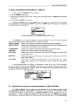
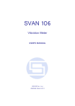
1
SVAN 958 USER MANUAL
8
SETUP MENU - SETUP
The SETUP (path: MENU / SETUP) list contains different windows and positions. Some of them are
directly related with sound measurements, some of them depend on the mode of the instrument (sound or
vibration meter) and some are related with the settings of the instrument’s hardware components. In order
to open the SETUP list the user has to:
• press the <Menu> push-button,
• select from the main list, using the <
>, <
> (or <
>, <
>) push-buttons, the SETUP text (highlight it
inversely),
• press the <ENTER> push-button.
Main list with SETUP text highlighted (displayed inversely)
In the SETUP list the following items are available:
LANGUAGE
it enables the user to set language of the user interface;
CLEAR SETUP
it enables the user to return to the producer’s set-up, except the coefficients
set in the USER FILTERS;
DAY TIME LIMITS
it enables the user to select the hours limiting day and night for the calculation
of the Lden result;
EXT. I/O SETUP
it enables one to connect meter with other device;
KEYBOARD SETUP
it enables the user to set the operating mode of the <Shift> and
<Start / Stop> push-buttons and to switch on the KEYLOCK;
MENU LOCK
it enables the user to lock the menu;
REFERENCE LEVELS
it enables the user to select the reference level for the vibration measurements
and it informs the user about the reference level in the sound measurements;
it enables the user to select the way of integration for the RMS measurement
in the case of vibration meter or the LEQ measurement in the case of sound
level meter;
it enables the user to set the Real Time Clock;
RMS INTEGRATION
RTC
STATISTICAL LEVELS
TIMER
window available only in the sound meter mode. It enables the user to select
ten statistics results to be saved in a file together with the main results
(cf. the description of the files in App. B). This position is taken off from
the menu in the vibration meter mode;
it enables the user to set the Timer function;
USB HOST SETUP
it enables the user to select the functionality of the USB Host port;
USER FILTERS SETUP
it enables the user to select, switch on or off and set the correcting values
for all 1/1 and 1/3 octave filters in the case of sound measurements;
in the case of vibration measurements the weighting filters are always
switched on, the user can set the correcting coefficients;
it enables the user to select the vibration units in which the results
of the measurements are to be given;
it enables the user to switch on or off the warnings, which can be displayed
during the operation of the instrument.
VIBRATION UNITS
WARNINGS
8-1
SVAN 958 USER MANUAL
_
Pressing the <Shift> and <
> (or <Shift> and <
>) push-buttons results in a movement
to the first position of the opened list and pressing the <Shift> and <
> (or <Shift> and <
>) – results
in a movement to the last position of the opened list.
In each available position any change is performed by means of the <
>, <
> push-buttons.
In order to confirm the selection the <ENTER> push-button has to be pressed. After this confirmation
the opened window or list is closed. In order to ignore any changes made in the opened window or list
the user has to press the <ESC> push-button.
Displays with SETUP list
8.1
Setting the language of the user interface - LANGUAGE
The LANGUAGE enables one to select the language of the user interface. In order to enter the list
one has to press the <ENTER> push-button on the inversely displayed LANGUAGE text of the SETUP
list. The selection is made by placing a special character by means of the <
>, <
>, <
>, <
> pushbuttons in the line with the selected language. Pressing the <Shift> and <
> (or <Shift> and <
>) pushbuttons results in a movement to the first position of the opened list and pressing the <Shift> and <
> (or
<Shift> and <
>) – results in a movement to the last position of the opened list. The selection is
confirmed and the list is closed after pressing the <ENTER> push-button. The list is closed without any
confirmation after pressing the <ESC> push-button.
Displays with LANGUAGE list
8.2
Return to the factory made settings - CLEAR SETUP
The CLEAR SETUP (path: MENU / SETUP / CLEAR SETUP) enables the user to return
to the producer’s set-up of the instrument. In order to enter the window the user has to select
the CLEAR SETUP text in the SETUP list, using the <
>, <
> (or <
>, <
>) push-buttons and press
the <ENTER>. After entering this position, the request for the confirmation is displayed. The position is
closed without any action and the instrument returns to the SETUP list after pressing the <ESC> pushbutton.
SETUP list with CLEAR SETUP text highlighted (displayed inversely)
8-2
SVAN 958 USER MANUAL
After entering the window, the request for the confirmation is displayed. The proper answer
for the request is selected by means of the <
>, <
> push-buttons. The instrument returns to the default
set-up after pressing the <ENTER> push-button in the case when the answer YES was chosen.
Displays with the request for the confirmation for CLEAR SETUP execution
During
the
clearing
process,
the
message
“CLEARING SETUP”
is
displayed.
The SETUP CLEARED message is displayed after the return to the default settings and the instrument
waits for the user’s reaction.
Display after the execution of CLEAR SETUP function
The window is closed and the instrument returns to the SETUP list after pressing any push-button
with an exception of the <Shift> and <Alt>.
8.3
Day time limits selection - DAY TIME LIMITS
The DAY TIME LIMITS enables the user to select the required by the local standards determination
of the day and night. These limits are used for the calculation of the Lden function (cf. App. D for
the definition).
In order to enter the window the user has to select the DAY TIME LIMITS text in the SETUP list,
using the <
>, <
> (or <
>, <
>) push-buttons and press the <ENTER>.
SETUP list with DAY TIME LIMITS text highlighted (displayed inversely)
Two options are available: 6H–18H and 7H–19H. The required limits can be selected by means
of the <
>, <
> push-buttons.
The window is closed and the instrument returns to the SETUP list after pressing the <ENTER>
(with the confirmation of a change made in the position) or <ESC> push-button (ignoring any change
made there).
Displays with the available DAY TIME LIMITS
8-3
SVAN 958 USER MANUAL
8.4
_
Selection of the extended mode - EXT. I/O SETUP
The EXT. I/O SETUP (path: MENU / SETUP / EXT. I/O SETUP) enables the user to select
the output or input device. The additional output socket, called EXT I/O, enables one to connect meter
with another device. On this socket, the signal from the input or output of the analogue / digital converter
(before the correction) is available. This signal can be registered using the magnetic recorder, can be
observed on the oscilloscope or can be used for triggering measurements. It is possible to select three
different modes: ANALOG, DIGITAL IN and DIGITAL OUT.
This position enables the user to set the proper parameters of the extended I/O output. In order to
enter the window the user has to select the EXT. I/O SETUP text in the SETUP list, using the <
>, <
>
(or <
>, <
>) push-buttons, and press the <ENTER>.
SETUP list in sound measurements with EXT. I/O SETUP text highlighted (displayed inversely)
In the MODE position of EXT. I/O SETUP window three options are available: ANALOG,
DIGITAL IN and DIGITAL OUT. In order to select the proper mode the user has to press the <
>, <
>
push-buttons. The window is closed and the instrument returns to the SETUP list after pressing
the <ENTER> (with the confirmation of a change made in the window) or <ESC> push-button (ignoring
a change made there).
EXT. I/O SETUP windows with the different I/O devices selection
In the ANALOG mode, the meter can send signals to the output device. For example, the signal
can be observed on the oscilloscope from the selected CHANNEL. The user has the opportunity
to choose between CHANNEL 1, 2, 3 and 4.
The selected channel is being connected to the extended I/O port. In order to enter this position
the user has to select the CHANNEL text in the EXT. I/O SETUP list, using the <
>, <
> push-buttons.
After selection of the CHANNEL the user has to press the <
>, <
> push-buttons. The window is closed
and the instrument returns to the SETUP list after pressing the <ENTER> (with the confirmation of
a change made in the window) or <ESC> push-button (ignoring a change made there).
EXT. I/O SETUP windows with the channel selection for output signal
In the DIGITAL IN mode the meter is connected to the output device, which triggers it.
The measurements are started, when on this input there is a triggering impulse. In this mode
the instrument works in EXT.TRIGGER function.
In the DIGITAL OUT mode the meter is connected to the output device, which has to be triggered.
In this mode the instrument works in TRIGGER PULSE function. It is especially useful in the multichannel, simultaneous, synchronised measurements.
8-4
SVAN 958 USER MANUAL
8.5
Selection of few push-buttons modes - KEYBOARD SETUP
The KEYBOARD SETUP (path: MENU / SETUP / KEYBOARD SETUP) enables one to programme
the operation mode of the <Shift>, <Start / Stop> push-buttons and to set the KEYLOCK option.
SETUP list with KEYBOARD SETUP text highlighted (displayed inversely)
In order to enter the window the user has to select the KEYBOARD SETUP text in the SETUP list,
using the <
>, <
> (or <
>, <
>) push-buttons and press the <ENTER>. The selection of a parameter
in all positions is done by means of the <
>, <
> push-buttons and confirmed by the <ENTER> one.
8.5.1
Selection of the working mode of <Shift> / <Alt> push-buttons - SHIFT MODE
In the SHIFT the user can choose between Shift and 2nd Fun. When the Shift text is selected,
the push-button with this name operates as in the keyboard of a computer – in order to achieve
the desired result the second push-button has to be pushed in conjunction with the <Shift> or <Alt>.
When the 2nd Fun. text is selected the <Shift> push-button operates in the sequence with
the other one. This mode is additionally signalled by the flashing “Arrows” icon on the top of the display
which appears after pressing <Shift> or <Alt> push-button in this mode and is flashing until any other
push-button with double meaning is pressed.
In order to select a desired mode of the <Shift> push-button the <
>, <
> should be pressed.
In order to confirm the selection the <ENTER> push-button has to be pressed. Such pressing closes
the window. After pressing the <ESC> push-button the window is also closed but all changes, which were
made, are ignored.
KEYBOARD SETUP windows with the available settings in SHIFT MODE
8.5.2
Selection of the working mode of <Start / Stop> push-button - START/STOP
In the START/STOP (path: MENU / SETUP / KEYBOARD SETUP) the user can choose between
Normal and Inverse. When the Normal text is selected the <Start / Stop> push-button operates
as it is described in Chapter 2 – the instrument reacts on each of its pressing, starting or stopping
the measurements.
When the Inverse text is selected, the <Start / Stop> push-button operates in conjunction or
in a sequence with the <Shift> one. The measurements are started or stopped after pressing both
push-buttons.
In order to select a desired mode of the <Start / Stop> push-button the <
>, <
> should be
pressed. In order to confirm the selection the <ENTER> push-button has to be pressed. Such pressing
closes the window. After pressing the <ESC> push-button the window is also closed but all changes,
which were made, are ignored.
8-5
SVAN 958 USER MANUAL
_
KEYBOARD SETUP windows with the available settings in START/STOP
8.5.3
Locking the keyboard - KEYLOCK
The KEYLOCK is switched on after placing the special character ([√
√]) in the inversely displayed
position in the line with the KEYLOCK text. In order to confirm the selection the <ENTER> push-button
has to be pressed. Such pressing closes the window. After pressing the <ESC> push-button the window is
also closed but all changes, which were made, are ignored.
KEYBOARD SETUP window with the activation of KEYLOCK option
8.6
Locking the MENU- MENU LOCK
The MENU LOCK (path: MENU / SETUP / MENU LOCK) enables the user to lock MENU partially
or fully. In order to enter the window, the user has to select the MENU LOCK text in the SETUP list, using
the <
>, <
> (or <
>, <
>) push-buttons and press the <ENTER>.
SETUP list with MENU LOCK text highlighted (displayed inversely)
In this window, three options are available NO LOCK, PARTIAL and FULL LOCK. In the case
of default NO LOCK option all available positions in the menu are accessible due to the settings which
were made. The activation of PARTIAL results in locking access to the MENU options, which are
responsible for measurement parameters. In the case of FULL LOCK no one position from the MENU
lists is accessible and after attempt of enter MENU the MENU LOCK window appears on the display.
The MENU is available after unlocking it.
In order to activate the required option the user has to place, by means of the <
>, <
> pushbuttons, the special character [*] in the proper position. In order to confirm the selection, the <ENTER>
push-button has to be pressed. Such pressing closes the window. After pressing the <ESC> push-button
the window is also closed but all changes, which were made, are ignored.
MENU LOCK windows with available options
8-6
SVAN 958 USER MANUAL
8.7
Setting the reference signal in vibration measurements REFERENCE LEVELS
The REFERENCE LEVELS (path: MENU / SETUP / REFERENCE LEVELS) enables the user
to set the reference level of the signal in vibration or sound measurements. The values, which are set
here, are taken into account during the calculations of the measurement results expressed
in the logarithmic scale (with the dB as the units).
In order to enter the window the user has to select the REFERENCE LEVELS text in the SETUP
list, using the <
>, <
> (or <
>, <
>) push-buttons and press the <ENTER>. The selection
of a parameter which level has to be set is done by means of the <
>, <
> push-buttons.
SETUP list with REFERENCE LEVELS text highlighted (displayed inversely)
8.7.1
Setting the reference level of the acceleration signal - ACC
In the ACC, the user can set the reference level of the acceleration signal. It is possible to set
-2
-2
-2
the level from 1 µms to 100 µms with 1 µms step pressing the <
>, <
> push-buttons. The step can
-2
>, <
> push-buttons. In order to confirm
be increased to 10 µms pressing the <Shift> with the <
the setting the <ENTER> push-button has to be pressed. Such pressing closes the window. After pressing
the <ESC> push-button the window is also closed but all changes, which were made, are ignored.
REFERENCE LEVELS windows with the reference level setting of acceleration signal
8.7.2
Setting the reference level of the velocity signal - VEL
In the VEL, the user can set the reference level of the velocity signal. It is possible to set the level
-1
-1
-1
from 1 nms to 100 nms with 1 nms step pressing the <
>, <
> push-buttons. The step can be
-1
increased to 10 nms pressing the <Shift> with the <
>, <
> push-buttons. In order to confirm
the setting the <ENTER> push-button has to be pressed. Such pressing closes the window. After pressing
the <ESC> push-button the window is also closed but all changes, which were made, are ignored.
REFERENCE LEVELS windows with the reference level setting of velocity signal
8.7.3
Setting the reference level of the displacement signal - DIL
In the DIL, the user can set the reference level of the displacement signal. It is possible to set
the level from 1 pm to 100 pm with 1 pm step pressing the <
>, <
> push-buttons. The step can be
increased to 10 pm pressing the <Shift> with the <
>, <
> push-buttons. In order to confirm the setting
8-7
SVAN 958 USER MANUAL
_
the <ENTER> push-button has to be pressed. Such pressing closes the window. After pressing
the <ESC> push-button the window is also closed but all changes, which were made, are ignored.
REFERENCE LEVELS windows with the reference level setting of displacement signal
In the case of sound measurements the REFERENCE LEVELS window is used only to inform
the user that the reference level of the acoustic signal is equal to 20 µPa. After pressing the <ESC> or
<ENTER> push-buttons the window is closed.
REFERENCE LEVELS window with the reference level of the acoustic signal
8.8
Selection of detector’s type in the LEQ (RMS) calculations RMS INTEGRATION
The RMS INTEGRATION (path: MENU / SETUP / RMS INTEGRATION) enables the user to select
the detector type for the calculations of the LEQ function (in the case of sound measurements) or
the RMS function (in the case of vibration measurements). In order to enter the window the user has
to select the RMS INTEGRATION text in the SETUP list, using the <
>, <
> (or <
>, <
>) pushbuttons and press the <ENTER>.
SETUP list with RMS INTEGRATION text highlighted (displayed inversely)
Two options are available: LINEAR and EXPONENTIAL. The required parameter can be selected
by means of the <
>, <
> push-buttons. The window is closed and the instrument returns to the SETUP
list after pressing the <ENTER> (with the confirmation of a change made in the window) or the <ESC>
push-button (ignoring a change made there).
The expressions used for the LEQ or RMS calculations are given in Appendix D. When this option
is selected in the case of sound measurements, the value of the LEQ and SEL function does not depend
on the detector time constant (the results are displayed without the indicator of the detectors selected
in the profiles).
Displays with the available options of RMS INTEGRATION
8-8
SVAN 958 USER MANUAL
When the EXPONENTIAL option is selected in the case of sound measurements, the value
of the LEQ and SEL function depends on the detector time constant (the results are displayed
with the indicator of the detectors selected in the profiles).
8.9
Programming of the instrument’s internal Real Time Clock - RTC
The RTC (path: MENU / SETUP / RTC) enables one to programme the internal Real Time Clock.
This clock is displayed in the top right corner of the instrument’s display. In order to enter the window
the user has to select the RTC text in the SETUP list, using the <
>, <
> (or <
>, <
>) push-buttons
and press the <ENTER>.
SETUP list with RTC text highlighted (displayed inversely)
The operation of the RTC setting is performed in the same way as it was described in the case
of the FILE NAME window. The selection of the setting parameter is performed using the <
>, <
> pushbuttons and the change of its value – using the <
>, <
> push-buttons. The parameter, which value has
to be changed, is flashing.
RTC window
Notice: The new value of a parameter is confirmed after each pressing of the <
>, <
>
(new value is selected without any confirmation from the <ENTER> push-button).
The window is closed and the instrument returns to the SETUP list after pressing the <ENTER> or
<ESC> push-button.
8.10 Selection of statistics levels to be saved in a file - STATISTICAL LEVELS
The STATISTICAL LEVELS (path: MENU / SETUP / STATISTICAL LEVELS) enables the user
to select ten statistics from one hundred calculated in the instrument to be saved in a file together
with the main results of the measurements.
SETUP list with STATISTICAL LEVELS text highlighted (displayed inversely)
8-9
SVAN 958 USER MANUAL
_
In order to enter the window, the user has to select the STATISTICAL LEVELS text in the SETUP
list, using the <
>, <
> (or <
>, <
>) push-buttons and press the <ENTER> one.
STATISTICAL LEVELS windows
The selection of the position in the window (the proper Ni, where i = 1,…, 10) is performed
by means of the <
>, <
> push-buttons. The selection of a number from 1 to 99 in all ten Ni positions
is done by means of the <
>, <
> push-buttons (with the step equal to 1) or by means of the <
>, <
>
push-buttons together with the <Shift> one (with the step equal to 10). The window is closed and
the instrument returns to the SETUP list after pressing the <ENTER> (with the confirmation of all settings
made in the window) or <ESC> push-button (ignoring all settings made there).
8.11 Programming of the instrument’s internal timer - TIMER
The TIMER (path: MENU / SETUP / TIMER) enables one to programme the internal timer.
The instrument can be switched on by itself in the programmed time and can perform the measurements
using the set-up, which was used before its switching off. In order to enter the window the user has
to select the TIMER text in the SETUP list (using the <
> or <
> push-buttons) and press the <ENTER>.
SETUP list with TIMER text highlighted (displayed inversely)
The operation of the TIMER (path: MENU / SETUP / TIMER) setting is performed using the <
>,
<
> push-buttons and the change of its value – using the <
>, <
> push-buttons pressed together with
the <Shift>.
TIMER window
Notice: The new value of a parameter is confirmed after each pressing of the <
> or <
>
together with the <Shift> push-buttons (new value is selected without any confirmation
from the <ENTER> push-button).
The window is closed and the instrument returns to the SETUP list after pressing the <ENTER> or
<ESC> push-button.
8-10
SVAN 958 USER MANUAL
8.12 Selection the USB–HOST port functionality - USB–HOST PORT
The USB–HOST PORT enables one to programme the functionality of the instrument’s socket
named USB Host. This function is under development.
SETUP list with USB–HOST PORT text highlighted (displayed inversely)
The socket USB Host can be used to serve as the input of the different interfaces: RS 232 or USB.
The RS 232 interface in the SVAN 95x instrument is available as a hardware option (a special interface,
named as the SV 55, with a dedicated microprocessor has to be attached to the socket USB Host).
An error occurs in the case of the connection to the socket the peripheral device of the different type than
the selected one.
In order to enter the window the user has to select the USB–HOST PORT text in the SETUP list,
using the <
>, <
> (or <
>, <
>) push-buttons and press the <ENTER> one.
USB–HOST SETUP window
The selection of the socket’s functionality is made with the <
>, <
> (or <
>, <
>) push-buttons
which move the special character between the available options. The selection is confirmed
after pressing the <ENTER> push-button which closes the window and returns to the SETUP list.
The return to this list is also possible after pressing the <ESC> push-button but the selection is not
confirmed. The USB host interface can be used to control the external USB memory disk (USB DISK)
with the FAT16 or FAT32 file systems or IrDA (Infra Red Data Association) interface (USB IrDA) based on
the dedicated circuit STIr4200. The first selection of the USB interface requires the introduction
of the activation code (after pressing the <ENTER> push-button, the ENTER CODE window appears
on the display). The next selection does not require any code.
Displays during the activation of USB host’s functions
Notice: The converter SV 55 serves as the RS 232 interface. The SV 55 connection
to the USB Host socket is detected and after successful detection the headphone icon is switched on.
The transmission using the SV 55 is possible only in the case when the instrument is not connected
to a PC with the USB Device port.
8-11
SVAN 958 USER MANUAL
_
Notice: The USB disk connected to the USB Host socket switches off the instrument’s
internal flash memory. All file functions and remote commands are redirected to the USB disk.
The internal flash memory is activated after the disconnection between USB disk and the instrument.
8.13 Introduction the filter coefficients for 1/1 OCTAVE and 1/3 OCTAVE analysis
– USER FILTERS SETUP
The USER FILTERS SETUP (path: MENU / SETUP / USER FILTERS) enable the user to introduce
the values of the correcting coefficients taken into account in 1/1 OCTAVE or 1/3 OCTAVE analysis.
The results of the analysis can be modified by the introduced factors and so calculated TOTAL values for
one or two active (set to On) sets of the filters presented on the display. In order to enter the window
the user has to select the USER FILTERS SETUP text in the SETUP list, using the <
>, <
> (or <
>,
<
>) push-buttons and press the <ENTER>. The texts which appear after pressing <ENTER> depends
on the position set in the MODE window.
SETUP list with USER FILTERS SETUP text highlighted (displayed inversely)
USER FILTERS SETUP
MODE
• VIBRATION
• SOUND
FILTER
• VUSR1, VUSR2, VURS3 in the case of vibration measurements
• SUSR1, SUSR2, SUSR3 in the case of sound measurements
VIEW
0.80 Hz: available values of 0.8 Hz centre frequency filter: -INF,-100.0dB .. 100.0dB
1.00 Hz: available values of 1 Hz centre frequency filter: -INF,-100.0dB .. 100.0dB
...
…
20.0kHz: available values of 20 kHz centre frequency filter: -INF,-100.0dB .. 100.0dB
EDIT
0.80 Hz: available values of 0.8 Hz centre frequency filter: -INF, -100.0dB .. 100.0dB
1.00 Hz: available values of 1 Hz centre frequency filter: -INF, -100.0dB .. 100.0dB
...
…
20.0kHz: available values of 20 kHz centre frequency filter: -INF, -100.0dB .. 100.0dB
8-12
CLEAR
Are you sure?
SVAN 958 USER MANUAL
8.13.1 Selecting the mode for introduction of user filter coefficients - MODE
In the MODE it is possible to select VIBRATION or SOUND. The selection is made with <
>, <
>
push-buttons.
SPECTRUM BASED windows with MODE selection
8.13.2 Selecting the filter to be viewed, edited or cleared - FILTER
In the FILTER, there are VUSR1, VUSR2, VUSR3 in the case of vibration measurements and
SUSR1, SUSR2, SUSR3 in the case of sound measurements. The selection of a filter is made
with the <
>, <
> push-buttons.
a)
b)
SPECTRUM BASED windows with the filter selection for vibration (a) and for sound (b)
8.13.3 Setting the coefficients of the user filters set - EDIT
After pressing the <ENTER> push-button when the VUSR1 (in the EDIT) text is displayed inversely,
the window containing the status of the selected set and the values of the coefficients for all 1/3 OCTAVE
filters is opened. The status position informs the user that the set is switched on. It is not possible to
change the status.
SPECTRUM BASED windows with EDIT selected
The selection of the position in the set is performed by means of the <
>, <
> push-buttons.
The value is introduced by pressing the <
>, <
> push-buttons. The window is closed and the instrument
returns to the USER FILTERS SETUP window after pressing the <ENTER> (with the confirmation of all
settings made in the window) or <ESC> push-button (ignoring all settings made there).
EDIT windows with the setting of the filter’s coefficient
8-13
SVAN 958 USER MANUAL
_
EDIT windows with the setting of the filter’s coefficient (cont.)
8.13.4 Clearing the coefficients of the user filters - CLEAR
The CLEAR enables the user to clear the values of the user coefficients of the selected octave or
third octave filter. In order to execute the CLEAR operation the user has to highlight the CLEAR text and
press <ENTER>.
SPECTRUM BASED windows with CLEAR selected
The ARE YOU SURE? question appears on the display. The coefficients of a set (or sets) are
cleared after the selection of YES by means of the <
>, <
> push-buttons and after pressing
the <ENTER> one. After clearing the instrument returns to the SPECTRUM BASED window.
Displays with the request for the confirmation for CLEAR FILTER execution
8.14 Selection of the vibration units - VIBRATION UNITS
The VIBRATION UNITS (path: MENU / SETUP / VIBRATION UNITS) enables the user to select
the units for the vibration measurements. In order to enter the window the user has to select
the VIBRATION UNITS text in the SETUP list, using the <
>, <
> (or <
>, <
>) push-buttons and
press the <ENTER>.
SETUP list with VIBRATION UNITS text highlighted (displayed inversely)
2
It is possible to select the METRIC units (e.g. m/s , m/s, m etc.) or NON-METRIC units (e.g. g, ips,
mil etc.). The selection is done by means of the <
>, <
> push-buttons. In order to confirm the selection
the <ENTER> push-button has to be pressed. Such pressing closes the window. After pressing
the <ESC> push-button the window is also closed but all changes, which were made, are ignored.
8-14
SVAN 958 USER MANUAL
VIBRATION UNITS windows
8.15 Warnings selection - WARNINGS
The WARNINGS (path: MENU / SETUP / WARNINGS) enables the user to select the messages
which could be displayed during the operation of the instrument. In order to enter the window the user has
to select the WARNINGS text in the SETUP list, using the <
>, <
> (or <
>, <
>) push-buttons and
press the <ENTER>.
SETUP list with WARNINGS text highlighted (displayed inversely)
8.15.1 Saving the measurement results in a file - RESULTS NOT SAVED
In order to switch on the displaying of the message the user has to place, by means of the <
>,
<
> push-buttons, the special character in the warning’s position. The window is closed and
the instrument returns to the SETUP list after pressing the <ENTER> (with the confirmation of a change
made in the window) or <ESC> push-button (ignoring a change made there).
WARNINGS windows with RESULT NOT SAVE selected
When the position is set to be active the special warning can be displayed on the display after
pressing the <Start / Stop> push-button. It will happen in a case when the result of the previous
measurement was not saved in a file of the instrument. The warning, which will appear on the display, is
presented below.
Displays with the warning that the previous results were not saved and the confirmation
The default value of this position is SAVE NEXT. After pressing <ENTER> the instrument saves
last measurement result. The number of the file is increased by one in the comparison to the last saved
file. Using the <
>, <
> push-buttons one can change the value of the position to YES or NO. To confirm
the change the <ENTER> should be pressed. After the selection of YES the instrument returns
to the active mode of measurement result’s presentation starting the new measurement process.
8-15
SVAN 958 USER MANUAL
_
After the selection of NO push-button the instrument returns to the active mode of measurement result’s
presentation without starting the new measurement process.
8.15.2 Excluding channel from vector calculations - VECTOR SETTINGS
The VECTOR SETTINGS warning appears on the display when the user changes mode
of the channel from VIBRATION into SOUND (path: MENU / INPUT / CHANNELS SETUP / MODE:
VIBRATION 4SOUND) and the channel was included to the vector calculations (path: MENU / INPUT /
AUXILIARY SETUP / VECTOR SETUP / CHANNEL x: [√]).
In order to switch on the displaying of the message the user has to place, by means of the <
>,
<
> push-buttons, the special character in the warning’s position. The window is closed
and the instrument returns to the SETUP list after pressing the <ENTER> (with the confirmation
of a change made in the window) or <ESC> push-button (ignoring a change made there).
WARNINGS windows with the selection of VECTOR SETTINGS
Display with the warning that CHANNEL x has been excluded from vector calculation
8-16