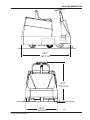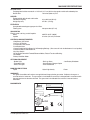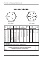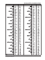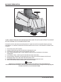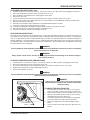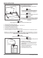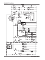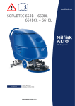
1
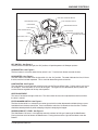
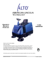
AMERICAN-LINCOLN
TECHNOLOGY
Operator's
Manual &
Parts List
114RS
SWEEPER
Beginning with Serial No. 360498
READ THIS BOOK!
This book has important information for the use and safe operation of this machine. Failure
to read this book prior to operating or attempting any service or maintenance procedure to
your machine could result in injury to you or to other personnel; damage to the machine or to
other property could occur as well. you must have training in the operation of this machine
before using it. If you or your operator (s) cannot read English, have this manual explained
fully before attempting to operate this machine.
ISO 9001
UL
®
#
FILE A2287
All directions given in this book are as seen from the operator's position at the rear of the machine.
1996 American-Lincoln®
Printed in the USA
TABLE OF CONTENTS
MACHINE DIMENSIONS ..................................................................................................................................... 1-3
MACHINE SPECIFICATIONS ............................................................................................................................... 1-4
STANDARD HARDWARE & TORQUE VALUES .................................................................................................. 1-6
DECIMAL-METRIC CONVERSION TABLE .......................................................................................................... 1-7
SAFETY PRECAUTIONS ..................................................................................................................................... 1-8
MACHINE PREPARATION ................................................................................................................................... 1-10
MACHINE CONTROLS ....................................................................................................................................... 1-11
KEY SWITCH ............................................................................................................................................ 1-11
HORN BUTTON ........................................................................................................................................ 1-11
HOUR METER .......................................................................................................................................... 1-11
LIGHT SWITCH ......................................................................................................................................... 1-11
SEAT ADJUSTMENT LEVER .................................................................................................................... 1-11
FILTER SHAKER SWITCH ....................................................................................................................... 1-11
SIDE BROOM LIFT LEVER ....................................................................................................................... 1-11
FOOT PEDAL ............................................................................................................................................ 1-12
WHEEL LOCK .......................................................................................................................................... 1-12
MAIN BROOM LIFT LEVER ....................................................................................................................... 1-13
SIDE BROOM SWITCH ............................................................................................................................. 1-13
BATTERY CONDITION METER ................................................................................................................ 1-13
LOW BATTERY LIGHT .............................................................................................................................. 1-13
DUST CONTROL SWITCH ....................................................................................................................... 1-13
HOPPER RELEASE LATCH ..................................................................................................................... 1-13
EMERGENCY STOP BUTTON (OPTION) ................................................................................................ 1-13
OPERATING INSTRUCTIONS ............................................................................................................................. 1-14
PRE-START CHECKLIST ......................................................................................................................... 1-14
STARTING ................................................................................................................................................. 1-14
POST START CHECKLIST ....................................................................................................................... 1-14
TO TRANSPORT MACHINE ..................................................................................................................... 1-14
TO BEGIN THE CLEANING OPERATION ................................................................................................. 1-14
TO STOP THE CLEANING OPERATION .................................................................................................. 1-15
POST OPERATION CHECKLIST .............................................................................................................. 1-15
TO EMPTY HOPPER ................................................................................................................................ 1-15
HELPFUL HINTS FOR SWEEPING ......................................................................................................... 1-15
SERVICE CHART ................................................................................................................................................ 1-16
SERVICE INSTRUCTIONS .................................................................................................................................. 1-18
MAIN BROOM INSTRUCTIONS ................................................................................................................ 1-18
TO CHECK THE MAIN BROOM SWEEP PATTERN ................................................................................. 1-18
TO ADJUST THE MAIN BROOM SWEEP HEIGHT ................................................................................... 1-18
TO CHANGE THE MAIN BROOM .............................................................................................................. 1-18
SIDE BROOM INSTRUCTIONS ................................................................................................................ 1-19
TO CHECK THE SIDE BROOM SWEEP PATTERN ................................................................................. 1-19
TO CHANGE THE SIDE BROOMS HEIGHT ADJUSTMENT .................................................................... 1-19
TO CHANGE THE SIDE BROOMS ........................................................................................................... 1-19
DUST CONTROL INSTRUCTIONS .......................................................................................................... 1-20
TO CLEAN THE FILTER BAFFLE ............................................................................................................. 1-20
TO CLEAN THE PANEL FILTER ............................................................................................................... 1-20
TO CHANGE THE PANEL FILTER ............................................................................................................ 1-20
FLAP INSTRUCTIONS ............................................................................................................................. 1-21
TO ADJUST THE DRIVE WHEEL AND SIDE FLAPS ................................................................................ 1-21
TO ADJUST THE RECYCLING FLAPS ..................................................................................................... 1-21
BATTERY SERVICE INSTRUCTIONS ...................................................................................................... 1-22
TO CHARGE THE BATTERIES ................................................................................................................. 1-22
TO REMOVE THE BATTERIES ................................................................................................................. 1-22
CONNECTION DIAGRAM .................................................................................................................................... 1-23
SCHEMATIC DIAGRAM ...................................................................................................................................... 1-24
HARDWARE ABBREVIATIONS ........................................................................................................................... 1-25
ORDERING PARTS ............................................................................................................................................. 1-26
American-Lincoln Technology
114 RS Operator’s Manual
1-1
TABLE OF CONTENTS
TABLE OF CONTENTS - CHAPTER 2 ................................................................................................................. 2-1
MAIN BROOM ............................................................................................................................................ 2-2
SIDE BROOMS ......................................................................................................................................... 2-4
DOORS, FLAPS AND SEALS .................................................................................................................. 2-6
SIDE COVER AND BATTERY PAN .......................................................................................................... 2-8
HOPPER ................................................................................................................................................... 2-9
FORWARD/REVERSE PEDAL ................................................................................................................ 2-10
CONSOLE ASSEMBLY ............................................................................................................................. 2-12
FILTER SYSTEM ...................................................................................................................................... 2-14
DRIVE COMPARTMENT AND SEAT ........................................................................................................ 2-16
STEERING AND DRIVE ........................................................................................................................... 2-18
WHEEL LOCK .......................................................................................................................................... 2-20
POWER PANEL ........................................................................................................................................ 2-22
INSTRUMENT PANEL .............................................................................................................................. 2-24
DECALS .................................................................................................................................................... 2-26
TABLE OF CONTENTS - CHAPTER 3 ................................................................................................................. 3-1
BACK-UP ALARM OPTION ......................................................................................................................... 3-2
BATTERY OPTION ................................................................................................................................... 3-4
BROOM OPTION ...................................................................................................................................... 3-5
HEAD AND TAILLIGHT OPTION .............................................................................................................. 3-6
OVERHEAD GUARD OPTION ................................................................................................................. 3-7
AMBER STROBE LIGHT OPTION ........................................................................................................... 3-8
STROBE LIGHT OPTION FOR OVERHEAD GUARD ............................................................................. 3-9
LOW BATTERY SHUTDOWN OPTION .................................................................................................... 3-10
EMERGENCY STOP OPTION .................................................................................................................. 3-11
VAC WAND OPTION ................................................................................................................................. 3-12
SEAT SAFETY SWITCH OPTION .............................................................................................................. 3-14
DRIVE MOTOR SERVICE PARTS ............................................................................................................. 3-16
SPARE PARTS LIST .................................................................................................................................. 3-17
INDEX ............................................................................................................................................................. 3-18
WARRANTY ........................................................................................................................................................ 3-20
1-2
American-Lincoln Technology
114 RS Operator’s Manual
MACHINE DIMENSIONS
56.6"
143.5 cm
47.0"
119.4 cm
American-Lincoln Technology
114 RS Operator’s Manual
36.4"
92.4 cm
C0459
1-3
MACHINE SPECIFICATIONS
SWEEPING PATH
Width
45.0 inches 114.3 cm. Including side brooms
TRAVEL SPEED
Forward
Reverse
4.0 MPH/4.9 KPH
2.0 MPH/2.48 KPH
TURNING RADIUS
Right
Left
U-turn Clearance
46.0 inches116.8 cm.
46.0 inches116.8 cm.
68.00 inches 172.7 cm.
DIMENSIONS
Length
Width
Height
56.6 inches143.5 cm.
36.4 inches 92.4 cm.
47.0 inches119.4 cm.
WEIGHT
Standard Machine
With 228 A.H. Batteries
With 330 A.H. Batteries
686 LBS .311 KGS (Without Batteries)
1071 LBS.486 KGS
1221 LBS.554 KGS
TIRES
Type
Rear
Front
Gray Non-Marking
3.0" wide x 10.0"dia. (7.6cm x 25.4cm) Foam Filled
2.75" wide x 10.0" dia. (7.0 cm x 25.4 cm) Solid
BATTERIES
Two 36 VDC Battery Package Options
228 A.H.
330 A.H.
Qty. 3 - 12 VDC Lead Acid Batteries Total Wt. 384 lb/175 kg
Qty. 6 - 6 VDC Lead Acid Batteries Total Wt. 535 lb/243 kg
DRIVES
Main Broom
Side Brooms
(1) 0.50 HP 36 VDC Electric Motor (372 W.)
(2) 0.13 HP 36 VDC Electric Motor (96.8 W.)
BRAKING
For Operation
For Storage or Service
Dynamic braking to front wheel, using foot pedal.
Hand operated control to engage two rear wheel lock pins.
STEERING
System Type
Steering Wheel Diameter
Steering Angle of Front Wheel
Single front wheel with chain and sprocket column
13 inches (33.02 cm)
180 degrees Available
LUBRICATION
Rear Wheels
Steering Gear
Grease Fittings Provided
Grease Fittings Provided
WHEEL DRIVE SYSTEM
Type
Rating
Front Wheel, Reversible Electric Coaxial Gear Motor
36 VDC .70 HP (500 W.)
MAIN BROOM
Broom bristle mounted in a polycore tube with helical pattern bristle tufted in six double rows.
Length
27.00 inches (68.6 cm)
Broom Size
11.00 inches (27.9 cm) Dia.
Broom bristle Length
3.00 inches (7.6 cm) long. (Usable to 1 Inch Length)
1-4
American-Lincoln Technology
114 RS Operator’s Manual
MACHINE SPECIFICATIONS
SIDE BROOMS
Polypropylene bristles mounted in a 1.25-inch (3.17-cm) thick marine grade varnished hardwood plate.
Broom Size
16 inches (40.6 cm) Dia.
HOPPER
Equipped with dolly wheels and handle.
Volumetric Capacity
Weight Capacity
3.0 cubic feet (85.0 lt)
375 lbs. (170 kg).
FILTRATION
One pleated treated paper type panel air filter.
Filtering area
40 square feet (3.7 m2)
VACUUM FAN
Electric motor is driving a radial impeller.
Motor
Impeller
36VDC .62 HP (462W)
9 inches (22.9 cm) Diameter
CONTROLS AND INSTRUMENTS
-Side Broom “Off” Switch
-Vac Fan “Off” Switch
-Push Button Filter Shaker
-Push Button Horn
-Control Handle for Main Broom Lift & Sweeping Settings. (Also turns off main & side brooms & vac impeller)
-Control Handle for Side Broom Lift
-Key Start Switch
-Single Pedal Control for Forward/Reverse Motion, Rate of Travel and Braking.
-Hour Meter
-Battery Condition Meter
OPTIONAL EQUIPMENT
- Strobe Light
- Emergency Stop
- Head, Tail Lights
- Back-up Alarm
- Low Battery Shutdown
- Smart Battery Charger Option
- Over Head Guard
MAIN BROOM OPTIONS
-Nylon
-Nylon high density
-Proex
WARRANTY
Our general conditions of business are applicable with regard to the guarantee. Subject to change as a
result of technical advances. The guarantee is invalidated if the machine is not operated in accordance with
these instructions or otherwise abused. The guarantee is invalidated if the machine is not serviced as
described.
MACHINE DATA
R
MACHINE NAME
DATE / SERIAL NUMBER
MODEL
RATED POWER
WEIGHT
IP X3
MAX OPERATING SLOPE
LWA
B
American-Lincoln Technology
114 RS Operator’s Manual
1-5
STANDARD HARDWARE & TORQUE VALUES
SAE - Grade 8
SAE - Grade 5
Screw
Size
*6
*8
*10
*1/4
5/16
3/8
7/16
1/2
9/16
5/8
3/4
7/8
1
Grade
5
Plated
C
14
27
39
86
15
28
44
68
98
135
239
387
579
F
15
28
43
108
17
31
49
76
110
153
267
-
Grade
8
Plated
F
C
130
151
22
24
40
44
63
70
95
108
138
155
191
216
338
378
545
818
-
410H
Stainless
C
18
33
47
114
19
34
55
85
-
F
20
35
54
132
22
39
62
95
-
Type
F&T
& BT
Brass
5
9
13
32
6
10
16
-
C
20
37
49
120
-
F
23
41
64
156
-
Type
B, AB
21
34
49
120
-
C = Coarse Thread
F = Fine Thread
* = Torque values for #6 through 1/4 are lb./in. All others are lb./ft.
NOTE
Decrease the torque by 20% when using thread lubricant
The torque tolerance is ± on torque values.
C2000/9905
1-6
American-Lincoln Technology
114 RS Operator’s Manual
DECIMAL METRIC CONVERSION TABLE
FRACTION
DECIMAL
MILLIMETER
FRACTION
DECIMAL
MILLIMETER
C-2001/9907
American-Lincoln Technology
114 RS Operator’s Manual
1-7
SAFETY PRECAUTIONS
THE FOLLOWING STATEMENTS ARE USED THROUGHOUT THIS MANUAL AS INDICATED IN THEIR DESCRIPTIONS:
DANGER
To warn of immediate hazards which will result in severe personal injury or death.
WARNING
To warn of hazards or unsafe practices which could result in severe personal injury or death.
CAUTION
To warn of hazards or unsafe practices which could result in minor personal injury.
ATTENTION
To warn of unsafe practices which could result in extensive equipment damage.
NOTE
To give important information or to warn of unsafe practices which could result in equipment damage.
THE FOLLOWING INFORMATION SIGNALS POTENTIALLY DANGEROUS CONDITIONS TO THE OPERATOR OR EQUIPMENT. READ THIS MANUAL CAREFULLY. KNOW WHEN THESE CONDITIONS
CAN EXIST. THEN, TAKE NECESSARY STEPS TO TRAIN MACHINE OPERATING PERSONNEL.
FOR THE SAFE OPERATION OF THIS MACHINE, READ AND UNDERSTAND ALL WARNINGS, CAUTIONS, AND NOTES.
WARNING
Machines can ignite flammable materials and vapors. Do not use with or near flammables such as: gasoline,
grain dust, solvents, and thinners.
WARNING
Heavy machinery. Improper use can cause personal injury.
WARNING
Operate only when lids, doors, and access panels are securely closed.
WARNING
Use care when reversing machine in confined area.
WARNING
When servicing the machine, disconnect the batteries first to prevent possible injury.
WARNING
When working on the machine, empty hopper, remove batteries, clear area of people and obstructions, and use
additional people and proper procedures when lifting the machine.
WARNING
Always empty the Hopper and Disconnect Battery before doing maintenance.
WARNING
You must have training in the operation of this machine before using it. READ THE INSTRUCTION BOOK.
WARNING
Do not operate this machine unless it is completely assembled.
WARNING
Do not use this machine as a step or furniture.
1-8
American-Lincoln Technology
114 RS Operator’s Manual
SAFETY PRECAUTIONS
WARNING
Be careful when operating the machine on a ramp or incline. Always move slowly on a ramp. Do not turn this
machine on a ramp. Do not stop and leave this machine on a ramp.
WARNING
Stop and leave this machine on a level surface. When you stop the machine, put the power switch in the “OFF”
position and engage the Wheel Lock.
WARNING
To prevent injury, and damage to the machine, do not lift the machine or move it to an edge of a stair or loading
dock.
WARNING
Lead acid batteries generate gases, which can cause an explosion. Keep sparks and flames away from batteries.
NO SMOKING. Charge batteries only in area with good ventilation.
WARNING
Always wear eye protection and protective clothing when working near batteries. Remove all jewelry. Do not put
tools or other metal objects across the battery terminals, or the tops of batteries.
WARNING
Maintenance and repairs must be done by authorized personnel only. Tighten all fasteners. Keep adjustments
according to the specifications given in the service manual for the machine. Keep the electrical parts of the
machine dry. For storage, keep the machine in a building.
WARNING
Make sure that all labels, decals, warnings, cautions and instructions are fastened to the machine. Get new
labels and decals from an Alto American-Lincoln distributor.
WEEE Symbol Information
ENGLISH Correct Disposal of This Product (Waste Electrical & Electronic Equipment)
(Applicable in the European Union and other European countries with separate
collection systems)
This marking, shown on the product or its literature, indicates that it should not be
disposed with other household wastes at the end of its working life. To prevent possible
harm to the environment or human health from uncontrolled waste disposal, please
separate this from other types of wastes and recycle it responsibly to promote the
sustainable reuse of material resources. Household users should contact either the
retailer where they purchased this product, or their local government office, for details
of where and how they can take this item for environmentally safe recycling. Business
users should contact their supplier and check the terms and conditions of the purchase
contract. This product should not be mixed with other commercial wastes for disposal.
American-Lincoln Technology
114 RS Operator’s Manual
1-9
MACHINE PREPARATION
C0458
FIGURE 1
YOUR 114 RS BATTERY MACHINE HAS BEEN SHIPPED COMPLETE, BUT DO NOT ATTEMPT TO OPERATE
WITHOUT READING THE FOLLOWING INSTRUCTIONS.
Uncrate the machine and remove all packing material. Inspect the machine for possible shipping damage.
Install brooms, as outlined in the Service Instructions Section of this manual. Install batteries as follows (if not
included):
1.
2.
3.
4.
5.
6.
7.
8.
9.
Turn the key to the “OFF” position.
Unplug the polarized connector located next to the operator’s seat.
Lift the battery compartment cover and engage the safety latch.
Use a battery-lifting device with a 150 lb. (68 KG) capacity to place the batteries in the battery
compartment.
Install Battery Cables. (See Page 45 for detailed connection information)
Charge batteries (See battery charging procedure in the Service Instructions Section of this Manual)
Disengage battery cover safety latch and carefully lower cover.
Plug the polarized connector into the receptacle located next to the operator’s seat.
READ THIS MANUAL before Attempting to Operate the Sweeper.
WARNING
Hydrogen gas is formed during the charging operation and is explosive! Only charge batteries in a
well-ventilated area with the lid open. Avoid any open flame or electrical sparks. Pulling out the charger plug with
the timer on will cause an arc and must be avoided.
1-10
American-Lincoln Technology
114 RS Operator’s Manual
MACHINE CONTROLS
BATTERY CONDITION METER
SIDE BROOMS LEVER
DUST CONTROL SWITCH
HOUR METER
SIDE BROOMS SWITCH
LIGHT SWITCH
FILTER SHAKER SWITCH
KEY SWITCH
HORN
BATTERY
N
CONDITIO
DUST CON
TROL
ON
WARNING
IN
COULD RESULT
DAMAGE.
MOVEMENT
UNEXPECTEDINJURY OR PROPERTY
PERSONAL
WHEEL LOCK
AND ENGAGESEAT
TO "OFF"
TURN KEYLEAVING OPERATOR'S
BEFORE
OFF
OMS
SIDE BRO
ON
OFF
ON
EMERGENCY STOP BUTTON
MAIN BROOM LEVER
OFF
LOW BATTERY LIGHT
FILTER
SHAKER
ING
OPERAT
WHILE
CHECK
ON
OMS
SIDE BRO
HORN
UP
DOWN
WHEEL LOCK
CB1 CB5
CB4 CB7
CB8
E LOW
VOLTAG
ARE OFF S
BROOMS
ERIE
GE BATT
RECHAR
WHEEL
LOCK
UNLOCK
LOCK
C0461
FIGURE 2
KEY SWITCH - See Figure 2
The Key Switch turned to the right, the “ON” position, will provide power to all Sweeper systems.
HORN BUTTON - See Figure 2
The horn button is active only when the key switch is “on”. Push the horn button to sound the horn.
HOUR METER - See Figure 2
The hour meter is activated when the key switch is in the “On” position. The meter indicates the time, in Hours
that the machine has been operated. This is useful for determining service intervals.
LIGHT SWITCH - See Figure 2
The Light Switch is a push-pull type switch that turns on the Front and Rear Lights. Pull the switch “out” to turn
on the Lights. Push the switch “in” to turn off the Lights. The Lights are not controlled by the key switch and
can be turned on regardless of the key switch position.
SEAT ADJUSTMENT
This lever is located on the right of the seat. This lever allows the seat to be adjusted forward or back when
the lever is moved.
FILTER SHAKER SWITCH - See Figure 2
The filter shaker switch is a momentary on rocker type switch that when depressed and held shakes accumulated debris from the dust control filter. Press and hold the switch for 15 seconds to clear the filter. The filter
should be cleared periodically while sweeping and prior to emptying the hopper.
SIDE BROOMS LIFT LEVER - See Figure 2
The Side Brooms Lift Lever is a two-position control that allows for Lifting or Lowering of the Side Brooms.
Placing the lever to the left lowers the Side Brooms. Placing the lever to the right into the indent raises the
Brooms.
American-Lincoln Technology
114 RS Operator’s Manual
1-11
MACHINE CONTROLS
NEUTRAL
NEUTRAL
FORWARD
REVERSE
P4066
FIGURE 3
FOOT PEDAL-See Figure 3
The accelerator and directional control foot pedal is located on the floor of the operator’s area. The accelerator and
directional control pedal controls the machine direction, travel speed and dynamic braking. If the machine stops due to
an electrical system overload in the power panel controller, allow the pedal to return to the neutral position. Reset is
automatic when the controller cools.
For Forward Travel - Foot pressure on the upper portion of the pedal will cause the Sweeper to move forward. Increase
the foot pressure on the upper portion of the pedal to increase the forward speed.
For Reverse Travel - Put foot pressure on the lower portion of the pedal. The machine will move in reverse. Increase the
foot pressure on the lower portion of the pedal to increase the reverse speed.
To Stop the Sweeper - Allow directional control pedal to return to neutral (center position). Pedal will automatically return
to centered position, which will automatically provide dynamic braking to stop. If Increased Braking action is desired put
light foot pressure to the pedal in the opposite direction of travel until the sweeper stops then allow the pedal to return to
center.
WHEEL LOCK - See Figure 4
E LOW
VOLTAG E OFF
AR
BROOMS
IES
BATTER
GE
AR
RECH
The Wheel Lock is used to prevent unexpected movement
of the machine while it is “Parked” for Storage purposes or
being serviced, such as emptying the hopper. The Wheel
Lock is not to be used as a “Brake.” To engage the wheel
lock, Stop the Sweeper, move the lever out of the indent,
and push it forward. The wheel lock will engage with the
lever in the forward position.
WARNING
WHEEL
LOCK
LOCK
UNLOCK
The Wheel Lock is not to be used as a “Brake.” Make
sure the sweeper has come to a complete stop before
engaging the wheel lock. Personal Injury or Property
Damage Can Result From Using the Wheel Lock as a
“Brake.”
WARNING
C0466
1-12
FIGURE 4
Turn the Key Switch “Off” and engage the Wheel Lock
before Leaving the Operator’s Compartment. Do Not
Leave the Sweeper Unattended.
American-Lincoln Technology
114 RS Operator’s Manual
MACHINE CONTROLS
MAIN BROOM LIFT LEVER - See Figure 5
MAIN BROOM
LIFT LEVER
The main broom lift lever is located on the right side next to
the driver’s seat. To lower the main broom, grasp the lever,
move it to the left to clear the locking notch and pull back to
the first or second notch. The first notch is the “Sweep”
position, which is used for normal sweeping conditions, and
will result in longer broom life. The second notch is the
“Float” position and is used when sweeping very uneven
surfaces. The main broom, side brooms and vacuum fan
will start when the lever is moved from the “Off” position.
MAIN BROOM
OFF
SWEEP
FLOAT
SIDE BROOMS SWITCH - See Figure 2
The Side Brooms Switch is a two-position rocker type On/
Off Switch. Depress the right side of the switch to turn the
side brooms on.
C0467
Depress the left side of the switch to turn the side brooms
off. The side brooms will rotate when the Main Broom
Lever is placed in the Sweep or Float Position.
FIGURE 5
CHARGE BATTERIES
WHEN NEEDLE STAYS IN RED ZONE
WHILE SWEEPER IS BEING OPERATED
BATTERY
CONDITION
- +
BATTERY CONDITION METER - See Figure 6
The meter shows the condition of the battery, while the
machine is running, under load. Batteries are charged
when indicator is in the green zone. When indicator stays
in the red zone, batteries must be charged.
LOW BATTERY LIGHT (OPTION) - See Figure 2
The Low Battery Shutdown prevents excessive discharging
of the batteries. When the batteries get low the indicator
light comes on and the Brooms turn off. When the indicator
light, illuminates Charge the batteries.
DUST CONTROL SWITCH - See Figure 2
C0468
The dust control switch is a two-position rocker switch
located on the right instrument panel and is used to control
operation of the vacuum fan for the dust control system. To
turn on the vacuum fan, push the right side of the rocker
switch. To turn off the vacuum fan push the left side of the
rocker switch. The vacuum fan will only operate when the
main broom lever is moved out of the “Off” position.
FIGURE6
HOPPER RELEASE LATCH - See Figure 7
The Hopper Release Latch is located on the Hopper at the
rear of the sweeper. To disengage the latch, turn the
handle to the left to the nine O’clock positions. The Hopper
is now ready to be removed. To engage the Hopper latch,
ensure the hopper is properly seated and turn the handle to
the right to the three O’clock position. You will feel the latch
engage if the hopper is properly seated.
UNLOCK
LOCK
C0469
LOCK
HOPPER
LATCH
FIGURE 7
American-Lincoln Technology
114 RS Operator’s Manual
EMERGENCY STOP BUTTON (OPTION) - See
Figure 2
The emergency stop button is a Red Mushroom switch,
which is located near the key switch. To quickly shut down
power to the machine, push the large red button. To reset
the shut down button; first turn the red button clockwise in
the direction of the arrows marked on the switch. Now turn
the key switch to the “Off” position then clockwise to the
“start” position, when you release the key switch and allow
it to return to the “On” position the Sweeper will operate.
1-13
OPERATING INSTRUCTIONS
1,2
6
3
114
RS
4
C0470
5
FIGURE 8
NOTE
Before starting, perform the pre-start checks.
PRE-START CHECKLIST - See Figure 8
1. Check controls for proper operation
2. Make sure all controls are in the “Off” position
3. Be sure accelerator / directional control pedal is in the neutral position.
4. Check all Dust flaps for damage or wear.
5. Check Main Broom and Side Broom for proper broom pattern.
6. Ensure that the hopper latch is properly engaged.
TO START MACHINE
1. Release the Wheel Lock.
2. Turn key to “On” position.
POST START CHECKLIST
1. Check the Battery Condition Meter for sufficient battery charge. This must be done with the machine
running.
TO TRANSPORT MACHINE
1. Be sure the Main Broom and Side Broom Controls are in the “UP” or “OFF” position with all other controls
in the “OFF” position.
2. Push forward on the directional control pedal to place the machine in motion.
3. Vary your foot pressure on the directional control pedal to obtain desired travel speed.
4. To stop, allow directional control pedal to return to neutral (centered) position. (Pedal will automatically
return to neutral when foot pressure is released).
TO BEGIN SWEEPING
1. Lower the Side Brooms by Moving the Side Broom Lift Lever to the “Down” Position.
2. Turn on the Side Brooms by setting the side brooms switch to the “On” Position.
3. Turn on the Dust control system by setting the Dust Control Switch to the “On” position.
4. Move the broom lift lever to the “Sweep” or “Float” position.
5. Vary your foot pressure on the directional control pedal to obtain desired travel speed.
6. To stop, allow directional control pedal to return to neutral (centered) position. (Pedal will automatically
return to neutral when foot pressure is released).
1-14
American-Lincoln Technology
114 RS Operator’s Manual
OPERATING INSTRUCTIONS
SIDE AISLES
MAIN AISLE
P4134/0001
P4134
SIDE AISLES
FIGURE 9
HELPFUL HINTS FOR SWEEPING - See Figure 9
Here are some suggestions to keep in mind while sweeping.
1. Plan your sweeping in advance. Try to arrange long runs with minimum stopping and starting.
2. Pick up large debris before sweeping with the Machine.
3. Use the sweeper to sweep debris from side aisles into the main aisle.
4. After the Sweeper has made a sweeping run, turn off the dust control switch and use the filter shaker,
Push and hold the shaker switch for approximately 15 seconds
5. Allow a few inches of overlap of sweep paths. This will eliminate leaving dirty patches.
6. Sweep in straight paths and do not bump posts or scrape the sides of the machine.
7. Periodically turn the sweeping broom end for end to prevent the bristles from “setting” in one direction.
8. Do not turn steering wheel too sharply when machine is in motion. The machine is very responsive to
movement of the steering wheel - so avoid sudden turns.
9. As the Hopper becomes full, the sweeper will start to leave debris on the floor. When this occurs stop
sweeping and empty the hopper.
TO EMPTY THE HOPPER
1. Place the Main Broom Lever in the “Off” position, raise Side Brooms, and proceed to the disposal site for
emptying the Hopper.
2. Stop the Sweeper, Turn off the dust control switch and shake the filter for 15 seconds.
3. Place all controls in the “Off ” position and engage the wheel Lock.
4. Proceed to the rear of the Sweeper and unlock the Hopper latch.
5. Grasp the Hopper Handle and remove the hopper.
6. Dump the Hopper. Get Help if needed.
7. Position the Hopper and install it making sure that the Hopper goes in squarely.
8. Lock the Hopper Latch.
9. Resume Sweeping or perform the Post Operation Checklist if finished Sweeping.
TO STOP THE SWEEPING OPERATION
When the sweeping has been completed follow these instructions.
NOTE
After stopping, perform these post operation checks.
POST OPERATION CHECKLIST
1. Before turning off key switch, Check Battery Condition Meter.
2. Stop Machine and turn key switch to “Off” and Engage Wheel Lock.
3. Check all flaps for wear, damage, and adjustment.
4. Empty Hopper
5. Check Main Broom and Side Broom for wear or damage.
6. Charge Batteries if determined to be necessary in step 1 above.
American-Lincoln Technology
114 RS Operator’s Manual
1-15
SERVICE CHART
5
8
7
2
BATTERY
CONDITION
ROL
DUST CONT
ON
WARNING
IN
COULD RESULT
DAMAGE.
MOVEMENT
UNEXPECTEDINJURY OR PROPERTY
PERSONAL
WHEEL LOCK
AND ENGAGESEAT
TO "OFF"
TURN KEYLEAVING OPERATOR'S
BEFORE
OFF
MS
SIDE BROO
OFF
ON
ON
OFF
ER
SHAK
FILTER
ON
K WHIL
CHEC
SIDE BROO
HORN
MS
ATING
E OPER
UP
DOWN
CB1 CB5
CB4 CB7
CB8
LOW
VOLTAGE OFF
ARE
BROOMS BATTERIES
RECHARGE
12
7
WHEEL
LOCK
UNLOCK
4
LOCK
9
3,10
13
1
7
6,11
C0474
C0474
FIGURE 10
SERVICE CHART FOR 114 RS
Check items for proper operation. If service is required, please consult your Clarke/American-Lincoln Authorized
Distributor:
EVERY 8 HOURS or DAILY
1. All flaps for wear or damage.
2. Wheel Lock for proper operation.
3. Main Brooms for wear or damage.
4. Side Brooms for wear or damage.
5. Check Batteries and charge if necessary. (See Page 22 for Battery charging instructions)
6. Empty Hopper and ensure latch is properly secured.
7. All Hardware, Panels and Covers for tightness and security
50 HOUR MAINTENANCE CHECKLIST
8. Check battery electrolyte level.
9. Lubricate front wheel bearing and pivot.
10. Rotate Main Broom end for end to prevent uneven wear.
100 HOUR MAINTENANCE CHECKLIST
11. Clean Hopper.
12. Remove and Clean / Inspect Dust Control Filter. Replace if necessary
13. Lubricate Wheel lock pins.
1-16
American-Lincoln Technology
114 RS Operator’s Manual
SERVICE CHART
For service assistance, consult your local Alto American-Lincoln Distributor. For best performance, replace worn
parts with genuine American-Lincoln parts.
Refer all Maintenance and Service Requirements to Qualified Maintenance Personnel.
Do not attempt to Service this Machine until you have read and understand all Safety Warnings associated
with the equipment you are working with.
WARNING
Electrical repairs must be done by authorized personnel only. Consult your American-Lincoln Authorized Service
Person to do service procedures. Use only genuine American-Lincoln parts.
WARNING
Always park on a level surface, turn key off, and engage wheel lock before working on the machine to keep it
from creeping or rolling.
IMPORTANT
If towing or pushing is required, disconnect motor lead located on the terminal block on the bottom of the
machine
WARNING
Maintenance and repairs must be done by authorized personnel only. Always empty the Hopper and disconnect
the batteries before doing any maintenance. Keep all fasteners tight. Keep adjustments according to the
specifications as shown in the Service Manual for this machine.
WARNING
Always wear eye protection and protective clothing when working near batteries. Do not put tools or other metal
objects across the tops of the batteries. NO SMOKING.
WARNING
To prevent damage to the machine and discharge across the tops of the batteries, do not fill the batteries above
the bottom of the tube in each cell. Wipe any acid from the machine or the tops of the batteries. Do not add acid
to a battery after installation.
WARNING
Always engage the safety latch before working under the Battery cover.
WARNING
Turn Key Off Before removing Battery Connector. Disconnecting the Battery with the key switch on will produce
sparks and Could cause an Explosion.
American-Lincoln Technology
114 RS Operator’s Manual
1-17
SERVICE INSTRUCTIONS
2
4
1
C0477a
3
FIGURE 11
MAIN BROOM SERVICE INSTRUCTIONS
TO CHECK THE MAIN BROOM SWEEP PATTERN
Check the main broom sweep pattern after changing the broom or when poor sweeping performance is encountered
while sweeping.
1. While the machine is not moving, lower the main broom to the SWEEP position and let machine sweep in one spot
for a short period.
2. Before moving machine, move main broom lever to the OFF position and move the sweeper forward until you can
see the pattern left by the main broom bristles on the floor.
3. Check the width of the pattern on the floor to determine if the main broom requires adjustment.
- A normal sweep pattern left on the floor will be between one and two inches wide.
- A pattern that is more than two inches wide indicates the broom linkage needs to be adjusted “UP.”
- A pattern that is less than one inch wide indicates the broom linkage needs to be adjusted “DOWN.”
WARNING
Always engage the safety latch before working under the Battery cover.
TO ADJUST THE MAIN BROOM SWEEP HEIGHT
When changing the sweep height adjustment it is recommended that the bolt be adjusted one turn at a time, After
adjustment, recheck the sweep pattern to determine if further adjustment is necessary.
1. Gain access to the main broom height adjustment bolt by lifting the battery compartment cover, locking it in the up
position and removing the right side panel cover.
2. Locate the Main Broom Height Adjustment bolt, which is located at the bottom of the Main Broom Lift linkage.(It will
have a spring around it)
3. Turn the adjustment screw as described below.
-Turn the adjustment bolt counterclockwise to INCREASE the sweep pattern width.
-Turn the adjustment screw clockwise to DECREASE the sweep pattern width.
WARNING
Always park on a level surface, turn key off, and engage wheel lock before working on the machine to keep it
from creeping or rolling.
TO CHANGE THE MAIN BROOM [See Figure 11]
Replace the main broom when the bristles become worn to 1-inch length.
1. Park the sweeper on a smooth level surface and engage the wheel lock.
2. Gain access to the main broom by opening the left-hand side broom compartment door.
3. Remove the Main broom Idler hub [Item 2] by loosening the threaded knob [Item 1].
4. Grasp the Main Broom [Item 3] and remove it from the drive hub. [Item 2].
5. Insert Replacement Broom [Item 3] Into the broom compartment. Pay special attention to the slots on the broom, it
may be necessary to rotate the broom so the tabs on the drive hub align with the slots on the broom.
6. Reinstall the idler hub [Item 2] to the broom and over the locator stud [Item 4] and screw provided for the threaded
knob [Item 1].
7. Install the threaded knob and close the Broom Door.
8. Recheck Main Broom Sweep Pattern.
1-18
American-Lincoln Technology
114 RS Operator’s Manual
SERVICE INSTRUCTIONS
FLOOR
CONTACT
AREA
FLOOR
CONTACT
AREA
C0472
FIGURE 12
SIDE BROOMS SERVICE INSTRUCTIONS
The Side Brooms Sweeping angle is not adjustable however the height of the side brooms can be adjusted to
compensate for wear as the brooms become worn from use. Two access panels need to be removed to make
the Side Broom Height adjustment.
TO CHECK THE SIDE BROOM SWEEP PATTERN
1. Park the machine on a smooth level surface and turn the Side Broom Switch to the “ON” position.
2. Place the Side Broom Lift Lever in the “DOWN” position.
3. Move the Main Broom Lever to the “SWEEP” position.
4. While staying in place, allow the side brooms to sweep for a short period. (Allow enough time for the side
brooms to leave a clean footprint on the floor).
5. Place the Side Broom Lift Lever in the “UP” position.
6. Turn the Side Broom Switch to the “OFF” position.
7. Move the Main Broom Lever to the “OFF” Position.
8. Back the sweeper away from the area where the Pattern was left.
9. Turn Key Switch to the “OFF” position and engage Wheel Lock.
10. Leave operator’s compartment and check the Pattern to determine the Floor Contact area.
11. Determine if adjustment to the side brooms height is necessary by comparing the floor contact area to the
diagram in figure 12.
WARNING
Always park on a level surface, turn key off, and engage wheel lock before working on the machine to keep it
from creeping or rolling.
TO CHANGE THE SIDE BROOMS HEIGHT ADJUSTMENT
1. Park Machine on a smooth level surface, turnkey switch to “OFF” Position and engage Wheel Lock.
2. Place the Side Brooms Lift Lever in the “DOWN” Position.
3. Remove the two access panel screws and remove panel.
4. Loosen the four bolts that pass through the slots in the side broom motor lift bracket.
5. Lower the side broom motor in the slots so the broom contacts the floor as shown. (See figure 12)
6. Tighten the four bolts and recheck the sweep pattern.
7. Reinstall the access panels when proper adjustment has been achieved.
TO CHANGE THE SIDE BROOMS
Change the side brooms when the bristles become worn to less than 3 inches length.
1. Park Machine on a smooth level surface, turnkey switch to “OFF” Position and engage Wheel Lock.
2. Place the side brooms lever in the “DOWN” Position.
3. Remove the three (3) ¼ inch bolts and nuts that hold the broom to the motor flange.
4. Install the replacement Broom and fasten using the hardware removed in step 3.
American-Lincoln Technology
114 RS Operator’s Manual
1-19
SERVICE INSTRUCTIONS
DUST CONTROL SYSTEM SERVICE INSTRUCTIONS
The Dust Control system consists of a Filter Baffle and a Panel Filter. The filter baffle is located under the dust control
filter and should be checked/cleaned when the hopper is being emptied. The Panel Filter is located in the rear compartment behind the seat.
WARNING
Always park on a level surface, turn key off, and engage wheel lock before working on the machine to keep it
from creeping or rolling.
TO CLEAN THE FILTER BAFFLE
The filter baffle should be cleaned as a first step when the dust control system fails to effectively control dusting while
sweeping.
1. Park the sweeper on a smooth level surface, Turn the key switch to the “OFF” position and engage the wheel lock.
2. Disconnect the Battery Connector, which is located next to the seat.
3. Remove the hopper.
4. Lower the baffle and inspect for debris lodged in the baffle passages.
5. Dislodge all debris from the baffle manually or with compressed air not to exceed 100 PSI.
6. Raise the baffle. Making sure the baffle “Locks” into place.
7. Reinstall the hopper.
8. Reconnect the Battery and return the Sweeper to service.
WARNING
Always engage the safety latch before working under the Battery cover.
WARNING
Turn Key Off Before removing Battery Connector. Disconnecting the Battery with the key switch on will produce
sparks and Could cause an Explosion.
TO CLEAN THE PANEL FILTER
Clean the Panel filter when the shaker fails to adequately clear the filter pleats.
(Refer to page 39 for detailed assembly drawing)
1. Park the sweeper on a smooth level surface, Turn the key switch to the “OFF” position, and engage the wheel lock.
2. Disconnect the Battery Connector, which is located next to the seat.
3. Raise the Battery compartment cover and engage the safety latch.
4. Remove the rear cover.
5. Locate and remove the four wing nuts that hold the filter manifold assembly in place over the filter.
6. Disconnect the shaker motor leads and the Vac fan leads and lift the Vac Fan/Manifold assembly off thedust filter.
7. Remove the filter and blow the dust off the filter with compressed air not to exceed 100 PSI
8. Reinstall the cleaned filter and assemble the Vac Fan/Manifold Assembly to the filter.
9. Connect the shaker motor leads and the Vac fan leads.
10. Install the four Wing Nuts and tighten enough to lightly compress the gasket on the filter.
11. Reinstall the Rear cover and lower the Battery Compartment cover.
12. Reconnect the Battery and return the Sweeper to service.
WARNING
Always engage the safety latch before working under the Battery cover.
WARNING
Turn Key Off Before removing Battery Connector. Disconnecting the Battery with the key switch “on” will
produce sparks and Could cause an Explosion.
WARNING
Always park on a level surface, turn key off, and engage wheel lock before working on the machine to keep it
from creeping or rolling.
TO CHANGE THE PANEL FILTER
Change the filter when obvious damage is evident, Inspect for leakage or a heavily loaded filter to the point that cleaning
and shaking of the filter has no effect on clearing the pleats.
1-20
American-Lincoln Technology
114 RS Operator’s Manual
SERVICE INSTRUCTIONS
TO CHANGE THE PANEL FILTER - Cont.
1.
2.
3.
4.
5.
6.
7.
8.
9.
10.
11.
12.
Park the sweeper on a smooth level surface, Turn the key switch to the “OFF” position and engage the wheel lock.
Disconnect the Battery Connector, which is located next to the seat.
Raise the Battery compartment cover and engage the safety latch.
Remove the rear cover.
Locate and remove the four wing nuts that hold the filter manifold assembly in place over the filter.
Disconnect the shaker motor leads and the Vac fan leads and lift the Vac Fan/Manifold assembly off thedust filter.
Remove and replace the dust filter.
Reinstall the cleaned filter and assemble the Vac Fan/Manifold Assembly to the filter.
Connect the shaker motor leads and the Vac fan leads.
Install the four Wing Nuts and tighten enough to lightly compress the gasket on the filter.
Reinstall the Rear cover and lower the Battery Compartment cover.
Reconnect the Battery and return the Sweeper to service.
FLAP SERVICE INSTRUCTIONS
The Flaps are very important to the sweeping process. Inspect the Flaps Daily and replace any flap that shows signs of
wear or deterioration. The drive wheel and side flaps are adjustable and should be adjusted so there is a recommended
1/16" to 1/8" gap between the floor and the bottom edge of the flaps. The adjustable flaps have slotted mounting holes to
facilitate adjustment. The Recycling flap is also an adjustable flap and should be adjusted so the flap touches the broom.
The adjustment bolt is located inside the left side broom chamber door. All other flaps require no adjustment and should
be replaced when worn or damaged.
WARNING
Turn Key Off Before removing Battery Connector. Disconnecting the Battery with the key switch on will produce
sparks and Could cause an Explosion.
WARNING
Always park on a level surface, turn key off, and engage wheel lock before working on the machine to keep it
from creeping or rolling.
TO ADJUST THE DRIVE WHEEL AND SIDE FLAPS
1.
2.
3.
4.
5.
Park Sweeper on a smooth level surface. Turn the key switch to the “OFF” position and engage the wheel lock.
Disconnect the Battery Connector located next to the seat.
Loosen the Flap retaining screws and adjust the flap to clear the floor and leave a 1/16" to 1/8" Gap.
Tighten Flap retaining screws while holding flap in position.
Reconnect the Battery Connector.
WARNING
Turn Key Off Before removing Battery Connector. Disconnecting the Battery with the key switch on will produce
sparks and Could cause an Explosion.
WARNING
RECYCLING FLAP
Always park on a level surface, turn key off, and engage
wheel lock before working on the machine to keep it from
creeping or rolling.
TO ADJUST THE RECYCLING FLAP
1.
2.
3.
4.
5.
FLAP ADJUSTMENT
SCREW
C0477b
6.
Park Sweeper on a smooth level surface. Turn the key
switch to the “OFF” position and engage the wheel lock.
Disconnect the Battery Connector located next to the seat.
Open the left side broom door and locate the recycling
flap adjustment screw (See Figure 13)
Loosen the adjustment screw and turn the flap upwards
so the flap touches the ends of the broom bristles.
Tighten the adjustment screw while holding the flap in
place.
Close and Latch the left side broom door Reconnect the
Battery.
FIGURE 13
American-Lincoln Technology
114 RS Operator’s Manual
1-21
SERVICE INSTRUCTIONS
SAFETY
LATCH
BATTERY SERVICE INSTRUCTIONS
TO CHARGE THE BATTERIES
1. Ensure Wheel Lock is engaged and key switch is
“Off”.
WARNING
Turn Key Off Before removing Battery Connector.
Disconnecting the Battery with the key switch on will
produce sparks and Could cause an Explosion.
WARNING
Always wear eye protection and protective clothing when
working near Batteries.
WARNING
C0471
FIGURE 14
Remove all Jewelry and do not lay tools etc. across the
tops of Batteries. Batteries produce Explosive Hydrogen
Gas. Keep Sparks and Flames away from Batteries.
NO SMOKING.
WARNING
Always engage the safety latch before working under the Battery cover.
2.
3.
4.
5.
6.
7.
8.
Disconnect Machine Battery Connector.
Raise Battery Cover and engage Safety Latch. (See Figure 14)
Insert charging plug into battery receptacle.
Plug power cord into proper AC source.
Leave battery cover open while charging.
Follow the charging instructions provided on the Charger.
Maintain electrolyte level in batteries check after charging. Add distilled water as needed (See Figure15)
WARNING
Hydrogen gas is formed during the charging operation and is explosive! Only charge batteries in a well-ventilated area with the lid open. Avoid any open flame or electrical sparks. Pulling out the charger plug with the
Charger on will cause an arc and must be avoided.
WARNING
Batteries are heavy. Use two people to lift the batteries.
WARNING
Always engage the safety latch before working under the
Battery cover.
DISTILLED WATER
FILL TO 1/4 INCH
FROM BOTTOM OF TUBE
1/4 INCH (6mm)
P4074
1-22
TO REMOVE THE BATTERIES
1. Turn Key Switch “Off” and engage the wheel lock.
2. Unplug the battery connector located next to the
operator’s seat.
3. Raise the battery compartment cover and engage
the Safety Latch.(See Figure 14)
4. Disconnect the Battery Cables.
5. Lift the Batteries out one at a time.
FIGURE 15
American-Lincoln Technology
114 RS Operator’s Manual
CONNECTION DIAGRAM
25
9B
25B
25A
25C
9
CB-1.
CB-4
CB-5
16B
CB-8
CB-7.
OPTION
15A
21
16C
17A
H-SW.
17
16D
26
20
9B
16C
I
7L
SM-SW.
15
15A
16A
7G
L-SW.
25 K-SW.
1
17A
16B
7M
HM
A B
SB-SW.
7L 7H
19
CM
WSB-SW.
POT
10
26
HORN
12
7M
11
BLK.
AFTER TERMINATING CONNECTORS "C" & "D",
TAPE WITH 1&1/2 WRAPS OF ELECTRICAL TAPE.
7H
MTR..
RED
22
RT. SIDE BROOM.
15
12
11
10
9
CON. A F
E
D
C
B
15
12
11
10
9
A
1
7G
17
22
21
20
19
16A
CON. C
CON. D
F
E
D
C
B
A
1
7G
17
22
21
20
19
16A
TB-3
A1.
BROOM
MTR..
A2
TOP TERMINAL.
7E
14
WHT.
8
13
BLK.
MTR..
CB-2
CB-6
CB-3
DRIVE
5
TB-4
7J
16A
CON. B
RED
1
MTR..
BLK.
LEFT SIDE BROOM
22A
1A
16
1C
2
6
1B
BROOM SW.
7G 7E
TB -2
36 VOLT
BATTERY
BANK
7K
7
1C
1B
TB-1
1A
SOL. 3
D5
SOL.1A
SOL. 2
SOL. 4
5A
5
22
21
6
8
3
2
22A
19
7D
20
7C 7D
16
7B
7F
17
7C
7A
9
7B
7K
10
7F
MTR.
VACUUM
11
13
12
14
3
7
7A
15
12 3
P1
MTR.
6 12
P2
M2 M1
B+
B-
SHAKER
9A
C0465/9812
American-Lincoln Technology
114 RS Operator’s Manual
CONTROLLER
1-23
SCHEMATIC DIAGRAM
36V BATTERY BANK
CC
CC
1A
1B
1C
CB-2
20A
1B
MAIN BROOM
8
6
2A
CB-3
25A
1,1A
MTR.
A2
5A
5
VACUUM
MTR.
3A
7E
A1
7K
D5
CB-6
35A
1C
7
2
CB-1
10A.
9B
9
9
4
20A.
WHT.
DRIVE.
7A,7B
1A.
14
BLK.
D1.
11
1
2
10
5
MTR.
1
M1
9A
Note: 9A jumper is
NOT USED
with seat switch option
M2
6
12
EMERG. STOP
1
1203A
CONTROLLER
BB+
MTR.
13
2
4
3
7,7A
3
3
1A
3
P1
2
1
Seat Sw
Option
20A
25
KEY
SWITCH
5
21A
LOW BATTERY
SHUT DOWN
OPTION
TD-1.
CB-5
10A
16A,16B
25 3
25A
(+)
16B
16C
(+)
16C,16D
CM.
HM.
(-)
7G,7H,7L,7M
(-)
7L
HORN.
HORN
SWITCH
16D
BROOM
SWITCH.
16,17
16
16A
TD-1
7M
26
HELD OPEN
IN THE UP POSITION
17A
7B,7C
2A
WSB
SW.
D2
17,17A SB -SW.
21
4A
D3
7C,7D
SIDE BROOM
SOL.
D4
RED
4A
25A
25B
20
RT.
22
22,22A
7D,7K
3A.
LOW BATTERY
SHUT DOWN OPTION
TD-1
CB-4
10A
19
MTR.
BLK.
7H
7G
7H
LT.
22A
SHAKER MTR.
SW..
CB-7
10A
15A
BLK.
15
25B
25C
MTR.
RED
MTR.
36V
SHAKER
7J
7F
RT. HEAD LIGHT
OPTIONS
LT.. HEAD LIGHT
1
RT. TAIL LIGHT
LIGHT
SWITCH
LT. TAIL LIGHT
2
CB-8
10A
BEACON LIGHT (STROBE 0NLY)
25C
FOOT PEDAL
CLOSED IN REVERSE.
CB-9
25 A
BACK UP ALARM
VACUUM WAND SW.
MTR.
1-24
VACUUM
American-Lincoln Technology
114 RS Operator’s Manual
HARDWARE ABBREVIATIONS
ABBREVIATIONS - SCREWS
ADJ
ADJ.SP
BHM
BHS
CAPT.SL
CAPT.WG
FHM
FIL.HM
HHC
HHM
HIHD
HSHC
HSFHC
KNH
MHHC
PHM
RHD
RHM
RHW
SHC
SHTB
SQ
TB
THM
WELD
WG
=
=
=
=
=
=
=
=
=
=
=
=
=
=
=
=
=
=
=
=
=
=
=
=
=
=
Adjusting Screw
Adjusting Plunger Screw
Binding Head Machine Screw
Button Head Socket Screw
Captivated Slotted Screw
Captivated Wing Screw
Flat Head Machine Screw
Filister Head Machine Screw
Hexagon Head Cap Screw
Hexagon Head Machine Screw
1/2 High Head Screw
Hexagonal Socket Head Cap Screw
Hexagonal Socket Flat Head Cap Screw
Knurled Head Screw
Metric Hexagon Head Cap Screw
Pan Head Machine Screw
Round Head Drive Screw
Round Head Machine Screw
Round Head Wood Screw
Shiny Crown Cap Screw
Shoulder Thumb Screw
Square Head Screw
Thumb Screw
Truss Head Machine Screw
Weld Stud
Wing Screw
ABBREVIATIONS - SETSCREWS
HS
S
SH
-KCP
-CP
-OP
-FDP
-HDP
-FP
-COP
=
=
=
=
=
=
=
=
=
=
Hexagonal Socket Setscrew
Slotted Setscrew
Square Head Setscrew
Knurled Cup Point Setscrew
Cup Point Setscrew
Oval Point Setscrew
Full Dog Point Setscrew
Half Dog Point Setscrew
Flat Point Setscrew
Cone Point Setscrew
C-2004
American-Lincoln Technology
114 RS Operator’s Manual
1-25
ORDERING PARTS
INTERNET
http://www.alto-online.com
ALTO HEADQUARTERS
Incentive International A/S
Kongens Nytorv 28
P.O. Box 2064
1013 Copenhagen K
Tel.: +45 72 18 10 00
Fax: +45 72 18 11 64
E-mail: [email protected]
SUBSIDIARIES
AUSTRALIA
ALTO Overseas Inc.
1B/8 Resolution Drive
P.O. Box 797
Caringbah, N.S.W.2229
Tel.: +61 2 95 24 61 22
Fax: +61 2 95 24 52 56
AUSTRIA
ALTO Österreich GmbH
Metzgerstr. 68
5101 Bergheim/Salzburg
Tel.: +43 6624 5 64 00-14
Fax: +43 6624 5 64 00-55
E-mail: [email protected]
BRAZIL
Wap do Brasil Ltda.
Rua 25 de Agosto, 608
83323-260 Pinhais/Paraná
Tel.: +55 4 12 10 67 40 0
Fax: +55 4 12 10 67 40 3
E-mail: [email protected]
CZECH REPUBLIC
ALTO Ceská Republika s.r.o.
Zateckych 9
14000 Praha 4
Tel.: +420 2 41 40 84 19
Fax: +420 2 41 40 84 39
E-mail: [email protected]
Web: www.wap-alto.cz
DENMARK
ALTO Danmark A/S
Industrikvarteret
9560 Hadsund
Tel.: +45 7218 21 00
Fax: +45 7218 21 05
E-mail: [email protected]
FRANCE
ALTO France S.A.
B.P. 44, 4 Place d’Ostwald
67036 Strasbourg Cedex 2
Tel.: +33 3 88 28 84 00
Fax: +33 3 88 30 05 00
E-mail: [email protected]
GERMANY
ALTO Deutschland GmbH
Guido-Oberdorfer-StraBe 2-8
89287 Bellenberg
Tel.: +49 0180 5 37 37 37
Fax: +49 0180 5 37 37 38
E-mail: [email protected]
GREAT BRITAIN
ALTO Cleaning Systems
(UK) Ltd.
Bowerbank Way
Gilwilly Industrial Estate, Penrith
Cumbria CA11 9BN
Tel.: +44 1 7 68 86 89 95
Fax: +44 1 7 68 86 47 13
E-mail: [email protected]
CANADA
ALTO Canada
24 Constellation Road
Rexdale, Ontario M9W 1K1
Tel.: +1 416 6 75 58 30
Fax: +1 416 6 75 69 89
NETHERLANDS
ALTO Nederland B.V.
Postbus 65
3370 AB Hardinxveld-Giessendam
Tel.: +31 18 46 77 20 0
Fax: +31 18 46 77 20 1
E-mail: [email protected]
CROATIA
Wap ALTO Strojevi za ciscenje, d.o.o.
Siget 18a
10020 Zagreb
Tel.: +385 1 65 54 144
Fax: +385 1 65 54 112
E-mail: [email protected]
NORWAY
ALTO Norge A/S
Bjørnerudveien 24
1266 Oslo
Tel.: +47 22 75 17 70
Fax: +47 22 75 17 71
E-mail: [email protected]
SINGAPORE
ALTO DEN-SIN Singapore Pte Ltd.
No. 17 Link Road
Singapore 619034
Tel.: +65 62 68 10 06
Fax: +65 62 68 49 16
E-mail: [email protected]
Web: www.densin.com
SLOVENIA
Wap ALTO cistilni sistemi, d.o.o.
Letaliska 33
SLO-1110 Ljubljana
Tel.: +368 15 20 62 00
Fax: +368 15 20 62 10
E-mail: [email protected]
SLOWAKIA
Wap ALTO cistiace systémy s.r.o.
Remeselnicka 42
83106 Bratslavia-Raca
Tel.: +421 2 44 881 402
Fax: +421 2 44 881 395
E-mail: [email protected]
Web: www.wap-alto.sk
SPAIN
ALTO Iberica S.L.
Calle de la Majada No. 4
28760 Tres Cantos - Madrid
Tel.: +34 91 8 04 62 56
Fax: +34 91 8 04 64 63
E-mail: [email protected]
SWEDEN
ALTO Sverige AB
Aminogatan 18
431 04 Mölndal
Tel.: +46 3 17 06 73 00
Fax: +46 3 17 06 73 41
E-mail: [email protected]
USA
ALTO Cleaning Systems Inc.
12249 Nations Ford Road
Pineville, NC 28134
Tel.: +1 704 971 1240
Fax: +1 704 971 1241
E-mail: [email protected]
1. Use model number, catalog number, and serial number when ordering.
2. Give part number, description, and quantity of parts needed.
3. Give shipping instructions for either freight, UPS, or Parcel Post.
MACHINE CATALOG NUMBERS
575-102CE 228 Ah batt. (3)/12V, 36Vdc Charger, Proex Broom
575-105CE 330 Ah batt. (6)/6V, 36Vdc Charger, Proex Broom
575-103CE 228 Ah batt. (3)/12V, 36Vdc Charger, Nylon Broom
575-106CE 330 Ah batt. (6)/6V, 36Vdc Charger, Nylon Broom
575-104CE 228 Ah batt. (3)/12V, 36Vdc Charger, HD Nylon
575-107CE 330 Ah batt. (6)/6V, 36Vdc Charger, HD Nylon
1-26
American-Lincoln Technology
114 RS Operator’s Manual