1
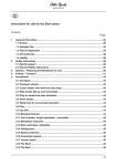
Voyager Evo Service Manual Table of contents Table of contents 1 1.1 1.2 1.3 Introduction .........................................................................................................................................................4 Foreword .............................................................................................................................................4 Support ...............................................................................................................................................4 Product Overview .................................................................................................................................4 2 2.1 2.2 Safety ....................................................................................................................................................................6 Explanation of Warning Symbols .............................................................................................................6 General Safety Instructions ....................................................................................................................6 3 3.1 3.2 3.3 3.4 3.4.1 3.4.2 3.4.2.1 3.4.2.2 3.4.3 3.4.4 3.4.4.1 3.4.4.2 3.5 3.5.1 3.5.2 3.5.3 3.5.4 3.5.5 3.5.5.1 3.5.5.2 3.6 3.6.1 3.6.2 3.6.3 3.6.4 3.6.5 3.6.6 3.7 3.7.1 3.7.1.1 3.7.1.2 3.7.1.3 3.7.1.4 3.7.2 3.7.2.1 3.7.2.2 3.7.2.3 3.7.2.4 3.8 3.8.1 3.8.2 3.8.3 3.8.4 3.8.4.1 Service Work .......................................................................................................................................................6 General Information ..............................................................................................................................6 Maintenance Schedule ..........................................................................................................................6 Required Tools .....................................................................................................................................7 Assembly A: Frame ...............................................................................................................................7 Replacing the Frame .............................................................................................................................7 Retrofitting the Accessory Mount, Anti-Tipper and Tip-Assist ......................................................................8 Retrofitting the Accessory Mount and Anti-Tipper ......................................................................................8 Retrofitting the Tip-Assist .......................................................................................................................9 Replacing Other Frame Components ......................................................................................................9 Adjusting the Anti-Tipper and Tip-Assist...................................................................................................9 Adjusting the Anti-Tipper .......................................................................................................................9 Adjusting the Tip Assist........................................................................................................................10 Assembly B: Footrest ..........................................................................................................................10 Replacing the Tube Footrest.................................................................................................................10 Replacing the Angle-Adjustable/Depth-Adjustable Footrest ......................................................................11 Replacing the Footplate .......................................................................................................................11 Installing/Adjusting the Lateral Heel Block .............................................................................................12 Adjusting the Footrests/Tube Footrest/Footplates ...................................................................................12 Adjusting the Lower Leg Length ...........................................................................................................12 Adjusting the Support Angle .................................................................................................................13 Assembly C: Seat/Seating System ........................................................................................................13 Replacing the Seat Plate ......................................................................................................................13 Replacing the Adaptable Seat Upholstery ..............................................................................................13 Retrofitting the Adaptable Seat Upholstery .............................................................................................14 Adjusting the Seat Upholstery ...............................................................................................................14 Cleaning the Seat Upholstery ...............................................................................................................15 Cleaning Seat Cushions ......................................................................................................................15 Assembly Group D: Back .....................................................................................................................15 Replacing the Back .............................................................................................................................15 Replacing the Back Plate .....................................................................................................................15 Replacing the Back Plate Brackets ........................................................................................................16 Replacing the Back Attachment Clamp Block .........................................................................................16 Replacing the Back Upholstery .............................................................................................................16 Adjusting the Back ..............................................................................................................................17 Adjusting the Back Height ....................................................................................................................17 Adjusting the Back Angle .....................................................................................................................17 Adjusting the Backrest .........................................................................................................................18 Adjusting the Back Upholstery ..............................................................................................................18 Assembly E: Side Panels .....................................................................................................................19 Replacing the Side Panels ...................................................................................................................19 Replacing the Side Panel Supports .......................................................................................................20 Replacing the Clothing Protector Lip .....................................................................................................20 Adjusting the Side Panels ....................................................................................................................20 Adjusting the "Standard" and "Clothing Protector" Side Panels................................................................20 2 | Ottobock Voyager evo Table of contents 3.9 3.9.1 3.9.2 3.9.3 3.9.4 3.9.5 3.9.6 3.10 3.10.1 3.10.2 3.10.2.1 3.10.2.2 3.10.3 3.10.3.1 3.10.4 3.10.4.1 3.10.5 3.10.5.1 3.10.5.2 3.10.5.3 3.10.5.4 3.10.5.5 3.10.5.6 3.10.6 3.10.6.1 3.10.6.2 3.10.6.3 3.10.6.4 3.10.6.5 3.11 3.11.1 3.11.2 3.11.3 3.11.4 3.11.4.1 Assembly F: Caster Wheels .................................................................................................................21 Replacing the Caster Wheels ...............................................................................................................21 Replacing the Caster Fork ...................................................................................................................22 Replacing the Caster Wheel Journal ......................................................................................................22 Replacing the Caster Wheel Adapter .....................................................................................................22 Adjusting the Caster Wheel Journal Angle ..............................................................................................23 Changing the Installation Position of the Caster Wheels ..........................................................................24 Assembly G: Rear Wheels ...................................................................................................................24 Replacing the Rear Wheels ..................................................................................................................24 Replacing the Drive Axle ......................................................................................................................25 Replacing a Clamp Block of the Axle Retainer ........................................................................................25 Retrofitting a Clamp Block for the Accessory Mount ................................................................................26 Replacing the Height Blocks ................................................................................................................26 Replacing a Clamp Block for Height Blocks ...........................................................................................26 Replacing the Stabiliser .......................................................................................................................27 Replacing a Stabiliser Clamp Block ......................................................................................................27 Adjusting the Rear Wheels ...................................................................................................................28 Adjusting the Horizontal Position of the Rear Wheels ..............................................................................28 Adjusting the Rear Wheel Axle ..............................................................................................................28 Adjusting the Track Width (additional adjustment) ...................................................................................29 Adjusting the Rear Wheel Camber ........................................................................................................30 Adjusting the 0°/3°/6° Rear Wheel Camber ............................................................................................30 Adjusting the Track .............................................................................................................................31 Maintenance Work on the Rear Wheel ...................................................................................................31 Replacing the Push Rings/Adjusting the Installation Position "narrow/wide" ...............................................31 Replacing/Retrofitting a Spoke Protector ...............................................................................................32 Tensioning the Spokes/Adjusting the Out-of-Round.................................................................................32 Adjusting the Quick-Release Axle ..........................................................................................................32 Inner Tube/Rim Tape/Tyre Replacement ................................................................................................33 Assembly H: Wheel Lock/Brake ............................................................................................................34 Replacing the Scissor Wheel Lock/Knee Lever Wheel Lock .....................................................................34 Replacing the Wheel Lock Clamping .....................................................................................................34 Replacing the Brake Block ...................................................................................................................35 Adjusting the Brakes ...........................................................................................................................35 Adjusting the Wheel Lock ....................................................................................................................35 4 4.1 4.2 Appendices ........................................................................................................................................................36 Technical data ....................................................................................................................................36 Maintenance Schedule ........................................................................................................................38 Voyager evo Ottobock | 3 Introduction 1 Introduction 1.1 Foreword • • • • • • Regular maintenance is important – it improves safety and increases the lifespan of the product. All Mobility products should be inspected and serviced once a year. However, we recommend inspecting, readjusting, and if necessary servicing the product every 6 months if the product is used frequently, by growing children or by users with changing clinical conditions. Only use original spare parts for all service and maintenance work. The service and maintenance tasks described here should only be completed by trained, qualified personnel and not by the user of the device. This service and maintenance manual refers to the respective spare parts catalogues and the instructions for use of the described products. Please use these documents together. Use the maintenance schedule (checklist) as a template for making copies. Retain completed maintenance schedules and provide the customer with a copy. Voyager Evo Instructions for Use (qualified per Instructions for Use (user) sonnel) 647G963=* 647G964=* 1.2 Support Your national Ottobock team will be happy to answer any technical questions. The contact addresses and tele phone numbers can be found on the back inside cover of the service manual. 1.3 Product Overview 1 Voyager evo – version with fixed back plate/seat plate 4 | Ottobock Voyager evo Introduction Max. load capacity: 100 kg (effective seat width: 280 - 460 mm) The lightweight wheelchair is a modular rigid-frame wheelchair for active use in open frame design. The one-piece aluminium or carbon frame, combined with a single-panel footplate or a tube footrest, offers high stability with a low net weight. The frame design allows the centre of gravity, seat depth, lower leg length, back angle and back height as well as camber to be adjusted. Various frame angles as well as straight and inward or outward offset versions are avail able. 1 2 3 4 5 6 Seat with seat pad Side panel Back cushion Back (here: fixed back plate) Rear wheel with push ring Quick-release axle release button Voyager evo 7 8 9 10 11 Caster wheel Caster fork Footrest Frame Wheel lock (here: scissor wheel lock) Ottobock | 5 Safety 2 Safety 2.1 Explanation of Warning Symbols WARNING Warning regarding possible serious risks of accident or injury. CAUTION Warning regarding possible risks of accident or injury. NOTICE Warnings regarding possible technical damage. 2.2 General Safety Instructions CAUTION Failure to observe installation instructions Pinching, crushing due to installation errors ► Do not reach between force-actuated surfaces during installation work. CAUTION Use of unsuitable tools Pinching, crushing or damaging the product due to use of unsuitable tools ► When completing the tasks, only use tools that are suitable for the conditions at the place of work and for which safety and the protection of health are assured with proper use. ► Observe the specifications in the section "Required Tools". CAUTION Re-use of self-locking nuts Tipping over, falling of the user due to unintended loosening of the screw connections ► Always replace self-locking nuts with new self-locking nuts after disassembly. NOTICE Tipping or falling of the product Damage to product due to lack of attachment ► When you work on the product, secure it so that it cannot tip over or fall over. ► Use a clamping fixture to secure the product whenever you work on it at a workbench. 3 Service Work 3.1 General Information INFORMATION Read the service manual before starting work. Familiarise yourself with the functions of the product prior to inspection and use. In order to do so, you can request this service manual and other documentation from the manufacturer (see the overview of national Ottobock branches on the inside of the back cover) or download from our homepage www.ottobock.de or www.ottobock.com. INFORMATION Clean and disinfect the product before commencing service work. Observe all product care and product-specific inspection instructions in the instructions for use. INFORMATION Many screw connections utilise screws and nuts equipped with a thread lock. If you loosen screw connections, be sure to replace the respective nut or screw with one equipped with a new thread lock. If new screws or nuts with thread lock are not available, apply a medium-strength liquid thread locking compound (such as Loctite® 241 or Euro Lock A24.20) to the existing screws. 3.2 Maintenance Schedule Maintenance schedule as a template for copying: see Page . 6 | Ottobock Voyager evo Service Work 3.3 Required Tools The following tools are required in order to perform the service work: • Reversible ratchet handle wrench and sockets (size: 8 – 24) • Torque wrench (measurement range 5 - 50 Nm) • Wrench (size: 8 – 24), contained in the 481C08=ST010 Tool Set • Allen wrench (size: 2.5 – 6), size 3 – 6 contained in the 481C08=ST010 Tool Set • Screwdriver (blade width: 2.5/3.5/5 mm) • Phillips head screwdriver (size: 2) • Hammer (approx. 300 g); soft-faced hammer • Pliers: cutting pliers, combination pliers, snap ring pliers • Pin punch, ø 3/4/5/6 mm • Stanley knife with sickle hooked blade and standard blade • Tyre mounting levers and inner tube repair kit • Workbench and vice with plastic jaws and rubber insert • Measurement equipment: yardstick, spirit level, back square • Liquid thread lock, "medium" and "strong" 3.4 Assembly A: Frame 3.4.1 Replacing the Frame To replace the frame, all mounted parts and assemblies have to be removed from the frame in sequence. Reason Defective frame Insufficient seat depth Replacing the frame and seat plate Information for ordering parts Specify serial number of the frame tubes Replacing the seat plate: Specify the serial number of the seat plate and the seat depth. Replacing the seat plate and frame tubes: Specify the serial number of the seat plate and frame tubes. 1) Remove the footrest (see Page 10). 2) Remove the caster attachment device (see Page 22). 3) Remove the rear wheels (see Page 24). 4) Remove the back plate and back plate brackets from the frame (see Page 15). 5) Remove the side panels and side panel supports (see Page 19). 6) Remove the wheel locks (see Page 34). 7) Loosen the Allen head screws on both sides of the front clamp block (see Fig. 2). 8) Loosen the Allen head screws on both sides of the rear clamp block (see Fig. 3). 9) Replace the frame tubes. 10) Slide the longer side of the frame tubes into the clamp blocks. The tube end must not project beyond the rear clamp block (see Fig. 4). 11) Align the frame tubes at an angle of 90° (see Fig. 5). 12) Tighten the Allen head screws on both sides of the front clamp block to 15 Nm (see Fig. 2). 13) Tighten the Allen head screws on both sides of the rear clamp block to 15 Nm (see Fig. 3). 14) Reinstall all parts and assemblies on the frame in their original positions. INFORMATION: Always observe the respective torque specifications in the sections for the individual assemblies (page numbers are in brackets behind the instructions above). 15) Check the following settings and adjust if necessary: 16) Wheel lock: adjustment of the wheel lock (see Page 35). 17) Footrests: lower leg length setting (see Page 12). 18) Caster wheel assembly: caster wheel journal angle adjustment (see Page 23). Voyager evo Ottobock | 7 Service Work 2 3 4 5 3.4.2 Retrofitting the Accessory Mount, Anti-Tipper and Tip-Assist CAUTION Incorrect installation of the anti-tipper/missing anti-tipper Tipping over, falling of the user due to failure to observe the installation instructions and because of incorrect adjustment ► Depending upon the settings of the chassis, the centre of gravity, the back angle and the experience of the user, the use of an anti-tipper may be necessary. ► For a small wheelbase and a backrest that is tilted far back, an anti-tipper may need to be installed on both sides, depending upon the user's experience. ► Verify that the anti-tipper has been installed and adjusted properly. Find the appropriate position with the assistance of a helper. The manufacturer offers an accessory mount for this product. This enables the installation of the anti-tipper and the tip-assist. A special clamp block is needed to install the accessory mount (see Fig. 6). 3.4.2.1 Retrofitting the Accessory Mount and Anti-Tipper 1) Loosen the drive axle (see Page 25). 2) Remove the clamp block of the axle retainer (see Page 25). 3) Install the clamp block for the accessory mount (see Fig. 6, item 1). 4) Slide the accessory mount with the anti-tipper into the clamp block (see Fig. 6, item 2). 5) Tighten the Allen head screws of the accessory mount to 15 Nm (see Fig. 7). 6) Install the drive axle (see Page 25). 7) Tighten the Allen head screws of the clamp brackets on the drive axle to max. 7 Nm (see Fig. 61). 8) Reinstall the drive axle (see Page 25). 8 | Ottobock Voyager evo Service Work 6 7 3.4.2.2 Retrofitting the Tip-Assist Like the anti-tipper, the tip-assist is installed on the accessory mount in the installation position provided. 3.4.3 Replacing Other Frame Components The replacement of some frame components is described in other sections: • Replacing the Drive Axle (see Page 25) • Replacing the Height Blocks (see Page 26) • Replacing the Stabiliser (see Page 27) 3.4.4 Adjusting the Anti-Tipper and Tip-Assist 3.4.4.1 Adjusting the Anti-Tipper INFORMATION In order to adjust the anti-tipper correctly, it may be necessary to combine the steps to adjust the length and angle. The anti-tipper (see Fig. 8) has to be adjusted precisely upon retrofitting and after every change of the rear wheel position. max. 5 cm 8 Adjusting the Length of the Pivot Arm 1) Remove the Allen head screw on the pivot arm (see Fig. 9, item 1). 2) Adjust the length of the pivot arm. 3) Bolt down the pivot arm. The outer edge of the anti-tipper roller has to project beyond the largest diameter of the rear wheels (see Fig. 8). Adjusting the Angle of the Pivot Arm 1) Remove the Allen head screw between the anti-tipper tube and the angle adjuster (see Fig. 10, item 1). 2) Loosen the second Allen head screw on the angle adjuster (see Fig. 10, item 2). 3) Set the angle of the pivot arm. 4) Bolt down the pivot arm. The max. distance between the anti-tipper rollers and floor is 5 cm (see Fig. 8). Voyager evo Ottobock | 9 Service Work 9 10 3.4.4.2 Adjusting the Tip Assist 1) Press the spring on the tip-assist (not illustrated). 2) Insert the tip-assist into the accessory mount. 3) Allow the spring to lock in. 3.5 Assembly B: Footrest 3.5.1 Replacing the Tube Footrest INFORMATION ► When installing the footrest, the lower leg length and footrest angle also need to be adjusted (see Page 12). ► Document the insertion depth before replacing the footrest/footplate. 1) Loosen the Allen head screws (see Fig. 11). 2) Pull out and replace the tube footrest (see Fig. 12). 3) If applicable: Replace clamp sleeves: → Pull out the clamp sleeve (see Fig. 13). → Position the new clamp sleeve. The flat side has to face in the direction of the clamping screws. 4) Evenly slide the footrest in to the frame up to the recorded insertion depth. Use a soft-faced hammer if neces sary. 5) Tighten the Allen head screws to 7 Nm. 11 10 | Ottobock 12 Voyager evo Service Work 13 3.5.2 Replacing the Angle-Adjustable/Depth-Adjustable Footrest 1) 2) 3) 4) Loosen the Allen head screws on both sides (see Fig. 14). Replace the footrest. Adjust the footrest (see Page 12 et seq.). On both sides, tighten the Allen head screws to 8 Nm (see Fig. 14). 14 3.5.3 Replacing the Footplate 1) Loosen the Allen head screws on the footplate (see Fig. 15). 2) Remove and replace the footplate. 3) If applicable: Remove and replace the clamp bracket. In order to do so, bend open the clamp bracket as far as possible and pull it off the tube. Slide the new clamp bracket onto the tube. 4) Preinstall the footplate with the Allen head screws. 5) Rotate the footplate to the desired angle. 6) Tighten the Allen head screws to 10 Nm. 15 Voyager evo Ottobock | 11 Service Work 3.5.4 Installing/Adjusting the Lateral Heel Block The lateral heel block can be installed using the pre-drilled holes on the footplate. 1) Install the lateral heel block using the Allen head screws on the underside of the footplate (see Fig. 16, item 1). 2) Before tightening, slide the lateral heel block in the slot to the desired foot width (see Fig. 17). 3) Tighten the Allen head screws. 16 17 3.5.5 Adjusting the Footrests/Tube Footrest/Footplates 3.5.5.1 Adjusting the Lower Leg Length The required footrest height depends on the lower leg length of the user and the thickness of the seat cushion. "Angle-adjustable" Footrest, "Fixed" Footrest 1) Loosen the Allen head screws above the footrest (see Fig. 18, item 1). 2) Adjust the lower leg length (continuously adjustable). The footrest must be inserted at least 60 mm into the frame tube. 3) Tighten the Allen head screws to 8 Nm. "Angle-Adjustable/Depth-Adjustable" Footrest The adjustment of this footrest can be fine-tuned as follows: 1) Loosen 2 Allen head screws respectively on each side of the footrest assembly. However, do not completely unscrew the Allen head screws (see Fig. 19, item 1). 2) After loosening the Allen head screws, pry the clamp washer out of the bore hole in the cross-tie using a suit able tool (e.g. screwdriver). Do not remove the clamp washer entirely. 3) Push the footrest assembly up/down slightly around the pivot point (see Fig. 19, item 2). Ensure that the crossties are parallel before re-tightening the screws. INFORMATION: During the adjustment process, never loosen the screws (see Fig. 19, Fig. 1 and Fig. 3) at the same time. 4) Tighten the Allen head screws to 10 Nm. In doing so, ensure that the clamp washer is parallel (not tilted) in the cross-tie for optimum fixation. INFORMATION: After each adjustment of the lower leg length, readjust the footrest angle. 18 12 | Ottobock 19 Voyager evo Service Work 3.5.5.2 Adjusting the Support Angle The footrest setting should be chosen so that the ankle is in a relaxed, comfortable position. "Fixed" Footplate The angle of the footplate cannot be changed (not illustrated). "Angle-Adjustable" Footrest 1) Loosen the Allen head screws on the clamp bracket (see Fig. 20, item 1). 2) Rotate the footplate to the desired angle (see Fig. 20, item 2). 3) Tighten the Allen head screws to 10 Nm. "Angle-Adjustable/Depth-Adjustable" Footrest 1) Remove the protective caps from the screw connection (see Fig. 19, item 3). 2) Loosen the Allen head screws above the footplate (not illustrated). 3) Rotate the footplate to the desired angle (see Fig. 19, item 4). 4) Tighten the Allen head screws to 10 Nm. Reinstall the protective caps. 20 3.6 Assembly C: Seat/Seating System 3.6.1 Replacing the Seat Plate 1) Loosen the Allen head screws on both sides (see Fig. 21, item 1). 2) Replace the seat plate. 3) Tighten the Allen head screws to 8 Nm. 21 3.6.2 Replacing the Adaptable Seat Upholstery 1) 2) 3) 4) 5) Pull the seat pad off the hook-and-loop fastener (see Fig. 26). Remove the Allen head screws between the seat upholstery and frame (see Fig. 22, item 1). Remove the seat upholstery. If applicable: Remove the upholstery bars (see Fig. 23, item 1). Install the new seat upholstery. Voyager evo Ottobock | 13 Service Work 6) Tighten the Allen head screws to 5 Nm (see Fig. 22, item 1). 7) If applicable: Adapt the seat upholstery to the needs of the user (see Page 14). 22 23 3.6.3 Retrofitting the Adaptable Seat Upholstery Installation Instructions To retrofit the adaptable seat upholstery, special clamp blocks have to be installed. In order to maintain the stability of the frame geometry, the seat plate should only be removed after installing the clamp blocks for the adaptable seat upholstery, the stabiliser and the frame tubes. After removing the seat plate, the adaptable seat upholstery can be installed. Replacing the Clamp Blocks 1) Remove the clamp blocks on the stabiliser (see Page 27). 2) Replace the clamp blocks (see Fig. 24; see Fig. 25). 3) Secure the clamp blocks (see Page 27). 24 25 Installing the Adaptable Seat Upholstery 1) Install the frame tubes (see Page 7). 2) Remove the seat plate (see Page 13). 3) Install the adaptable seat upholstery instead of the seat plate (see previous section). 4) Adjust the sag of the seat upholstery (see following section). 3.6.4 Adjusting the Seat Upholstery INFORMATION You can slightly correct the centre of gravity by making small changes to the sag of the seat upholstery. Larger corrections to the centre of gravity must be made by making changes to the settings on the frame, the axle unit and the caster wheels. The adaptable seat upholstery can be adjusted in segments to the needs of the user. 1) Remove the seat cushion. 14 | Ottobock Voyager evo Service Work 2) 3) 4) 5) Pull the seat pad off the hook-and-loop fastener (see Fig. 26). Pull the flap of the backrest pad off the hook-and-loop fastener and let it hang down. Loosen the backrest straps and then fasten together with the desired tension (see Fig. 27). Secure the backrest pad to the seat upholstery with the hook-and-loop fastener. To do this, pull the part of the flap that can be fastened forwards and fasten to the seat upholstery (see Fig. 41). INFORMATION: The part of the flap that can be fastened prevents sliding or falling through the gaps between the straps and protects against draughts. 6) Secure the seat pad to the seat upholstery by means of the hook-and-loop fastener with edges aligned (see Fig. 26, item 1). 7) Secure the seat cushion with the hook-and-loop fastener. 26 27 3.6.5 Cleaning the Seat Upholstery 1) Remove the seat upholstery (see Page 13). 2) Clean the seat upholstery with regular mild household detergent. 3) Reinstall the seat upholstery. 3.6.6 Cleaning Seat Cushions Standard Seat Cushion ► Clean the seat cushion according to the attached care label. Seat Cushion with Foam Core 1) Open the zipper and remove the foam core (see Fig. 28). 2) Clean the cover and foam core according to the attached care label. 3) Reinsert the foam core with proper alignment. Close the zipper. 28 3.7 Assembly Group D: Back 3.7.1 Replacing the Back 3.7.1.1 Replacing the Back Plate 1) Remove the wheels. Voyager evo Ottobock | 15 Service Work 2) 3) 4) 5) On each side, loosen the three Allen head screws (see Fig. 29, item 1). Replace the back plate. On each side, tighten the three Allen head screws to 8 Nm (see Fig. 29, item 1). Install the wheels. 29 30 3.7.1.2 Replacing the Back Plate Brackets 1) Remove the back plate (see Page 15) 2) Loosen the Allen head screws on both sides (see Fig. 30, item 1). 3) Replace the back plate brackets on both sides. 4) On both sides, tighten the Allen head screws to max. 10 Nm (see Fig. 30, item 1). 3.7.1.3 Replacing the Back Attachment Clamp Block 1) Remove the back plate brackets (see Page ). 2) Loosen the Allen head screw on the seat plate (see Fig. 31, item 1). 3) Replace the clamp block. 4) Position the clamp block so it is flush with the tube end (see Fig. 32). 5) Tighten the Allen head screw on the seat plate to 8 Nm (see Fig. 31, item 1). 31 32 3.7.1.4 Replacing the Back Upholstery 1) Remove the seat cushion and fold the seat pad forward (see Page 18). 2) Remove the backrest pad (see Page 18). 3) Remove and replace the worn backrest bands (see Fig. 39). 4) Remove the worn belt loops from the fleece pads and replace them (see Fig. 33). 5) Fasten the backrest bands together with the desired tension using the hook-and-loop fasteners (see Fig. 39). 6) Replace the backrest pad, seat pad and seat cushion and attach with hook-and-loop fasteners (see Page 18). 16 | Ottobock Voyager evo Service Work 33 3.7.2 Adjusting the Back 3.7.2.1 Adjusting the Back Height Adjustment on a Back Assembly with Back Plate The back height is continuously adjustable vertically by up to 25 mm. 1) On both sides, loosen all Allen head screws on the back plate (see Fig. 34). 2) Slide the back plate to the desired height. INFORMATION: Please note that the back angle can be adjusted now as well (see Fig. 35). 3) On both sides, tighten the Allen head screws to 8 Nm (see Fig. 34). Make sure that the right and left sides are parallel. 34 Adjustment on a Back Assembly with Back Upholstery The back height cannot be changed afterwards. 3.7.2.2 Adjusting the Back Angle CAUTION Missing anti-tipper Tipping over, falling of the user due to missing safety devices ► If the back is tilted far to the rear and in the case of a short wheelbase, 2 anti-tippers (one on each side) must be mounted and in a functional position; in the case of a long wheelbase, at least one anti-tipper must be mounted and in a functional position. ► Check that the anti-tipper is securely attached. Adjustment on a Back Assembly with Back Plate The back angle is continuously adjustable by up to 15°. 1) On both sides, loosen all Allen head screws on the back plate (see Fig. 34). 2) Move the back plate to the desired angle (see Fig. 35). NOTE: Please note that the back height can now be adjusted as well (see Fig. 34). 3) On both sides, tighten the Allen head screws to 8 Nm (see Fig. 34). Voyager evo Ottobock | 17 Service Work 35 Adjustment on a Back Assembly with Back Upholstery The back angle cannot be changed afterwards. 3.7.2.3 Adjusting the Backrest INFORMATION Following adjustment, the position of the seat bottom and side panels must be checked and readjusted if neces sary (see the relevant section). The backrest is continuously adjustable horizontally on the seat tubes (depending on the length of the seat tubes). Adjusting the Back Assembly with Back Plate 1) Remove the side panels. 2) Loosen the Allen head screws on the back assembly on both sides (see Fig. 36, item 1). 3) Adjust the back assembly. Check the position by measuring it afterwards (see Fig. 37). 4) If necessary: Adjust the side panels so that moving the back assembly to the desired position is possible. 5) On both sides, tighten the Allen head screws to 10 Nm (see Fig. 36, item 1). 36 37 3.7.2.4 Adjusting the Back Upholstery INFORMATION A well-adjusted backrest provides lasting comfort for the wheelchair user and reduces the risk of secondary dam age and pressure zones. Do not create too much pressure. INFORMATION Ensure that the user's pelvis is positioned as far back in the wheelchair as possible, i.e. between the backrest tubes. The backrest cover can be adjusted in segments to the needs of the user. 1) Remove the seat cushion. 2) Fold the seat pad forwards away from the hook-and-loop fastener (not illustrated). 18 | Ottobock Voyager evo Service Work 3) Pull the back padding up and off the hook-and-loop fastener on the back upholstery and remove it (see Fig. 38). 4) Loosen the backrest straps and then fasten together with the desired tension (see Fig. 39). 5) Fit the back padding and secure it with the hook-and-loop fastener to the back and seat upholstery: → Place the kink in the back padding at the top. The "V" in the padding (see Fig. 40, item 1) shows exactly where the kink is. → Pull the back padding flap tightly downwards. → Pull the part of the flap that can be fastened forwards and fasten tightly to the seat upholstery (see Fig. 41, item 1). INFORMATION: The part of the flap that can be fastened prevents sliding or falling through the gaps between the straps and protects against draughts. 6) Fasten the seat pad and the seat cushion. 38 39 40 41 3.8 Assembly E: Side Panels 3.8.1 Replacing the Side Panels 1) Loosen the Allen head screws (see Fig. 42, item 1). 2) Replace the side panels. 3) Firmly tighten the Allen head screws (see Fig. 42, item 1). Voyager evo Ottobock | 19 Service Work 42 43 3.8.2 Replacing the Side Panel Supports Rear Side Panel Supports 1) Loosen the Allen head screws at the rear (see Fig. 42, item 2). 2) Secure the spring on the Allen head screw or reinstall if needed (see Fig. 43, item 1). 3) Replace the side panel supports at the rear. 4) Retighten the Allen head screws at the rear. Front Side Panel Supports 1) Loosen the Allen head screws at the front (see Fig. 42, item 3). 2) Replace the side panel supports at the front. 3) Retighten the Allen head screws at the front. 3.8.3 Replacing the Clothing Protector Lip 1) 2) 3) 4) 5) 6) 7) Remove the seat pad. Remove the rear wheels (see Page 24). Loosen the Allen head screws (see Fig. 44, item 1). Replace the clothing protector lip. Use care to firmly tighten the Allen head screws (see Fig. 44, item 1). Install the rear wheels (see Page 24). Install the seat pad. 44 3.8.4 Adjusting the Side Panels 3.8.4.1 Adjusting the "Standard" and "Clothing Protector" Side Panels After adjusting the rear wheel position or backrest, the position of the side panels needs to be checked and may have to be adapted. Adjusting the Side Panel Depth 1) Loosen the Allen head screws between the side panel and side panel bracket (see Fig. 45, item 1). 20 | Ottobock Voyager evo Service Work 2) Adjust the side panel as needed. The side panels should be as close against the backrest as possible (see Fig. 45, item 2). 3) Tighten the Allen head screws to 8 Nm (see Fig. 45, item 1). Adjusting the Clothing Protector Lip 1) Loosen the Allen head screws between the side panel and clothing protector lip (see Fig. 45, item 3). 2) Adjust the clothing protector lip as needed. INFORMATION: Choose the setting so that the lip of the clothing protector is close enough to or far enough away from the tyre to exclude the risk of crushing. 3) Tighten the Allen head screws to 5–7 Nm (see Fig. 45, item 3). Adjusting the Side Panel Bracket The firm fit of the side panel can be influenced by slightly adjusting the Allen head screws (see Fig. 46). 45 46 3.9 Assembly F: Caster Wheels 3.9.1 Replacing the Caster Wheels INFORMATION Observe the seat height table in the "Technical Data". 1) 2) 3) 4) 5) 6) 7) → → Loosen the screw connection on the threaded axle (see Fig. 47, item 1). Remove the threaded axle/spacers. Remove the caster wheel. Insert the threaded axle with the first spacer bushing offset in one of the 4 bore holes (see Fig. 47, item 2). Install the caster wheel (see Fig. 48). Slide on the second spacer bushing (not illustrated). Tighten the threaded axle to 8 Nm. Once changed, the left and right caster wheels must have the same vertical position in the caster fork. Once the anterior seat height has been adjusted, the rear wheel tracking (see Page 31) and the caster wheel journal angle (see Page 23) must be checked and adjusted if required. 47 Voyager evo 48 Ottobock | 21 Service Work 3.9.2 Replacing the Caster Fork 1) Loosen the Allen head screw (see Fig. 49). 2) Replace the caster fork (see Fig. 50). 3) Tighten the Allen head screw to 8 Nm. 49 50 3.9.3 Replacing the Caster Wheel Journal 1) If necessary: Heat the plug guide (see Fig. 58, right) with hot air (~ 80 °C) to soften the Loctite. 2) Loosen the clamping on the plug guide. In order to do so, remove the Allen head screw on the inside while it is hot (see Fig. 51). 3) Instead of the bearing sleeve, slide a suitable lever tube into the caster wheel journal (not illustrated). 4) Pry the caster wheel journal (see Fig. 58, item 2) secured with Loctite out of the taper fitting (see Fig. 58, item 3). 5) Remove and replace the caster wheel journal (see Fig. 52). 6) Apply "high strength" Loctite to the new caster wheel journal. INFORMATION: Note that only approx. 5–7 min. is available for the subsequent steps 7–9. 7) Insert the caster wheel journal and adjust it so the caster fork is perpendicular to the floor (see Page 23, steps 7–9). 8) Tighten the Allen head screw to 23 Nm. 51 52 3.9.4 Replacing the Caster Wheel Adapter 1) 2) 3) 4) Remove the tube footrest and clamp sleeves (see Page 10). Loosen the Allen head screws (see Fig. 53). Replace the caster wheel adapter (see Fig. 54). Tighten the Allen head screw to 15 Nm. 22 | Ottobock Voyager evo Service Work 53 54 3.9.5 Adjusting the Caster Wheel Journal Angle When the rear wheels have been adjusted for the user, the caster wheel journal angle must be adjusted if needed. The caster wheel axles/caster wheels must be perpendicular to the ground to ensure optimum wheelchair driving characteristics (see Fig. 55). 1) If necessary: Heat the plug guide (see Fig. 58, right) with hot air (~ 80 °C) to soften the Loctite. 2) Loosen the clamping on the plug guide. In order to do so, remove the M8 Allen head screw on the inside while it is hot (see Fig. 56, item 1). 3) Loosen the bearing sleeve: → Loosen the set screw on the outside (see Fig. 56, item 2; see Fig. 57). → Remove the bearing sleeve (not illustrated). 4) Instead of the bearing sleeve, slide a suitable lever tube into the caster wheel journal (see Fig. 58, item 1). 5) Pry the caster wheel journal (see Fig. 58, item 2) secured with Loctite out of the taper fitting (see Fig. 58, item 3). 6) Remove the remaining Loctite from the surfaces and threads of the disassembled components (not illustrated). Apply new "high strength" Loctite. INFORMATION: Note that only approx. 5–7 min. is available for the subsequent steps 7–9. 7) Temporarily attach the bearing sleeve with caster fork in the caster wheel journal. 8) Set the caster wheel axle vertically. Check the 90° setting with a square (see Fig. 55). → The caster wheel axles/caster wheels on both caster wheel adapters must be positioned vertically. 9) Reinstall the caster wheel assembly. When tightening the screws, note the following torque values: → Allen head screw on the inside (see Fig. 56, item 1): 23 Nm → Set screw (secured with "medium" Loctite) on the outside to secure the bearing sleeve (see Fig. 56, item 2): 8 Nm 55 Voyager evo 56 Ottobock | 23 Service Work 57 58 3.9.6 Changing the Installation Position of the Caster Wheels INFORMATION Observe the seat height table in the "Technical Data". The front seat height can be adjusted by moving the caster wheels in the fork and by selecting the caster wheel size. 1) Unscrew the screw connection of the threaded axle (see Fig. 60). 2) Remove the threaded axle/spacers. 3) Remove the caster wheel. 4) Insert the threaded axle with the first spacer bushing offset in one of the bore holes. 5) Install the caster wheel. 6) Slide on the second spacer bushing (not illustrated). 7) Tighten the threaded axle to 8 Nm. → Once changed, the left and right caster wheels must have the same vertical position in the caster fork. → Once the anterior seat height has been adjusted, the rear wheel tracking (see Page 31) and the caster wheel journal angle (see Page 23) must be checked and adjusted if required. 59 60 3.10 Assembly G: Rear Wheels 3.10.1 Replacing the Rear Wheels 1) 2) 3) 4) Press in the button on the quick-release axle. Remove the rear wheel and replace it. Attach the rear wheel to the quick-release axle housing and release the button on the quick-release axle. The quick-release lock engages. The quick-release axle must not be removable after releasing the pushbutton. 24 | Ottobock Voyager evo Service Work 3.10.2 Replacing the Drive Axle INFORMATION To replace the drive axle with a larger or smaller rear wheel axle, the seat plate, back plate, stabiliser and tube footrest also have to be replaced. 1) 2) 3) 4) 5) 6) 7) Loosen the Allen head screws of the clamp brackets on both sides (see Fig. 61). Remove the clamp brackets (see Fig. 62). Loosen the Allen head screws of the clamp blocks on both sides (see Fig. 63). Replace the drive axle (see Fig. 64). Tighten the Allen head screws of the clamp blocks on both sides to 15 Nm (see Fig. 63). Mount the clamp brackets (see Fig. 62). Tighten the Allen head screws of the clamp brackets on both sides to max. 7 Nm (see Fig. 61). 61 62 63 64 3.10.2.1 Replacing a Clamp Block of the Axle Retainer 1) Loosen the Allen head screw of the clamp bracket (see Fig. 65). 2) Replace the clamp block (see Fig. 66). 3) Tighten the Allen head screw of the clamp bracket to max. 7 Nm (see Fig. 65). Voyager evo Ottobock | 25 Service Work 65 66 3.10.2.2 Retrofitting a Clamp Block for the Accessory Mount Instead of an axle retainer clamp block, a clamp block for mounting an accessory mount can be installed (see Page 8). 3.10.3 Replacing the Height Blocks 1) Remove the axle retainer clamp block (see Page 25). 2) Loosen the Allen head screw of the clamp bracket (see Fig. 67). 3) Replace the height block (see Fig. 68). INFORMATION: The height blocks always have to be replaced in pairs. 4) If applicable: Align the clamp bracket so that the curvature faces the direction of travel. 5) Tighten the Allen head screw of the clamp bracket to max. 7 Nm (see Fig. 67). 67 68 3.10.3.1 Replacing a Clamp Block for Height Blocks 1) Remove the rear wheel axle, clamp block of the axle retainer and height block (see previous section). 2) Remove the back attachment clamp block (see Page 16). 3) Loosen the Allen head screws on the seat plate (see Fig. 69, item 1). 4) Loosen the Allen head screw on the clamp block (see Fig. 69, item 2). 5) Replace the clamp block. Tighten the Allen head screws: → Allen head screw on the clamp block: 15 Nm → Allen head screw on the seat plate: 8 Nm 6) Reinstall the components that were removed. 26 | Ottobock Voyager evo Service Work 69 3.10.4 Replacing the Stabiliser INFORMATION To replace the stabiliser with a larger or smaller stabiliser, the seat plate, back plate, drive axle and tube footrest also have to be replaced. 1) 2) 3) 4) 5) 6) 7) Remove the frame tubes (see Page 7). Loosen the Allen head screws on the seat plate on both sides (see Fig. 70). Remove the clamp blocks (see Fig. 71). Replace the stabiliser. Install the clamp blocks on both sides. On both sides, tighten the Allen head screws on the seat plate to 8 Nm (see Fig. 70). Mount the frame tubes (see Page 7). 70 71 3.10.4.1 Replacing a Stabiliser Clamp Block INFORMATION When using adaptable seat upholstery, note that a special clamp block must be installed (see Page ). The install ation corresponds to the description that follows. 1) 2) 3) 4) 5) 6) Remove the frame tubes (see Page 7). Loosen the Allen head screws on the seat plate on the desired side (see Fig. 70). Remove and replace the clamp block (see Fig. 71). Reattach the clamp block. On both sides, tighten the Allen head screws on the seat plate to 8 Nm (see Fig. 70). Mount the frame tubes (see Page 7). Voyager evo Ottobock | 27 Service Work 3.10.5 Adjusting the Rear Wheels CAUTION Lack of fine adjustment of the rear wheels Tipping over, falling of the user due to incorrect adjustment ► Check the standard adjustments of the wheelchair for stability against tipping and function of the rear wheels. Avoid any extreme settings. CAUTION Incorrectly adjusted wheelbase Tipping over, falling of the user due to unstable settings ► Please note that with the rear wheel in the front position and with an unfavourable body position, the user may tip backwards even on level ground. ► Use an anti-tipper for inexperienced users and with extreme settings of the rear wheel. ► Be sure to position the rear wheels towards the rear for transfemoral amputees. This improves the stability of the wheelchair. CAUTION Incorrect mounting of the camber module Tipping over, falling of the user due to lack of adhesion ► Do not pull the camber module out too far. During installation the whole camber module must be fully enclosed by the clamping fixture. INFORMATION Changing the rear wheel position can also change the angle between the caster wheel journal and the ground. However, this must be approx. 90°. The knee lever wheel lock also has to be readjusted. 3.10.5.1 Adjusting the Horizontal Position of the Rear Wheels The horizontal rear wheel position can be changed by sliding the axle assembly horizontally on the seat tubes. Changing the rear wheel position has the following effects: Position of rear wheel Move to rear Effects • • • • • Larger wheelbase Larger turning circle Greater stability of the wheelchair Wheelchair is harder to tip backwards when crossing obstacles Position recommended for inexperienced users Move forwards • • • • Smaller wheelbase Less load on caster wheels = greater manoeuvrability Less stability of the wheelchair Wheelchair is easier to tip backwards when crossing obstacles INFORMATION: An anti-tipper can be installed if necessary. Position recommended only for experienced users • 3.10.5.2 Adjusting the Rear Wheel Axle The axle assembly is continuously adjustable horizontally on the seat tubes. 1) Remove the wheels. 2) Pull the side panels out of the guides on the side panel mountings. 3) Loosen the connection between the seat plate or seat upholstery and the seat tube clamps: → With a seat plate: Loosen the Allen head screws between the seat plate and seat tube clamps (see Fig. 72, item 1). → With seat upholstery: Loosen all Allen head screws between the seat upholstery and seat tube clamps (see Fig. 73, item 1). Remove the seat upholstery. 4) Loosen the Allen head screws respectively between the seat tube clamps and seat tubes (see Fig. 72, item 2). 5) Move the axle assembly to the desired position (see Fig. 74). 28 | Ottobock Voyager evo Service Work 6) Ensure that the depth setting is the same. For fine-tuning, measure the distance respectively between the centre of the axle tube and the centre of the lower screw on the back bracket (see Fig. 75). 7) Tighten the Allen head screws between the seat tube clamps and seat tubes to 15 Nm (see Fig. 72, item 2). 8) Reconnect the seat plate or seat upholstery and the seat tube clamps: → With a seat plate: Tighten the Allen head screws between the seat plate and seat tube clamps to 8 Nm (see Fig. 72, item 1). → With seat upholstery: At the height of the adjusted seat tube clamps, punch the seat upholstery with a 6 mm hole punch and drill 6 mm holes in the upholstery tubes. Tighten the Allen head screws between the seat upholstery and seat tube clamps to 8 Nm (see Fig. 73, item 1). 9) Slide the side panels back into the side panel mountings. Adjust the side panels if necessary (see Page 20). INFORMATION Following adjustment, the track of the rear wheel, the caster journal angle and the knee lever wheel lock must be checked and, if necessary, readjusted (refer to the corresponding section). 72 73 74 75 3.10.5.3 Adjusting the Track Width (additional adjustment) The camber modules can slide in the axle for adjusting the track width horizontally (see Fig. 76, item 1) . In case of camber modules with a screwed-in fitting, the counter nut on the fitting also has to be loosened and the fitting adjusted to the desired length. Adjustment on camber module for quick-release axles Ø 12 mm 1) Remove the wheels. 2) Loosen the Allen head screw respectively on the seat clamp (see Fig. 77). 3) Loosen the Allen head screw respectively on the axle tube clamp (see Fig. 78). INFORMATION: The adjustment should be made on one side first and then on the other. INFORMATION: The track width must be adjusted symmetrically on both sides. Set the track width so that the slanted rear wheels run freely. 4) Insert the rear wheel's quick-release axle into the camber module to aid removal (see Fig. 79). 5) Move the camber module to the desired position outwards with the aid of the quick-release axle or inwards with the help of a soft-faced hammer. Voyager evo Ottobock | 29 Service Work → Do not pull the camber module out too far. During installation the whole camber module must be fully enclosed by the axle tube clamp. → Check the position by measuring it afterwards. To do this, measure the distance between the outer side of the camber module and the outer side of the axle tube clamp. 6) Lightly clamp the camber module in the axle tube clamp. 7) Adjust the track width in the same fashion on the other side. Make sure that both camber modules have been adjusted symmetrically. 8) Make the track adjustments (see Page 31). 9) Tighten the Allen head screw respectively on the axle tube clamps to 15 Nm (see Fig. 78). 10) Tighten the Allen head screw respectively on the seat clamps to 7 Nm (see Fig. 77). 76 77 78 79 3.10.5.4 Adjusting the Rear Wheel Camber The rear wheel camber is adjusted by exchanging of the camber modules. This has the following effects: Position of rear wheel Wheel camber 3°/6° 0° position Effects • • • Wheelchair becomes more manoeuvrable, turns faster and tips less easily to the side Overall width increases Increased rolling resistance • • Narrow track, excellent straight-line stability Low rolling resistance 3.10.5.5 Adjusting the 0°/3°/6° Rear Wheel Camber The modular system of the product offers camber modules for different sloped settings of the rear wheels (example: see Fig. 80). 1) Remove the wheels. 2) Remove the camber modules (see Page 29). INFORMATION: Make sure that the same camber module is installed on both sides. 3) Exchange and install the camber modules (see Page 29). → Set the track width so that the slanted rear wheels run freely. 30 | Ottobock Voyager evo Service Work 4) 5) 6) 7) 8) → During installation the whole camber module must be fully enclosed by the axle tube clamp. → Check the position by measuring it afterwards. Lightly clamp the camber module in the axle tube clamp. Adjust the track width in the same fashion on the other side. Make sure that both camber modules have been adjusted symmetrically. Adjust the track (see Page 31). Use an adjustment aid (e.g. back square) to do so. Tighten the Allen head screw respectively on the axle tube clamps to 15 Nm (see Fig. 78). Tighten the Allen head screw respectively on the seat clamps to 7 Nm (see Fig. 77). 80 3.10.5.6 Adjusting the Track INFORMATION The track must be adjusted after the following adjustments have been made: Adjusting the track width: see Page 29 Adjusting the rear wheel camber: see Page 30 The track setting must be checked and, if necessary, adjusted after the following adjustments have been made: → Adjusting the horizontal position of the rear wheel: see Page 28 ► → → ► INFORMATION ► When adjusting the rear wheel track, always check the symmetry of the track width setting. To do this, meas ure the distance between the outer side of the camber module and the outer side of the axle tube clamp. ► The caster wheel journal angle should be checked immediately after every adjustment to the track ( et seq.). 1) Loosen the seat clamps (see Fig. 77) and axle tube clamps (see Fig. 78) so that the camber modules are only lightly clamped in the rear wheel axle (see Page 29). 2) Place the wheelchair on an even surface. Avoid twisting the axle when doing this. 3) Pull the rear wheel out slightly in order to make room for the installation. 4) A 90° back square placed on a level surface is used as an adjustment aid. 5) Carefully turn the camber module until the spanner flat is flush with the blade of the back square. The spanner flat of the camber module is now vertical (see Fig. 76, item 2). 6) Tighten the Allen head screws respectively on the axle tube clamps to 15 Nm (see Fig. 78). 7) Tighten the Allen head screws respectively on the seat clamps to 7 Nm (see Fig. 77). 3.10.6 Maintenance Work on the Rear Wheel 3.10.6.1 Replacing the Push Rings/Adjusting the Installation Position "narrow/wide" 1) Completely remove the tyre. 2) Unscrew/remove the push ring screws from the rim (see Fig. 81). 3) Tightly bolt the push rings onto the rim in narrow or wide installation position. 4) Completely reinstall the tyre. Voyager evo Ottobock | 31 Service Work 81 82 3.10.6.2 Replacing/Retrofitting a Spoke Protector Spoke protectors can be mounted to rear wheels with hollow rims. The spoke protectors are mounted with snap fasteners (attachment nipples). 1) Remove the rear wheels. 2) If present: Press out the attachment nipples from the worn spoke protector from the inside, e.g. with the handle of a hammer (see Fig. 83). 3) Remove and replace the spoke protector. 4) Position the spoke protector on the rim so that it is centred and you can see a spoke beneath each of the six bore holes. 5) From the outside, press in the attachment nipples until you hear them lock in place on the spokes. INFORMA TION: INFORMATION: In some cases, assembly with screws is required (see Fig. 84). Please refer to the information given in the spare parts catalogue. 83 84 3.10.6.3 Tensioning the Spokes/Adjusting the Out-of-Round Tensioning the Spokes 1) Completely remove the tyre (see Fig. 82). 2) Check the spokes' tension by shaking/moving the spokes. 3) If necessary, carefully adjust the tension of the spokes with spoke tensioner. 4) Completely reinstall the tyre. Adjusting the Out-of-Round Adjusting the out-of-round by a maximum of 1 mm requires special instruments and technical knowledge. The adjustment should be performed in a bicycle specialist workshop. 3.10.6.4 Adjusting the Quick-Release Axle The quick-release axle (see Fig. 85) should be adjusted so that it engages properly and so that the wheel has no play on the axle. 1) Hold the tip of the quick-release axle with a wrench (size 11). 2) Adjust the play by turning the nut on the end of the quick-release axle (size 19; see Fig. 85, item 1) in or out. 32 | Ottobock Voyager evo Service Work 85 86 3.10.6.5 Inner Tube/Rim Tape/Tyre Replacement INFORMATION When driving outdoors, always carry a repair kit and tyre pump (when using pneumatic tyres) in case of emer gency. Suitable tyre pumps are listed on the order form and are supplied with the product. An alternative is tyre foam, which fills your tyre and then hardens (available from bicycle shops etc.). Removal and Preparing for Installation 1) Carefully remove the tyre from the rim using appropriate tools. INFORMATION: Take care not to damage the rim or the inner tube. 2) Unscrew the valve nut from the valve and remove the tube. 3) Repair the tube according to the directions in the repair kit or replace it with a new tube. 4) Before fitting the tyre again, inspect the rim bed and tyre inner wall for foreign objects. This could have caused the puncture. 5) Before installing the tube, check that the rim band is in proper condition. The rim band protects the tube from being damaged by the ends of the spokes. 87 88 Replacing the Rim Band (only when necessary) 1) If the rim band needs to be replaced, remove it from the rim. 2) Install the new rim band on the inside of the rim, making sure the valve opening is in the right position. 3) Glue the rim band in place if this is intended. Ensure that all spoke ends are covered. Installing the Tube and Tyre 1) Behind the valve, push one side of the tyre over the edge of the rim. 2) Slightly inflate the tube until it starts to assume its round shape. 3) Unscrew the valve nut from the tube and push the valve through the valve opening in the rim. 4) Insert the tube into the tyre. Voyager evo Ottobock | 33 Service Work 5) Mount the other side of the tyre on the rim, starting from the position across the valve. Ensure that the tube is not pinched between the tyre and rim during this process. 89 90 Inflating the Tube 1) Ensure that the valve is positioned perpendicularly for proper positioning of the tube and tyre in the region of the valve. 2) Firmly screw on the valve nut. 3) Inflate the tube so that the tyre can still be pressed in easily with your thumb. INFORMATION: If the circumferential lines on the two sides of the tyre are both at an even distance from the rim, the tyre is centred. If not, let some air out and realign the tyre. 4) Inflate the tube to the maximum pressure specified by the tyre manufacturer (see information printed on the casing). 5) Firmly screw the valve cap onto the valve. 3.11 Assembly H: Wheel Lock/Brake 3.11.1 Replacing the Scissor Wheel Lock/Knee Lever Wheel Lock 1) 2) 3) 4) 5) Evenly loosen the two Allen head screws on the clamp bracket (see Fig. 91). Open the clamp bracket. Replace the wheel lock (see Fig. 92). Close the clamp bracket. Adjust the wheel locks (see Page 35). INFORMATION: Use new Allen head screws on the clamp bracket or secure the existing Allen head screws with liquid thread locking compound. 6) Tighten the Allen head screws on the clamp bracket to 15 Nm. 91 92 3.11.2 Replacing the Wheel Lock Clamping 1) Loosen the Allen head screws on the clamp bracket. 2) Pull the knee lever wheel lock out of the wheel lock clamping. 3) Pull the wheel lock clamping off the frame and replace it (see Fig. 93). 34 | Ottobock Voyager evo Service Work 4) Slide the knee lever wheel lock into the wheel lock clamping. 5) Close the clamp bracket. 6) Adjust the wheel locks (see Page 35). INFORMATION: Use new Allen head screws on the clamp bracket or secure the existing Allen head screws with liquid thread locking compound. 7) Tighten the Allen head screws on the clamp bracket to 15 Nm. 93 94 3.11.3 Replacing the Brake Block 1) Unscrew the Allen head screw on the brake block (see Fig. 94). 2) Remove/replace the brake block. 3) Tighten the Allen head screw to 6 Nm. 3.11.4 Adjusting the Brakes 3.11.4.1 Adjusting the Wheel Lock CAUTION Insufficient braking of the knee lever wheel lock Accident, falling of the user due to incorrect adjustment and improperly inflated tyres ► Check the air pressure of the rear wheels and the correct setting of the knee lever wheel lock. The correct tyre pressure is printed on the tyre. For rear wheels, the minimum air pressure is 7 bar. ► Only use original rear wheels with a verified maximum radial out-of-round of 1 mm. Adjusting the Knee Lever Wheel Locks/Scissor Wheel Locks This adjustment must be made after the rear wheel has been repositioned or during fine adjustment. 1) Loosen the Allen head screws in the clamp brackets (see Fig. 95, item 1). 2) Adjust/move the support for the knee lever wheel lock/scissor wheel lock to any position in the clamp bracket (knee lever wheel lock example: see Fig. 95, item 2). If necessary: Slide and twist the clamp bracket on the seat tube. 3) When the wheel lock is disengaged, the gap between the tyre and wheel lock bolt must not exceed 5 mm (see Fig. 96). INFORMATION: For special requirements when adjusting the scissor wheel lock, see the section "Special Requirements for Adjustments to the Scissor Wheel Locks". 4) Tighten the Allen head screws to 15 Nm. → After adjustment, the left and right knee lever wheel locks must both have the same braking force. Voyager evo Ottobock | 35 Appendices 5 mm 95 96 Special Requirements for Adjustments (All Types of Wheel Locks) Depending on the adjustment, it may be necessary to rotate or replace the support for the wheel lock. This makes further wheel lock adjustments possible. Special Requirements for Adjustments to the Scissor Wheel Locks • Install the scissor wheel lock such that it can be guaranteed that the swivelling parts can move freely without colliding (see Fig. 97; see Fig. 98). • The scissor wheel lock should not hit the frame when it is open. • For information on using the scissor wheel lock, see the instructions for use (user), reference number 647G964. 97 98 4 Appendices 4.1 Technical data INFORMATION ► Many of the technical data below are given in mm. Please note that product settings – unless otherwise spe cified – cannot be adjusted in the mm range but only in increments of approx. 0.5 cm or 1 cm. ► Note that the values achieved during adjustment may deviate from the values specified below. The dimension al tolerance is ±10 mm and ±2°. General Information Voyager Evo Maximum load capacity [kg] 100 1) Weight [kg] approx. 8 (for seat width 400 mm; seat depth 400 mm; 4" full rub ber caster wheels, 22" hollow rim) 36 | Ottobock Voyager evo Appendices Transport weights [kg]1) (for seat width: 440 mm; 4" full rubber caster wheels) Seat width [mm] Seat depth [mm]2) Back height [mm] Max. total height [mm] (for rear seat height: 500 mm; back height 500 mm; push handle) Min. tyre pressure [bar]4) Max. permissible inclination [°]5) Voyager Evo Frame: 6.9 – 9.8 22" rear wheel: 1.1 280 – 460 360 – 520 200 – 500 1030 7 10 1) The specified weights vary according to the selected options and model. With wheelbase extension: rear axle position + 80 mm 3) In accordance with ISO 7176-5, 8.12 4) Varies according to tyre option; see the print on the tyre wall 5) The anti-tipper is mandatory for an inclination of more than 10°. 2) Additional Information Voyager Evo Mass of the heaviest component [kg] Overall length with footrests [mm] Overall width [mm] Seat bottom angle Effective seat depth [mm] Effective seat width [mm] Front seat height [mm] Rear seat height [mm] Backrest angle [°] Backrest height [mm] Distance footrest to seat [mm] Angle footrest to seat bottom [°] Push ring diameter [mm] Turning radius [mm]1) Horizontal axle position [mm] 1) Minimum Maximum --9.8 730 910 470 650 Depends on seat height front/rear 360 520 280 460 445 530 395 495 3.6 9.5 200 500 350 450 0 90 490 530 490 650 45 100 In accordance with ISO 7176-5 Voyager evo Ottobock | 37 Appendices 4.2 Maintenance Schedule Maintenance Schedule Item Area Type of wheelchair: Inspection (check list) Serial number: Function/setting (depending on equipment) Frame Anti-tipper Tip-assist Frame pad Lower leg length adjustment Angle adjustment Plastic plate Lateral heel blocks Calf strap Seat upholstery Seat cushion Back upholstery Back tubes Angle adjustment Push handles Height setting Swivel mechanism Removability Arm rest padded, swing-away Tray Tyres (wear) Tyre pressure Caster wheel journal angle/caster wheel axles Screw connections on the frame Swivelling of the caster forks Running behaviour of the wheels Tyres (wear) Running behaviour of the wheels Spokes/push rings Quick-release axles Wheel camber Rear wheel attachment device Tetra axle Wheelbase extension Spoke protectors Braking function Swing-away mechanism Wheel lock lever extension Inspected for dam age/deformation x x x x x x x x x x x x x x x x x x x x x x x Screw connections inspected x x x x x x x x x x x x x x x x x x x x x x x x x x x x x x x x x Tray Lap belt x x x x A Frame Frame accessories B Footrests Footrest accessor ies C Seat D Back/push handles E Side panels Side Panel Accessories F G Caster wheel Rear wheel Rear wheel accessories H Wheel locks/brakes Wheel accessories Accessories 38 | Ottobock lock Customer: x x x x x x x x x x x x x x x x Voyager evo Appendices Do the wheelchair settings match the user's require ments? Maintenance was carried out by: Voyager evo on: Ottobock | 39 40 | Ottobock Voyager evo Voyager evo Ottobock | 41 42 | Ottobock Voyager evo Kundenservice/Customer Service Europe Otto Bock HealthCare Deutschland GmbH Max-Näder-Str. 15 · 37115 Duderstadt · Germany T +49 5527 848-3433 · F +49 5527 848-1460 [email protected] · www.ottobock.de Otto Bock Healthcare Products GmbH Kaiserstraße 39 · 1070 Wien · Austria T +43 1 5269548 · F +43 1 5267985 [email protected] · www.ottobock.at Otto Bock Adria Sarajevo D.O.O. Omladinskih radnih brigada 5 71000 Sarajevo · Bosnia-Herzegovina T +387 33 766200 · F +387 33 766201 [email protected] · www.ottobockadria.com.ba Otto Bock Bulgaria Ltd. 41 Tzar Boris III‘ Blvd. · 1612 Sofia · Bulgaria T +359 2 80 57 980 · F +359 2 80 57 982 [email protected] · www.ottobock.bg Otto Bock Suisse AG Pilatusstrasse 2 · CH-6036 Dierikon T +41 41 455 61 71 · F +41 41 455 61 70 [email protected] · www.ottobock.ch Otto Bock ČR s.r.o. Protetická 460 · 33008 Zruč-Senec · Czech Republic T +420 377825044 · F +420 377825036 [email protected] · www.ottobock.cz Otto Bock Iberica S.A. C/Majada, 1 · 28760 Tres Cantos (Madrid) · Spain T +34 91 8063000 · F +34 91 8060415 [email protected] · www.ottobock.es Otto Bock France SNC 4 rue de la Réunion - CS 90011 91978 Courtaboeuf Cedex · France T +33 1 69188830 · F +33 1 69071802 [email protected] · www.ottobock.fr Otto Bock Healthcare plc 32, Parsonage Road · Englefield Green Egham, Surrey TW20 0LD · United Kingdom T +44 1784 744900 · F +44 1784 744901 [email protected] · www.ottobock.co.uk Otto Bock Hungária Kft. Tatai út 74. · 1135 Budapest · Hungary T +36 1 4511020 · F +36 1 4511021 [email protected] · www.ottobock.hu Otto Bock Adria d.o.o. Dr. Franje Tuđmana 14 ·10431 Sveta Nedelja · Croatia T +385 1 3361 544 · F +385 1 3365 986 [email protected] · www.ottobock.hr OOO Otto Bock Service p/o Pultikovo, Business Park „Greenwood“, Building 7, 69 km MKAD 143441 Moscow Region/Krasnogorskiy Rayon Russian Federation T +7 495 564 8360 · F +7 495 564 8363 [email protected] · www.ottobock.ru Otto Bock HealthCare Two Carlson Parkway North, Suite 100 Minneapolis, MN 55447 · USA T +1 763 553 9464 · F +1 763 519 6153 [email protected] www.ottobockus.com Otto Bock Scandinavia AB Koppargatan 3 · Box 623 · 60114 Norrköping · Sweden T +46 11 280600 · F +46 11 312005 [email protected] · www.ottobock.se Asia/Pacific Otto Bock Slovakia s.r.o. Röntgenova 26 · 851 01 Bratislava 5 · Slovak Republic T +421 2 32 78 20 70 · F +421 2 32 78 20 89 [email protected] · www.ottobock.sk Otto Bock Sava d.o.o. Industrijska bb · 34000 Kragujevac · Republika Srbija T +381 34 351 671 · F +381 34 351 671 [email protected] · www.ottobock.rs Otto Bock Ortopedi ve Rehabilitasyon Tekniği Ltd. Şti. Ali Dursun Bey Caddesi · Lati Lokum Sokak Meriç Sitesi B Block No: 6/1 34387 Mecidiyeköy-İstanbul · Turkey T +90 212 3565040 · F +90 212 3566688 [email protected] · www.ottobock.com.tr Africa Otto Bock Algérie E.U.R.L. 32, rue Ahcène Outaleb - Coopérative les Mimosas Mackle-Ben Aknoun · Alger · DZ Algérie T +213 21 913863 · F +213 21 913863 [email protected] · www.ottobock.fr Otto Bock Egypt S.A.E. 28 Soliman Abaza St. Mohandessein - Giza · Egypt T +202 330 24 390 · F +202 330 24 380 [email protected] · www.ottobock.com.eg Otto Bock South Africa (Pty) Ltd Building 3 Thornhill Office Park · 94 Bekker Road Midrand · Johannesburg · South Africa T +27 11 312 1255 [email protected] www.ottobock.co.za Americas Otto Bock Italia Srl Us Via Filippo Turati 5/7 · 40054 Budrio (BO) · Italy T +39 051 692-4711 · F +39 051 692-4720 [email protected] · www.ottobock.it Otto Bock Argentina S.A. Av. Belgrano 1477 · CP 1093 Ciudad Autônoma de Buenos Aires · Argentina T +54 11 5032-8201 / 5032-8202 [email protected] www.ottobock.com.ar Otto Bock Benelux B.V. Ekkersrijt 1412 · 5692 AK Son en Breugel · The Netherlands T +31 499 474585 · F +31 499 476250 [email protected] · www.ottobock.nl Otto Bock do Brasil Tecnica Ortopédica Ltda Alameda Maria Tereza 4036 - Bairro Dois Córregos 13278-181 · Valinhos-São Paulo · Brasil T +55 19 3729 3500 · F +55 19 3269 6061 [email protected] · www.ottobock.com.br Industria Ortopédica Otto Bock Unip. Lda. Av. Miguel Bombarda, 21 - 2º Esq. 1050-161 Lisboa · Portugal T +351 21 3535587 · F +351 21 3535590 [email protected] Otto Bock HealthCare Canada 5470 Harvester Road Burlington, Ontario, L7L 5N5, Canada T +1 289 288-4848 · F +1 289 288-4837 [email protected] · www.ottobock.ca Otto Bock Polska Sp. z o. o. Ulica Koralowa 3 · 61-029 Poznań · Poland T +48 61 6538250 · F +48 61 6538031 [email protected] · www.ottobock.pl Otto Bock HealthCare Andina Ltda. Calle 138 No 53-38 · Bogotá · Colombia T +57 1 8619988 · F +57 1 8619977 [email protected] · www.ottobock.com.co Otto Bock Romania srl Şos de Centura Chitila - Mogoşoia Nr. 3 077405 Chitila, Jud. Ilfov · Romania T +40 21 4363110 · F +40 21 4363023 [email protected] · www.ottobock.ro Otto Bock de Mexico S.A. de C.V. Prolongación Calle 18 No. 178-A Col. San Pedro de los Pinos C.P. 01180 México, D.F. · Mexico T +52 55 5575 0290 · F +52 55 5575 0234 [email protected] · www.ottobock.com.mx Otto Bock Australia Pty. Ltd. Suite 1.01, Century Corporate Centre 62 Norwest Boulevarde Baulkham Hills NSW 2153 · Australia T +61 2 8818 2800 · F +61 2 8814 4500 [email protected] · www.ottobock.com.au Beijing Otto Bock Orthopaedic Industries Co., Ltd. B12E, Universal Business Park 10 Jiuxianqiao Road, Chao Yang District Beijing, 100015, P.R. China T +8610 8598 6880 · F +8610 8598 0040 [email protected] www.ottobock.com.cn Otto Bock Asia Pacific Ltd. Suite 3218, 32/F., Sun Hung Kai Centre 30 Harbour Road, Wanchai, Hong Kong · China T +852 2598 9772 · F +852 2598 7886 [email protected] Otto Bock HealthCare India Behind FairLawn Housing Society St. Gregorios Lane, Sion Trombay Road Chembur, Mumbai, 400071 · India T +91 22 2520 1268 · F +91 22 2520 1267 [email protected] · www.ottobock.in Otto Bock Japan K. K. Yokogawa Building 8F, 4-4-44 Shibaura Minato-ku, Tokyo, 108-0023 · Japan T +81 3 3798-2111 · F +81 3 3798-2112 [email protected] · www.ottobock.co.jp Otto Bock Korea HealthCare Inc. 4F Agaworld Building · 1357-74, Seocho-dong Seocho-ku, 137-070 Seoul · Korea T +82 2 577-3831 · F +82 2 577-3828 [email protected] · www.ottobockkorea.com Otto Bock South East Asia Co., Ltd. 1741 Phaholyothin Road Kwaeng Chatuchark · Khet Chatuchark Bangkok 10900 · Thailand T +66 2 930 3030 · F +66 2 930 3311 [email protected] · www.ottobock.co.th Other countries Otto Bock HealthCare GmbH Max-Näder-Straße 15 · 37115 Duderstadt · Germany T +49 5527 848-1590 · F +49 5527 848-1676 [email protected] · www.ottobock.com Ihr Fachhändler | Your specialist dealer Printed by: Otto Bock Mobility Solutions GmbH Lindenstraße 13 · 07426 Königsee-Rottenbach/Germany T +49 (0) 69 9999 9393 · F +49 (0) 69 9999 9392 [email protected] · www.ottobock.com Ottobock has a certified Quality Management System in accordance with ISO 13485. Template-Version: 2013-10-15 © Ottobock · 647G965=EN-01-1401 Versandanschrift für Rücksendungen/Adress for Returns: Otto Bock Manufacturing Königsee GmbH Lindenstraße 13 · 07426 Königsee-Rottenbach/Germany