1
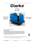
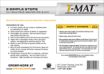
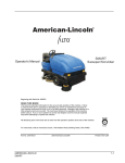
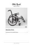
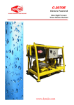
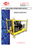
AMERICAN-LINCOLN
TECHNOLOGY
Operator's Manual
Instruction Book
ENCORE
R
ENCORE R
Beginning with Serial Number 180337
READ THIS BOOK
This book has important information for the use and safe operation of this machine. Failure
to read this book prior to operating or attempting any service or maintenance procedure to
your machine could result in injury to you or to other personnel; damage to the machine or to
other property could occur as well. You must have training in the operation of this machine
before using it. If you or your operator(s) cannot read English, have this manual explained
fully before attempting to operate this machine.
ISO 9001
UL
®
#
FILE A2287
All directions given in this book are as seen from the operator's position at the rear of the machine.
For new books, write to: American-Lincoln, 1100 Haskins Road, Bowling Green, Ohio 43402
Part No. 2-86-00315
AMERICAN-LINCOLN
ENCORE R
2003 American-Lincoln
®
56041768
Printed in the
USA
1-1
NOTE
1-2
AMERICAN-LINCOLN
ENCORE R
INDEX
Chapter 1
C
CONTROLS 21
D
DECIMAL-METRIC CONVERSION TABLE 5
DISCLAIMER 4
E
ELECTRICAL SCHEMATIC 53
H
HARDWARE ABBREVIATIONS 6
HYDRAULIC TORQUE REQUIRENMENTS 8
I
INDEX 3
M
MACHINE PREPARATION 17
MAINTENANCE 39
O
OPERATING INSTRUCTIONS 30
ORDERING PARTS 10
S
SAFETY PRECAUTIONS 11
SPECIFICATIONS 14
STANDARD HARDWARE & TORQUE VALUES 7
SYMBOLS 9
T
TROUBLESHOOTING 50
W
WIRE HARNESS CONNECTIONS 54
WIRE HARNESS CONNECTIONS-SPRAY WAND 58
WIRE HARNESS ROUTING & CONNECTIONS 56
AMERICAN-LINCOLN
ENCORE R
1-3
DISCLAIMER
DISCLAIMER
The information contained in this manual is believed correct at the time of publication.
American Lincoln assumes no responsibility or liability for unauthorized changes made to this
manual or pages removed, causing indirect or consequential damages resulting from the use
of the information appearing herein.
WARNING!
In the event that machinery or controls described herein are modified in any way, or in the
event that such machinery or controls are not maintained in a proper manner, the instructional
material contained herein may be rendered inaccurate. The information contained herein is to
be used only by persons knowledgeable in the operation of machinery such as that described
herein, or other persons being directly supervised by such knowledgeable persons.
No portion of this manual may be reproduced without the express written consent of:
AMERICAN LINCOLN
Product Engineering
1100 Haskins Road
Bowling Green, OH, 43402
(419) 352-7511 Fax: (419) 373-4284
Copyright 2003 American Lincoln. All rights reserved.
Printed in USA March 2003
1-4
AMERICAN-LINCOLN
ENCORE R
DECIMAL-METRIC CONVERSION TABLE
FRACTION
DECIMAL
MILLIMETER
FRACTION
DECIMAL
MILLIMETER
C-2001/9907
AMERICAN-LINCOLN
ENCORE R
1-5
HARDWARE ABBREVIATIONS
ABBREVIATIONS - SCREWS
ADJ
ADJ.SP
BHM
BHS
CAPT.SL
CAPT.WG
FHM
FIL.HM
HHC
HHM
HIHD
HSHC
HSFHC
KNH
MHHC
PHM
RHD
RHM
RHW
SHC
SHTB
SQ
TB
THM
WELD
WG
=
=
=
=
=
=
=
=
=
=
=
=
=
=
=
=
=
=
=
=
=
=
=
=
=
=
Adjusting Screw
Adjusting Plunger Screw
Binding Head Machine Screw
Button Head Socket Screw
Captivated Slotted Screw
Captivated Wing Screw
Flat Head Machine Screw
Filister Head Machine Screw
Hexagon Head Cap Screw
Hexagon Head Machine Screw
1/2 High Head Screw
Hexagonal Socket Head Cap Screw
Hexagonal Socket Flat Head Cap Screw
Knurled Head Screw
Metric Hexagon Head Cap Screw
Pan Head Machine Screw
Round Head Drive Screw
Round Head Machine Screw
Round Head Wood Screw
Shiny Crown Cap Screw
Shoulder Thumb Screw
Square Head Screw
Thumb Screw
Truss Head Machine Screw
Weld Stud
Wing Screw
ABBREVIATIONS - SETSCREWS
HS
S
SH
-KCP
-CP
-OP
-FDP
-HDP
-FP
-COP
=
=
=
=
=
=
=
=
=
=
Hexagonal Socket Setscrew
Slotted Setscrew
Square Head Setscrew
Knurled Cup Point Setscrew
Cup Point Setscrew
Oval Point Setscrew
Full Dog Point Setscrew
Half Dog Point Setscrew
Flat Point Setscrew
Cone Point Setscrew
C-2004
1-6
AMERICAN-LINCOLN
ENCORE R
STANDARD HARDWARE & TORQUE VALUES
SAE - Grade 8
SAE - Grade 5
Screw
Size
*6
*8
*10
*1/4
5/16
3/8
7/16
1/2
9/16
5/8
3/4
7/8
1
Grade
5
Plated
C
14
27
39
86
15
28
44
68
98
135
239
387
579
F
15
28
43
108
17
31
49
76
110
153
267
-
Grade
8
Plated
F
C
130
151
22
24
40
44
63
70
95
108
138
155
191
216
338
378
545
818
-
410H
Stainless
C
18
33
47
114
19
34
55
85
-
F
20
35
54
132
22
39
62
95
-
Type
F&T
& BT
Brass
5
9
13
32
6
10
16
-
C
20
37
49
120
-
F
23
41
64
156
-
Type
B, AB
21
34
49
120
-
C = Coarse Thread
F = Fine Thread
* = Torque values for #6 through 1/4 are lb./in. All others are lb./ft.
NOTE
Decrease the torque by 20% when using thread lubricant
The torque tolerance is ± on torque values.
C2000/9905
AMERICAN-LINCOLN
ENCORE R
1-7
HYDRAULIC TORQUE REQUIRENMENTS
HYDRAULIC TORQUE REQUIREMENTS
Refer to the following chart for torque values on all hydraulic hoses and fittings.
Nominal
SAE
Dash
Size
-3
-4
-5
-6
-8
-10
-12
-14
-16
-20
-24
O-Ring Face Seal End
Thread
Swivel
Size
Nut
Inch
Torque
LB-FT
*
*
9/16-18
10-12
*
*
11/16-16
18-20
13/16-16
32-35
1-14
46-50
1 3/16-12
65-70
1 3/16-12
65-70
1 7-16-12
92-100
1 11/16-12
125-140
2-12
150-165
SAE O-Ring Boss End
Thread
Str. Fitting
Size
or Locknut
Inch
Torque
LB-FT
3/8-24
8-10
7-16-20
14-16
1/2-20
18-20
9/16-18
24-25
3/4-16
50-60
7/8-14
72-80
1 1/16-12
125-135
1 3/16-12
160-180
1 5/16-12
200-220
1 5/8-12
210-280
1 7/8-12
270-360
* O-Ring face seal type end not defined for this tube size.
NOTE
Parts must be lightly oiled with hydraulic fluid.
C-2002
1-8
AMERICAN-LINCOLN
ENCORE R
SYMBOLS
THESE SYMBOLS IDENTIFY CONTROLS, DISPLAYS/FEATURES, AND SAFETY SYMBOLS ON THE MACHINE.
Battery Charger
Scrub Brush Down Heavy Pressure
Choke
Squeegee Down & Vacuum On
Fan On
Squeegee Up & Vacuum Off
Filter Shaker On
Squeegee Up & Vacuum On
Forward/Reverse
Solution Tank Low
Headlights
Solution Flow Control
Hopper Dump
Throttle
Hopper Return
Read Machine Manual
Before Operating or Servicing
Horn
No gas or combustibles in tank
Main Broom & Side Broom Up
Keep Away From Flames/
NO Smoking
Main Broom & Side Broom Down
Wear Eye Protection
No Step
Electrical Hazard
Off
Stay Clear
On
Moving Fan Blade
Power
Pinch Point/Crush Hazard
Recovery Tank High
Cover or Hopper Could Close/
Engage Support
Scrub Brush Down & On
Turn Key Off/Lock Wheel
Before Leaving Seat
Scrub Brush Up and Off
WARNING! / ATTENTION!
AMERICAN-LINCOLN
ENCORE R
1-9
ORDERING PARTS
INTERNET
http://www.alto-online.com
ALTO HEADQUARTERS
Incentive International A/S
Kongens Nytorv 28
P.O. Box 2064
1013 Copenhagen K
Tel.: +45 72 18 10 00
Fax: +45 72 18 11 64
E-mail: [email protected]
SUBSIDIARIES
CZECH REPUBLIC
ALTO Ceská Republika s.r.o.
Zateckych 9
14000 Praha 4
Tel.: +420 2 41 40 84 19
Fax: +420 2 41 40 84 39
E-mail: [email protected]
Web: www.wap-alto.cz
DENMARK
ALTO Danmark A/S
Industrikvarteret
9560 Hadsund
Tel.: +45 7218 21 00
Fax: +45 7218 21 05
E-mail: [email protected]
FRANCE
ALTO France S.A.
B.P. 44, 4 Place d’Ostwald
67036 Strasbourg Cedex 2
Tel.: +33 3 88 28 84 00
Fax: +33 3 88 30 05 00
E-mail: [email protected]
AUSTRALIA
ALTO Overseas Inc.
1B/8 Resolution Drive
P.O. Box 797
Caringbah, N.S.W.2229
Tel.: +61 2 95 24 61 22
Fax: +61 2 95 24 52 56
GERMANY
ALTO Deutschland GmbH
Guido-Oberdorfer-StraBe 2-8
89287 Bellenberg
Tel.: +49 0180 5 37 37 37
Fax: +49 0180 5 37 37 38
E-mail: [email protected]
AUSTRIA
ALTO Österreich GmbH
Metzgerstr. 68
5101 Bergheim/Salzburg
Tel.: +43 6624 5 64 00-14
Fax: +43 6624 5 64 00-55
E-mail: [email protected]
GREAT BRITAIN
ALTO Cleaning Systems
(UK) Ltd.
Bowerbank Way
Gilwilly Industrial Estate, Penrith
Cumbria CA11 9BN
Tel.: +44 1 7 68 86 89 95
Fax: +44 1 7 68 86 47 13
E-mail: [email protected]
BRAZIL
Wap do Brasil Ltda.
Rua 25 de Agosto, 608
83323-260 Pinhais/Paraná
Tel.: +55 4 12 10 67 40 0
Fax: +55 4 12 10 67 40 3
E-mail: [email protected]
CANADA
ALTO Canada
24 Constellation Road
Rexdale, Ontario M9W 1K1
Tel.: +1 416 6 75 58 30
Fax: +1 416 6 75 69 89
NETHERLANDS
ALTO Nederland B.V.
Postbus 65
3370 AB Hardinxveld-Giessendam
Tel.: +31 18 46 77 20 0
Fax: +31 18 46 77 20 1
E-mail: [email protected]
CROATIA
Wap ALTO Strojevi za ciscenje, d.o.o.
Siget 18a
10020 Zagreb
Tel.: +385 1 65 54 144
Fax: +385 1 65 54 112
E-mail: [email protected]
NORWAY
ALTO Norge A/S
Bjørnerudveien 24
1266 Oslo
Tel.: +47 22 75 17 70
Fax: +47 22 75 17 71
E-mail: [email protected]
SINGAPORE
ALTO DEN-SIN Singapore Pte Ltd.
No. 17 Link Road
Singapore 619034
Tel.: +65 62 68 10 06
Fax: +65 62 68 49 16
E-mail: [email protected]
Web: www.densin.com
SLOVENIA
Wap ALTO cistilni sistemi, d.o.o.
Letaliska 33
SLO-1110 Ljubljana
Tel.: +368 15 20 62 00
Fax: +368 15 20 62 10
E-mail: [email protected]
SLOWAKIA
Wap ALTO cistiace systémy s.r.o.
Remeselnicka 42
83106 Bratslavia-Raca
Tel.: +421 2 44 881 402
Fax: +421 2 44 881 395
E-mail: [email protected]
Web: www.wap-alto.sk
SPAIN
ALTO Iberica S.L.
Calle de la Majada No. 4
28760 Tres Cantos - Madrid
Tel.: +34 91 8 04 62 56
Fax: +34 91 8 04 64 63
E-mail: [email protected]
SWEDEN
ALTO Sverige AB
Aminogatan 18
431 04 Mölndal
Tel.: +46 3 17 06 73 00
Fax: +46 3 17 06 73 41
E-mail: [email protected]
USA
ALTO Cleaning Systems Inc.
12249 Nations Ford Road
Pineville, NC 28134
Tel.: +1 704 971 1240
Fax: +1 704 971 1241
E-mail: [email protected]
1. Use the model number, catalog number, and serial number when ordering.
2. Give the part number, description, and quantity of parts needed.
3. Give shipping instructions for either freight, UPS, or parcel post.
MACHINE CATALOG NUMBERS
505-945CE ENCORE R (34”) SCRUBBER
505-946CE ENCORE R (38”) SCRUBBER
1-10
AMERICAN-LINCOLN
ENCORE R
SAFETY PRECAUTIONS
The following safety labels are mounted on the machine
in the locations indicated. If the labels become damaged
or illegible replace with identical label.
Scrub deck presents hazard
for crushing, entanglement,
friction and abrasion
WARNING
ELECTRICAL HAZARD - Shocks can
cause serious personal injury
Disconnect battery before working
in this area
Repairs must be performed by
authorized personnel only
AMERICAN-LINCOLN
ENCORE R
1-11
SAFETY PRECAUTIONS
HAZARD SERIOUSNESS LEVEL
Signal words (DANGER, WARNING and CAUTION) are used to identify levels of hazard seriousness. The
degree of severity is based on the likely consequences of human interaction with the hazard.
DANGER
To warn of immediate hazards which will result in severe personal injury or death.
WARNING
To warn of hazard or unsafe practices which could result in severe personal injury.
CAUTION
To warn of hazards or unsafe practices which could result in minor personal injury.
ATTENTION
To warn of unsafe practices which could result in extensive equipment damage.
NOTE
To give important information or to warn of unsafe practices which could result in equipment damage.
For the safe operation of this machine, read and understand all WARNINGS, CAUTIONS AND NOTES.
PERSONAL SAFETY
•
•
•
•
•
•
•
•
•
Read this manual carefully. The following information signals potentially dangerous conditions to the
operator or equipment. Know when these conditions can exist then take necessary steps to train
machine operating personnel.
Dress appropriately; loose clothing, jewelry and other accessories may get caught in the machine and
cause physical injury.
Wear OSHA/NIOSH protective eye wear or prescription glasses to protect eyes.
Wear appropriate gloves when filling and/or draining tanks.
Before operating machine, test brake mechanism, lights and back up alarm (if applicable).
Observe maintenance schedule guidelines to assume optimal safe operation of the machine.
Be aware of pinch pints that exist on the machine.
Do not operate machine if you are tired, upset, ill on medication or intoxicated.
Be completely aware of your surroundings. STOP, LOOK, and LISTEN for other employees walking in or
around your cleaning area.
MACHINE SAFETY
•
•
•
•
•
•
•
•
•
•
•
1-12
Operator must be properly trained to operate machine.
Read this manual before operating machine
Familiarize yourself with all components and safety features.
Do not operate machine unless it is completely assembled.
Do not use machine other than intended use.
Report damages or maintenance problem immediately. Do not use machine until it has been repaired.
Repairs should be done by authorized personnel.
For storage, keep machine in a building.
This machine is not at tow truck and should not be used for towing.
Do not use this machine as a step or furniture.
Do not operate machine on public highways, gravel, sand, grass and other unsafe surfaces.
AMERICAN-LINCOLN
ENCORE R
SAFETY PRECAUTIONS
•
•
•
•
•
•
•
•
•
•
•
•
•
•
•
•
•
•
Be careful when operating the machine on a ramp or incline. Do not operate machine on incline greater
than 8° or longer than 100’. Always move slowly on a ramp. Do not turn this machine on a ramp.
Do not stop and leave this machine on a ramp. Always stop the machine on a level surface, put the
power switch in the on position.
To prevent injury, and damage to the machine, do not lift the machine or move it to an edge of a stair or
loading dock.
Turn off machine when unattended, filling, fueling or doing maintenance on machine (if applicable).
When carrying out maintenance, pull the key.
Do not operate machine near flammable materials, fire or explosion may occur.
Solution or recovery tank should not be filled with fuel or chemicals.
Read label on cleaning solutions to verify it is safe for machine.
Use a cleaning concentrate recommended by the chemical manufacturer.
Water solutions or cleaning materials used can leave wet areas on floor surfaces causing dangerous
conditions for the operator or other persons. Always put CAUTION signs near area you are cleaning.
Use care when reversing machine.
Always empty the solution tank and recovery tank before doing maintenance.
Unplug the battery first to prevent possible injury when servicing a machine.
Lead acid batteries generate gases, which can cause an explosion. Keep sparks and flames away
from batteries. NO SMOKING. Charge batteries only in area with good ventilation.
Always wear eye protection and protective clothing when working near batteries. Remove all jewelry.
Do not put tools or other metal objects across the battery terminals, or the tops of batteries.
Keep electrical parts of the machine dry.
Make sure that all labels, decals, warnings, cautions and instructions are fastened to the machine.
Get new labels and decals from American-Lincoln.
Do not use machine to pick up dusts hazardous to health.
Only use accessories according to this instruction manual. Use of other accessories may impair
safety.
WEEE Symbol Information
ENGLISH Correct Disposal of This Product (Waste Electrical & Electronic Equipment)
(Applicable in the European Union and other European countries with separate
collection systems)
This marking, shown on the product or its literature, indicates that it should not be
disposed with other household wastes at the end of its working life. To prevent possible
harm to the environment or human health from uncontrolled waste disposal, please
separate this from other types of wastes and recycle it responsibly to promote the
sustainable reuse of material resources. Household users should contact either the
retailer where they purchased this product, or their local government office, for details
of where and how they can take this item for environmentally safe recycling. Business
users should contact their supplier and check the terms and conditions of the purchase
contract. This product should not be mixed with other commercial wastes for disposal.
AMERICAN-LINCOLN
ENCORE R
1-13
SPECIFICATIONS
POWER SUPPLY
Encore R (34”)
Encore R (38”)
36 volt (6-6 volt batteries) 340 AH or 370 AH
36 volt (6-6 volt batteries) 340 AH or 370 AH
For machine to operate properly, voltage reading should fall within 32-40 vdc.
Guaranteed power sound level: LWA max = 96 dBA
(Operator) Sound pressure level: 77.2 dBA
CHARGER
Encore R (34” & 38”)
36 Volt output, 115V/60Hz or 230V/50Hz Input
MOTORS, VACUUM
1 HP (.74 kW), 3 stage, tangential discharge
MOTORS, BRUSH
1.7 hp (1.3kW)
MOTOR, DRIVE
1.5 hp (1.1kW)
WHEELS
(1) Front 12.0” (31.8 cm) (2) rear 12.0” (31.8 cm)
BRUSH SIZE
Encore R (34”)
Encore R (38”)
2-17” (43.2 cm) DIA.
2-19” (48.3 cm) DIA.
CLEANING PATH
Encore R (34 “)
Encore R (38”)
34” (86.4 cm)
38” (96.5 cm)
BRUSH SPEED
300 RPM
SOLUTION TANK
45 gallon (171 liter)
RECOVERY TANK
45 gallon (171 liter)
SPEED, TRANSPORT
8 km/h
SPEED, SCRUBBING
4 km/h
TURN RADIUS
56” (142.2 cm)
U-TURN AISLE WIDTH
80” (203.2 cm)
CLEANING RATE
Encore R (34”)
Encore R (38”)
37,000 sq. ft/hr (3426 sq. m/hr)
42,000 sq. ft/hr (3901 sq. m/hr)
GRADE CLEANING
3°
GRADE TRANSPORT
8°
LENGTH
71.5” (181.6 cm)
1-14
AMERICAN-LINCOLN
ENCORE R
SPECIFICATIONS
WIDTH
Encore R (34”) Machine
Brush Housings
Squeegee
33.5” (85 cm)
38.0” (96.5 cm)
42.0” (106.7cm)
Encore R (38”) Machine
Brush Housings
Squeegee
33.5” (85 cm)
41.0” (104.1 cm)
42.0” (106.7 cm)
HEIGHT
51” (129.5 cm)
HEIGHT W/OHG
80” (203.2 cm)
WEIGHT
Encore R (34”)
Encore R (38”)
1800 lb. (817.2 kg)
1820 lb. (826.3 kg)
VIBRATION LEVELS
Steering Wheel
Seat
<2, 5m/s2
<2, 5m/s2
WARRANTY
Our general conditions of business are applicable with regard to the guarantee. Subject to change as a
result of technical advances. The guarantee is invalidated if the machine is not operated in accordance with
these instructions or otherwise abused. The guarantee is invalidated if the machine is not serviced as
described.
MACHINE DATA
R
MACHINE NAME
DATE / SERIAL NUMBER
MODEL
RATED POWER
WEIGHT
IP X3
MAX OPERATING SLOPE
LWA
B
AMERICAN-LINCOLN
ENCORE R
1-15
SPECIFICATIONS
1-16
AMERICAN-LINCOLN
ENCORE R
MACHINE PREPARATION
Fig. 1
Your Encore R battery machine has been shipped complete, but do not attempt to operate without reading the
following instructions:
UNPACKING AND ASSEMBLING MACHINE
The Encore R is shipped on a pallet covered by a plastic bag and fastened with four hold down brackets.
1. Remove plastic bag.
2. Unbolt lag screws located on each corner of machine.
3) Lift out bracket located on each corner of machine from slot in machine frame.
4) Remove rear squeegee and hose from under rear squeegee location.
6) Position a 11° and 36” ramp on base of pallet.
11 DEGREE
36 INCHES
Fig. 2
AMERICAN-LINCOLN
ENCORE R
1-17
MACHINE PREPARATION
DISCONNECT TRACTION
HARNESS CABLE BEFORE
TOWING THE MACHINE
METAL BAR
BRAKE RELEASE LEVER
Fig. 3
ELECTRICALLY ACTUATED
MECHANICAL PARKING BRAKE
Fig. 4
WARNING
Disconnect the traction harness before towing the machine.
6) The machine is shipped with a metal bar between the electrically actuated parking brake and the brake
release lever to keep the electrically actuated parking brake disengaged.
7) Push machine down the ramp onto a flat surface.
WARNING
8) Remove the metal bar to engage the electrically actuated mechanical parking brake.
9) Connect rear squeegee hose and install squeegee blade as shown in manual.
10) Remove battery charger from under the seat in battery compartment (if applicable).
11) Install batteries.
-Turn the key to the “O” position
-Lift the hinged seat and cover, then disconnect seat switch and remove seat plate.
-Use a battery lifting device with a 150 LB. (68KG) capacity to place the batteries battery compartment.
-Install Battery wires as shown in manual.
-Plug the polarized connector from the battery on into the 36 Volt plug provided.
-Install scrub brushes as shown in the manual.
-Lower seat and cover assembly.
12) Charge batteries as shown in the manual. Read battery manufacturer literature for battery care and
maintenance.
WARNING
Do not charge batteries on a concrete grounded surface. Hydrogen gas is formed during the charging
operation and is explosive. Only charge batteries in a well ventilated area with the lid open. Avoid
any smoking, open flame, or electrical sparks.
1-18
AMERICAN-LINCOLN
ENCORE R
MACHINE PREPARATION
REMOVE BATTERY
FROM BOX
Fig. 6
Fig. 5
UNPACKING BATTERY
The batteries are shipped separately in six boxes as shown in figure 5. Open the boxes on a clean work
surface and lift out the battery as shown in figure 6.
SAFETY LATCH
6 VOLT
LEAD ACID
BATTERY
BATTERY
CONNECTOR
WIRE
BATTERY COMPARTMENT
BATTERY SPACER
(NARROW SIDE UP
BATTERY CONNECTOR
BATTERY SPACER
(NARROW SIDE UP)
SIDE PANEL
Fig. 7
Fig. 8
BATTERY INSTALLATION
To install batteries lift the seat cover and secure safety latch in notch. Pull up on the side panel and remove to
gain access to the battery compartment. Lower batteries using a 1000 lb. (454 KG) lifting mechanism to lift
and install batteries into battery compartment placing battery spacers to stop from moving. Connect battery
connector wires in series to batteries as shown in figure 8.
WARNING
Do not leave charged batteries on concrete surface, they will discarge.
AMERICAN-LINCOLN
ENCORE R
1-19
MACHINE PREPARATION
CONNECTOR
ASSEMBLY
(TO BATTERY)
Fig. 9
Connect the battery connector assembly to battery as shown in figure 9.
CONNECT BATTERIES
Fig. 10
LOWER SEAT TO
COVER BATTERIES
Fig. 11
Plug the battery connector assembly from the battery to the machine connector assembly as shown in figure
10. Reinstall the side panel and then release the safety latch and lower the seat as shown in figure 11.
1-20
AMERICAN-LINCOLN
ENCORE R
CONTROLS
8
1
9
3
2
5
4
10
7
6
12
13
11
Fig. 12
1.
2.
3.
4.
5.
6.
7.
8.
9.
10.
11.
12.
13.
Solution Flow Knob
Brush Switch
Low Solution Light (Left) High Recovery Light (Right)
Scrub Pressure Switch
Squeegee Vacuum Switch
ESP
Light Switch, Optional
LCD Display
Forward/Reverse Switch
Key Switch
Secondary Optional Brake Pedal (Bottom), Pedal Lock (Top)
Horn Button, Optional
Foot Throttle
AMERICAN-LINCOLN
ENCORE R
1-21
CONTROLS
CONSOLE
LCD DISPLAY
MENU BUTTON
Fig. 13
Fig. 14
LCD DISPLAY SCREEN CONTROL BUTTON
The Encore R is equipped with an LCD display allowing the operator to monitor machine operation. The LCD
display button is located in the center of the console to the right under the display. Pushing on the menu button
enables the operator to view screen functions and monitor machine status and operation. When the key switch
is turned on, screen 1 will automatically be displayed. Pressing the menu button will allow you to review
screens 2 and 3.
SCREEN 1
SCREEN 2
SCREEN 3
Fig. 15
1-22
AMERICAN-LINCOLN
ENCORE R
CONTROLS
BRUSH SWITCH
SCRUB
PRESSURE
SWITCH
Fig. 16
BATTERY STATUS
METER
SCRUBBING
DOWN
PRESSURE
SCRUB
BRUSHES ON
DECK SCRUBBING
PRESSURE METER
SOLUTION
FLOW ON
SOLUTION
FLOW
METER
Fig. 17
SCRUB BRUSH SWITCH
The scrub brush switch is located on the left side of the console to right of the solution control knob as shown
in figure 16. Pushing the scrub brush switch to up position will raise the scrub deck to the top position, the
scrub brushes will stop rotating, the water solenoid will de-energize and solution flow will stop. Pushing the
scrub brush switch down will lower the scrub deck to the set down pressure. The squeegee will lower and the
vacuum will activate. When the scrub brush and squeegee are on, they will be displayed as shown in figure 17.
The brushes will not rotate until the foot throttle is depressed. Releasing the foot throttle will raise the scrub
deck to the top position and the brushes will stop rotating.
SCRUB PRESSURE SWITCH
The scrub pressure switch is located on the left side of the console between scrub brush switch and the
squeegee/vacuum switch as shown in figure 16. Pushing the scrub pressure switch up selects the next
highest scrub setting available, increasing pressure. Selected pressure is displayed as a bar on the LCD
control panel. Pressing the scrub pressure switch down selects the next lowest setting available, decreasing
pressure as shown in figure 17.
AMERICAN-LINCOLN
ENCORE R
1-23
CONTROLS
SQUEEGEE
VACUUM
SWITCH
Fig. 18
SQUEEGEE VACUUM ON
Fig. 19
SQUEEGEE/VACCUM SWITCH
The squeegee vacuum switch is located on the left side of the console to the right of the scrub brush switch as
shown in figure 18. Pushing the squeegee/vacuum switch up raises and turns off the vacuum. Pushing the
squeegee/vacuum switch down lowers the squeegee and turns on the vacuum. When the vacuum is on, it is
displayed as shown in figure 19. Pressing down on the foot throttle with the forward/reverse switch in the reverse
position will raise the squeegee when it is down. The vacuum will turn off in 15 seconds after the squeegee is
raised.
1-24
AMERICAN-LINCOLN
ENCORE R
CONTROLS
SOLUTION FLOW
KNOB
LOW SOLUTION
LIGHT
HIGH RECOVERY
LIGHT
Fig. 20
SOLUTION FLOW ON
Fig. 21
SOLUTION FLOW CONTROL KNOB
The solution flow control knob is located on the console to the left of the scrub brush switch as shown in figure
20. When solution flow is on, the flow rate will be displayed as a bar shown in figure 21. The solution control
knob gives an output of 0-3 GPM. Turning the knob clockwise increased the amount of solution deposited.
Turning the knob counterclockwise decreases the amount of solution deposited. Solution flow will stop when
the brushes are off or the key is in the off position.
LOW SOLUTION INDICATOR LIGHT
The low solution amber indicator light is located on the left side above the switches on the console to the left of
the high recovery indicator light as shown in figure 20. When the low solution indicator light illuminates the
solution tanks need to be filled.
HIGH RECOVERY INDICATOR LIGHT
The high recovery red indicator light is located on the left side above the switches on the console to the right of
the low solution indicator light as shown in figure 21. When the high recovery indicator light illuminates the
recovery tank is full and needs to be drained and cleaned out.
AMERICAN-LINCOLN
ENCORE R
1-25
CONTROLS
FORWARD
REVERSE
SWITCH
KEY SWITCH
Fig. 22
Fig. 23
FORWARD/REVERSE SWITCH
The forward/reverse switch is located on the right side of the console to right side of the steering wheel as
shown in figure 22. Pushing the forward/reverse switch up will result in the machine moving forward when the
foot throttle is depressed. Pushing the forward/reverse lever switch down will result in the machine moving
backward when the foot throttle is depressed.
KEY SWITCH
The key switch turned to the right, the ”I” position, will activate all machine systems as shown in fugure 23.
HORN BUTTON
FOOT PEDAL
Fig. 24
FOOT THROTTLE
The foot throttle is located on the floor on the right side as shown in figure 24. Pressing the foot throttle
pedal down sets the machine in forward or reverse motion, the direction depending on the position of the
forward/reverse switch.
HORN BUTTON
The horn button is located on the floor of the operator’s compartment to the left of the optional parking brake
peda as shown in figure 24. Pressing the button with the left foot will activate the horn.
1-26
AMERICAN-LINCOLN
ENCORE R
CONTROLS
PEDAL LOCK
BRAKE PEDAL
Fig. 25
SECONDARY PARKING BRAKE (OPTION)
The machine is equipped with an electrically actuated mechanical parking brake on the front drive wheel that is
automatically engaged when the key is turned off or the drive wheel stops rotating. A secondary, mechanically
actuated parking brake is available as an option as shown in figure 25. To set the secondary parking brake,
press down the brake and then press the lock on the upper portion of the pedal. To unlock the parking brake,
push on the upper portion of the pedal lock to release it. The foot brake is not a method for slowing machine
travel or for stopping under normal conditions. This is accomplished by releasing the foot throttle.
AMERICAN-LINCOLN
ENCORE R
1-27
CONTROLS
LIGHT SWITCH
ESP
Fig. 26
ESP (OPTION)
The ESP switch is located on the left side of the console in between the squeegee/vacuum switch and the light
switch. The ESP switch transfers water from the recovery tank through a filter and into the solution tank. When
the switch is in the down position the pump will operate when the high recovery light is illuminated. Clean the
filter in the recovery tank when the tank is emptied.
NOTE
Do not place clean water in the recovery tank when using the ESP option, the solution tank could
become overfilled during operation.
LIGHT SWITCH (OPTION)
The light switch is located on the left side of the console to the left of the steering wheel as shown in figure 26.
Pushing the light switch to the up position will illuminate the optional light located in the center on the front of
the machine. Pushing the light switch to the down position will turn the light off.
HOUR METER
Fig. 27
HOUR METER
The hour meter is activated when the key switch is in the “on” position. Screen 2 on the LCD display shows
total hours and panel screen display 3 shows total hours, brush hours and traction hours. This is useful for
determining service intervals.
1-28
AMERICAN-LINCOLN
ENCORE R
CONTROLS
SEAT SWITCH
SEAT ADJUSTMENT LEVER
Fig. 28
SEAT ADJUSTMENT LEVER
This lever is located on front to the seat to the left allowing the seat to be moved forward and back as shown in
figure 28.
SEAT SWITCH
The seat switch is a interlock safety switch located on the underside the seat and is activated by the operator’s
body weight while seated. The machine will stop immediately if there is no operator present in the seat.
HAND LEVER
Fig. 29
PRE SWEEP (OPTION)
The sweeper is designed to turn the broom on as it is lowered. To lower the broom release hand lever on right
side.
AMERICAN-LINCOLN
ENCORE R
1-29
OPERATING INSTRUCTIONS
Note
Before starting, perform the pre-start checks.
PRE-START CHECKLIST
1. Check controls for proper operation.
2. Make sure all controls are in the off position
3. Be sure foot throttle is in the neutral position
4. Check all flaps for damage or wear
5. Check scrub brushes for wear
6. Fill solution tank with water and detergent
SOLUTION TANK
RECOVERY TANK
Fig. 30
TO FILL SOLUTION TANK
Remove the solution lid located on the back right side of the machine as shown in figure 30. Fill tank with 40
gallons of water and the correct mixture of American Lincoln Commercial cleaner for the job on hand, first
making sure that the solution control knob is “OFF.” Place the lid back on the solution tank.
TO START MACHINE
1. Release secondary parking brake (if equiped).
2. Turn key to “I” position.
TO TRANSPORT MACHINE
1. Make sure the brushes and squeegees are in the up or raised position with all other controls in the off
position.
2. Push the forward/reverse switch to desired position (up for forward and down for reverse)
3. Push down on the foot throttle to obtain desired travel speed, release foot throttle to stop.
WARNING
Do not turn the steering wheel sharply when the machine is in motion. The sweeper is very
responsive to movement of the steering wheel. Do not make sudden turns.
1-30
AMERICAN-LINCOLN
ENCORE R
OPERATING INSTRUCTIONS
DRAIN HOSE
BRUSHES
SQUEEGEE HOSE
SQUEEGEE
Fig. 31
TO BEGIN THE CLEANING OPERATION
1. Lower brushes to the desired position.
SCRUB DECK = NORMAL RANGE OR HEAVY
2. Place the squeegee switch in the lower position.
SQUEEGEE BLADE = LOWER
3. Move solution control knob to the desired setting and begin operation.
SCRUBBING THE AVERAGE FLOOR WITH LIGHT TO MEDIUM SOILAGE
In this operation, cleaning is accomplished in one pass, with simultaneous solution feed, scrubbing and dirty
water pick up. The rate of solution feed and the speed of travel required will vary with floor condition. This
knowledge will come with operator experience.
SAFETY FEATURES
SEAT SAFETY SWITCH - Machine will not move and parking brake will set if this switch is not activated.
SPEED INTERLOCK - Maximum machine speed will be reduced while scrub brushes are in use.
BRUSHES OFF IN NEUTRAL - Scrub brushes automatically disengage when machine is idle.
PARKING BRAKE INTERLOCK - Parking brake will automatically set when foot pedal is released.
AUTOMATIC RECOVERY VACUUM SHUT-OFF - Vacuum fans will shut down when recovery tank is full.
AMERICAN-LINCOLN
ENCORE R
1-31
OPERATING INSTRUCTIONS
SOLUTION
TANK
RECOVERY
TANK
STRAINER
SOLUTION
CONTROL
VALVE
SCRUB
BRUSH
SQUEEGEE
FLOOR CONTACT
Fig. 32
THE NON-RECYCLING OR STANDARD SCRUBBING MODE
During the scrubbing process, detergent solution water from the solution tank is fed to the solution line. There
it is fed to the floor where two disc scrubbing brushes work to dislodge soil. After scrubbing, the dirty solution
is vacuumed from the floor and discharged into the recovery tank.
Sensors in each tank will indicate, by lights on the control panel, when the water in the solution tank is too low
or when the water in the recovery tank is too high.
1-32
AMERICAN-LINCOLN
ENCORE R
OPERATING INSTRUCTIONS
SOLUTION
TANK
SOLUTION
PUMP
STRAINER
RECOVERY
TANK
STRAINER
SOLUTION
CONTROL
VALVE
SCRUB
BRUSH
SQUEEGEE
FLOOR CONTACT
Fig. 33
ESP OPERATING MODEESP OPERATING MODE
During the scrubbing process, filtered water from the solution tank is fed to the solution line and then to the
floor where two disc scrubbing brushes work to dislodge soil. After scrubbing, the dirty solution is vacuumed
from the floor and discharged into the recovery tank. At intervals, a float switch activates the recycling pump,
which sends filtered solution from the recovery tank to the solution tank.
AMERICAN-LINCOLN
ENCORE R
1-33
OPERATING INSTRUCTIONS
Fig. 34
SCRUBBING PATH
•
Scrub in straight paths. Do not bump posts. Do not scrape the sides of the machine.
•
When the machine is in motion, do not push the directional/speed control pedal all the way forward.
This is the same as starting in “high” and will put a strain on the motor and drive system.
•
Plan your sweeping and scrubbing in advance. Try to arrange long runs with minimum stopping and
starting. Sweep debris from narrow aisles out into main aisle ahead of time. Do an entire floor, or
section at on time.
•
Pick up oversize debris before sweeping.
•
Allow a few inches of overlap of sweep and scrub paths. This will eliminate leaving dirty patches.
•
Allow a few inches of overlap of sweep and scrub paths. This will eliminate leaving dirty patches.
•
Don’t turn steering wheel to sharply when machine is in motion. The machine is very responsive to
movement of the steering wheel; so avoid sudden turns.
•
Try to follow as straight a path as possible. Avoid bumping into posts or scraping the sides of the
machine.
•
When placing the machine in motion, avoid slamming the directional control pedal all the way
forward suddenly. This is equivalent to starting out in “HIGH” and puts needless strain on the drive
system. Periodically, turn the sweeping broom end for end to prevent the bristles from “settling” in
one direction.
TO STOP THE CLEANING OPERATION
Discontinue the cleaning operation when the low solution light or the high recovery light illuminates, this
indicates the solution tank is empty or recovery tank is full. Discontinue the scrubbing cycle, put all controls in
the forward position for transport and drive to the drain area.
NOTE
After stopping, perform these post operation checks.
1-34
AMERICAN-LINCOLN
ENCORE R
OPERATING INSTRUCTIONS
POST OPERATION CHECKLIST
Check Battery Condition and recharge, if necessary.
1. Check all flaps for wear, damage and adjustment.
2. Drain and clean recovery tank.
3. Clean recovery tank screen and float.
4. Check scrub brushes for wear or damage.
5. Check rear and side squeegee for wear, damage and adjustment.
DRAIN HOSE PLUG
DRAIN HOSE PLUG
DRAIN HOSE
DRAIN HOSE
Fig. 35
Fig. 36
DRAINING RECOVERY TANK
Fig. 37
TO DRAIN RECOVERY TANK
The drain hose for the recovery tank is located on the back of the machine. To drain the tank, remove and lower
the hose and place in a suitable floor drain as shown in figure 37. Open the drain hose plug as shown in figure
35 and 36.
IMPORTANT
Improper discharge of wastewater will damage the environment and is illegal. The U.S.
Environmental Protection Agency has established certain regulations regarding discharge of
wastewater. The local city and state regulations regarding wastewater discharge may be in effect
in your area. Understand and follow the regulations in your area. Be aware of the environmental
hazards associated with the substances you dispose of.
AMERICAN-LINCOLN
ENCORE R
1-35
OPERATING INSTRUCTIONS
RECOVERY TANK SCREEN
RECOVERY TANK HOSE
Fig. 39
Fig. 38
When the draining operation is completed, flush the recovery drain hose as shown in figure 38. Clean the
recovery tank and recovery tank screen as shown in figure 39. Close the drain hose plug, close recovery tank
lid and clip the drain hose into place.
DISK SCRUB BUSHES
SQUEEGEE PIN
BRUSH BRISTLES
SHOULD NOT
BE LESS THAN
3/4” HIGH
SIDE SQUEEGEE
DISK SCRUB BRUSH
Fig. 40
Fig. 41
Inspect the disc brushes and replace when bristles are reduced to 3/4 inch length as shown in figure 40 and
41. To order replacement brushes, see scrub brush options in this manual.
1-36
AMERICAN-LINCOLN
ENCORE R
OPERATING INSTRUCTIONS
REAR SQUEEGEE
SQUEEGEE BLADE
Fig. 43
Fig. 42
SIDE SQUEEGEE
Fig. 44
Inspect the rear and side squeegee blades for wear. If the wiping edge has become rounded, remove and
reinstall so the unworn edge is now the wiping edge. This process can be repeated until all four edges are
worn. If the squeegee blade has become rippled, it will need to be replaced. Inspect the inner flap on the rear
squeegee for wear and to ensure it has not been torn or damaged.
AMERICAN-LINCOLN
ENCORE R
1-37
OPERATING INSTRUCTIONS
Fig. 45
PRE SWEEP (OPTION)
The sweeper is designed to turn the broom on as it is lowered as shown in figure 45. To lower the broom
release hand lever on right side.
Fig. 46
FILTER BAG REPLACEMENT
The filter bag should be checked every time the pre sweep is used and replaced when full as shown in figure
46.
WARNING
There is a potential risk of the bag tearing and causing premature failure to the dust control motor
and the main and side broom motor.
1-38
AMERICAN-LINCOLN
ENCORE R
MAINTENANCE
5, 6
8
PINCH POINT
KEEP CLEAR
WARNING
PINCH POINT
KEEP CLEAR
WARNING
4
WARNING
WARNING
BATTERY BOX CAN SLIDE OFF
FORK LIFT.
MAY CAUSE SERIOUS PERSONAL
INJURY OR PROPERTY DAMAGE.
TIE SECURELY TO FORKS DURING
TRANSPORT. DRIVE AND STOP
WITH CAUTION.
BATTERY COVER COULD CLOSE UNEXPECTEDLY
AND CAUSE PERSONAL INJURY.
Engage Safety Latch Before Working in this area.
7
1, 3
2
Fig. 47
EVERY 8 HOURS or DAILY operation check and clean/adjust if necessary:
1. All flaps for wear or damage
2. Clean recovery tank
3. Scrub brushes for wear or damage
4. Rear squeegee for wear or damage
5. Charge and check batteries
50 HOUR MAINTENANCE CHECKLIST:
6. Check battery electrolyte level
7. Lubricate steering bearing and pivot
100 HOUR MAINTENANCE CHECKLIST:
8. Clean solution tank
For service assistance, consult your local American-Lincoln Distributor, For best performance, replace worn
parts with genuine American-Lincoln parts.
Refer all Maintenance and Service Requirements to Qualified Maintenance Personnel.
Do not attempt to service this machine until you have read and understood all Safety Warnings associated with
the equipment you are working on.
AMERICAN-LINCOLN
ENCORE R
1-39
MAINTENANCE
For safety, read and follow the service precautions below. Know the hazards associated with the equipment you
are working on to prevent personal injury or damage to equipment.
For service assistance, consult your nearest American-Lincoln dealer. For best performance replace worn parts
with genuine American-Lincoln parts.
Refer all maintenance and service requirements to qualified maintenance personnel.
DO NOT attempt to service this machine until you have read and understand all safety warnings associated
with the equipment you are working on.
•
WARNING
Maintenance and repairs must be done by authorized personnel only.
•
Electrical repairs must be done by authorized personnel only. Consult your American-Lincoln
Authorized Service Person to do service procedures. Use only genuine American-Lincoln
parts.
•
Always park on a level surface, turn key off, and engage parking brake before working on the
machine to keep it from creeping or rolling.
•
If towing or pushing is required, disconnect motor lead located on the terminal block on the
bottom of the machine.
•
Maintenance and repairs must be done by authorized personnel only. Always empty the
solution tank and the recovery tank before doing any maintenance. Keep all fasteners tight.
Keep adjustments according to the specifications as shown in the Service Manual for this
machine.
•
Always wear eye protection and protective clothing when working near batteries. Do not put
tools or other metal objects across the topes of the batteries. NO SMOKING.
•
To prevent damage to the machine, and discharge across the tops of the batteries, do not fill
the batteries above the bottom of the tube in each cell. Wipe any acid from the machine or
the tops of the batteries. Do not add acid to a battery after installation.
•
Always wear eye protection and protective clothing when working near batteries. NO
SMOKING.
•
Always empty the hopper and disconnect the batteries before doing any maintenance.
•
The hopper could fall and cause serious injury. Always engage the hopper safety arm before
working under the hopper.
•
To maintain the stability of this machine in normal operation, the overhead guard, or similar
equipment installed by the manufacturer as original equipment should not be removed. If it
becomes necessary to remove such equipment for repair or maintenance, this equipment
must be reinstalled before machine is placed back in operation.
1-40
AMERICAN-LINCOLN
ENCORE R
MAINTENANCE
LIFT SEAT TO ACCESS BATTERIES
-
+
-
+
+
+
+
-
+
-
-
+
- +
-
BATTERY
CHARGER
Fig. 48
Fig. 49
SAFETY LATCH
CONNECT BATTERIES
Fig. 50
Fig. 51
BATTERY CHARGING INSTRUCTION
When the batteries are disconnected (i.e. charging, replacement), the microprocessor needs to be reset by
turning the key switch on and raising the brush deck. When the red light comes on steady the batteries can
be charged.
1.
2.
3.
4.
5.
Lift seat cover, make sure safety latch is secure in notch.
Insert charging plug into battery receptacle.
Plug power cord into proper AC source.
Follow the charging instructions provided on the charger.
Maintain electrolyte level in batteries, check after charging. Add distilled water as needed.
AMERICAN-LINCOLN
ENCORE R
1-41
MAINTENANCE
•
WARNING
Do not remove the battery from the machine if there is waste in the solution tank.
•
Hydrogen gas is formed during the charging operation and is explosive! Only charge
batteries in a well-ventilated area with the lid open. Avoid any open flame or electrical
sparks. Pulling out the charger plug, with the charger still on, will cause an arc and must be
avoided.
•
Batteries are heavy. Get help to lift the batteries.
•
Always remove jewelry, wear protective clothing, and face protection when working near
batteries.
•
Lead acid batteries generate gases, which cause explosions. Keep sparks and flames away
from batteries charge the batteries only in area with good ventilation. NO SMOKING!
•
To prevent an explosion, disconnect the AC plug from the receptacle before connection or
disconnection the DC plug on the charger.
•
The battery box can slide off a forklift and cause severe personal injury or damage to
equipment. Ensure that the battery box is properly secured to the forks of the forklift during
transport, drive and stop with caution.
1-42
AMERICAN-LINCOLN
ENCORE R
MAINTENANCE
LIFT SEAT TO ACCESS BATTERIES
DISCONNECT BATTERIES
Fig. 52
Fig. 53
DISCONNECT
BATTERY CONNECTOR WIRE
SAFETY LATCH
BATTERY COMPARTMENT
BATTERY CONNECTOR
SIDE PANEL
Fig. 54
Fig. 55
BATTERY REMOVAL
When removing batteries
1. Lift the seat cover making sure the safety latch is secure in the notch.
2. Remove the side panel to gain access to battery compartment.
3. Unplug the battery connector assembly from the battery to the machine connector assembly.
4. Disconnect the battery connector wires from the batteries.
5. Remove battery spacers holding batteries in place.
6. Use a 100 lb. (454 KG) lifting mechanism to lift and remove batteries.
AMERICAN-LINCOLN
ENCORE R
1-43
MAINTENANCE
DISK SCRUB BUSHES
SQUEEGEE PIN
BRUSH BRISTLES
SHOULD NOT
BE LESS THAN
3/4” HIGH
SIDE SQUEEGEE
DISK SCRUB BRUSH
Fig. 56
Fig. 57
REPLACING THE SCRUB BRUSHES
Replace Scrub Brushes when the bristles become worn to 3/4" as shown in figure 56 and 57.
1.
2.
3.
4.
5.
6.
7.
Lower scrub brushes.
Swing open side squeegees
Lift scrub brushes
The scrub brush is held in place by a ring. Pull the brush straight down to remove it.
Push a new brush onto the scrub brush driver until it clicks in place.
Lower Scrub Deck to the NORMAL position and check the brush for proper floor contact.
Replace side squeegees.
REPLACING PADS ON A PAD DRIVER
Install a new pad when the old pad is worn or dirty. The pad driver assembly is removed and installed the same
way a standard scrub brush is. (See replacing the scrub brushes) To change pad follow this procedure.
1. The pad driver is held in place by a ring. Pull the pad driver straight down to remove it.
2. Remove the pad holder using the spring wire retainer.
3. Replace the worn pad.
1-44
AMERICAN-LINCOLN
ENCORE R
MAINTENANCE
ADJUSTMENT
CASTORS
Fig. 58
SQUEEGEE CASTER WHEEL ADJUSTMENT
Adjust if squeegee leaves water on floor. The wheels must be 3/16" (.476 cm) above the floor.
1. Set the parking brake.
2. Turn the key switch to the on position.
3. Put the Squeegee Blade Switch in the lower position.
4. Turn the key switch to the on position. This will turn off the vacuum fans.
5. Loosen the wheel brackets by turning the adjustment handles.
6. Adjust the wheels to 3/16" (.476 cm) above the floor.
7. Tighten the wheel brackets with the adjustment handles.
SQUEEGEE KNOB
Fig. 59
MAINTENANCE FOR THE REAR SQUEEGEE
To remove the squeegee, follow this procedure:
1.
2.
3.
4.
Remove the squeegee assembly by loosening the two knobs that attach the squeegee to the
machine as shown in figure 59. Pull the squeegee assembly off.
Inspect the squeegee blade.
If the blade is worn, turn the blade so that a new edge is in the wiping position.
Reinstall squeegee assembly on the machine.
Note
Toothed lock washers must be on top of support plate
AMERICAN-LINCOLN
ENCORE R
1-45
MAINTENANCE
SQUEEGEE CLAMP
Fig. 60
SQUEEGEE BLADE REPLACEMENT
Replace if front or rear blades are worn or damaged.
1. Set the parking brake.
2. Turn the key to the on position.
3. Put the Squeegee Blade Switch in the lower position.
4. Turn the key switch to the off position.
5. Remove the rear squeegee assembly.
6. Loosen the strap clamp.
7. Remove the old blades.
Push the new blades in until they are against the top of the squeegee. Retighten clamp
PLUG
Fig. 61
TO DRAIN SOLUTION TANK
Remove the cover from the solution tank, rotate the handle on the drain plug counterclockwise and then pull up
as shown in figure 61. After the tank has drained, flush out with clean water and reinstall the plug.
1-46
AMERICAN-LINCOLN
ENCORE R
MAINTENANCE
TO TIGHTEN BELT
PUSH DOWN
IDLER PULLEY
MAIL BROOM BELT
LOOSEN NUT
TO ADJUST BELT
Fig. 63
Fig. 62
PRE SWEEP (OPTION)
Main Broom Belt
1. Check belt tension adjustment as shown in figure 62.
2. Loosen idler pulley as shown in figure 63.
3. Move in slot in main frame.
4. Retighten.
LOOSEN NUT
TO ADJUST BELT
PULL FORWARD TO TIGHTEN BELT
SIDE BROOM BELT
Fig. 64
Side Broom Belt
1. Check belt tension adjustment as shown in figure 64.
2. Loosen pulley and broom nut.
3. Force pulley and broom forward.
4. Retighten.
AMERICAN-LINCOLN
ENCORE R
1-47
MAINTENANCE
INTERNAL HEX SCREW
FRONT COVER
Fig. 66
Fig. 65
2 AMP FUSES
70 AMP FUSE
FOR BATTERY
SHORT CIRCUIT
PROTECTION
10 AMP FUSES
Fig. 67
Fig. 68
FUSE REPLACEMENT
To replace fuses unscrew the four internal hex screws, and then remove the front cover as shown in figure 65
and 66. Check fuses with an amp meter to locate the blown fuse. Replace the fuse with one of exactly the
same size as shown in figure 67 and 68. Replace the cover and tighten the internal hex screws.
Fuse Part Nos.
2-00-05861 (2 amp)
2-00-05860 (10 amp)
8-28-05019 (70 amp)
1-48
AMERICAN-LINCOLN
ENCORE R
MAINTENANCE
FUSES
FU1 FU2 FU3 FU4 FU5 FU6 FU7 FU8
Fig. 69
Fuse 1
Fuse 2
Fuse 3
Fuse 4
Fuse 5
Fuse 6
Fuse 7
Fuse 8
10 Amp Scrub Deck Actuator Fuse
10 Amp Scrub Deck Actuator Fuse
10 Amp Squeegee Actuator Fuse
10 Amp Squeegee Actuator Fuse
2 Amp Water Flow Control Valve Fuse
2 Amp Tank Float Switch Fuse
10 Amp Light and Horn Fuse
10 Amp Option Pump Fuse
WARNING
Replace fuses with the same size fuse to avoid damage to electrical components.
AMERICAN-LINCOLN
ENCORE R
1-49
TROUBLESHOOTING
PROBLEM
Poor scrubbing.
Water splashes from sides
of scrub deck.
Poor sweeping (Option).
1-50
PROBABLE CAUSE
1. Worn scrub brushes.
2. Incorrect method of
operation.
3. Wrong cleaning agent
or mixture.
4. Poor solution
distribution.
5. Brushes won’t turn.
1. Scrub deck
bumpers, poor
contact with floor.
2. Squeegee blades
worn or damaged.
3. Too much solution.
1. Broom jammed.
2. Hopper full.
3. Broom does not turn
4. Hopper not installed
correctly.
5. Poor broom pattern.
6. Flaps worn.
REMEDY
1. Replace brushes
when scrub reaches
worn zone. Brushes
should be replaced
when bristles worn
to ¾”.
2. Check scrubbing
procedure, brush
pressure, type of
cleaning agent and
solution flow-all are
important to the
scrubbing process.
3. Use AmericanLincoln
recommended
cleaning materials.
4. Check solution
strainer and clean
feed hoses for
obstructions. Check
valve control for
proper operation.
5. Check wiring
connections.
1. Readjust blades for
proper contact.
2. Replace and adjust.
3. Shut off solution
flow 5’ to 10’ before
making turns.
1. Remove obstruction.
2. Empty.
3. Adjust or replace
broom belts. Reset
circuit breakers
adjust broom micro
switches. Repair
loose wire
connections.
4. Reinstall.
5. Adjust sweep
pattern.
6. Repair or replace.
AMERICAN-LINCOLN
ENCORE R
TROUBLE SHOOTING
Machine moves slow or
erratically.
Machine does not move.
AMERICAN-LINCOLN
ENCORE R
1. Battery charge low.
2. Brakes dragging.
3. Loose connection at
foot pedal.
4. Overload of drive
circuit.
1. Blown fuse.
2. Battery unplugged.
1.
2.
3.
4.
Change.
Adjust.
Repair.
Remove obstruction,
put drive pedal in
neutral.
5. Adjust.
1. Check fuse and
replace if necessary.
2. Plug in battery.
1-51
TROUBLE SHOOTING
PROBLEM
Machine moves slow or
erratically
PROBABLE CAUSE
1. Battery charge low
2. Brakes dragging
3. Loose connection at foot
pedal
4. Overload of drive circuit
1.Change
2. Adjust
3. Repair
1. Blown fuse
1. Check fuse and replace if
necessary
2. Pug in battery
Machine does not move
2. Battery unplugged
1. Recovery tank full
2. Squeegee is worn or
damaged
3. Clogged suction hose or
pick up tool
Poor water pick up at
squeegee
4. Loose connections
between suction hose and
squeegee
5. Vacuum motors not
running
6. Plugged filter
7.Vacuum float cage clogged
8. Vacuum float shut off
9. Air leaks in suction hose
and connection
10. Air leaks at recovery tank
cover and/or manifold hose
11. Drain hose or drain plug
leaking or not closed properly
Water spills from squeegee
Squeegee leaves wet spots
Squeegee makes excessive
noise
1-52
REMEDY
1. Side squeegee blades
have poor contact with floor
2. Squeegee blades worn or
damaged
3. Too much solution being
applied before making turns
4. Brushes rotating opposite
direction
4. Remove obstruction, put drive
pedal in neutral, adjust
1. Empty tank
2. Examine squeegee rubber blade
for cuts or worn spots/replace if
necessary
3. Disconnect suction hose from
squeegee; flush squeegee and
hose thoroughly
4. Check all hose connections for
looseness or damage
5. Reset circuit breaker or repair
loose connection
6. Clean filter element in vacuum
manifold
7. Clean perforated metal
thoroughly
8. Excessive foam build up;
change cleaning chemical mixture
(use A-L approved material)
9. Repair or replace hose and
connections
10. Repair or replace seal and
hose
11. Close, repair or replace drain
plug in recovery tank
1. Readjust blades for proper
contact
2. Replace and adjust blades
3. Shut off solution flow 5-10 feet
pior to
1. Lift actuator out of
adjustment
2. Squeegee wheels out of
adjustment
1. Blades worn or damaged
AMERICAN-LINCOLN
ENCORE R
NOTES
AMERICAN-LINCOLN
ENCORE R
1-55
Division of Nilfisk-Advance A/S
Industrivej 1
9560 Hadsund
Denmark
Tel.: (+45) 72 18 21 00
Fax: (+45) 72 18 21 11
E-mail: [email protected]
E-mail: [email protected]
www.nilfisk-alto.dk