1
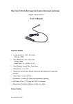
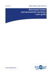
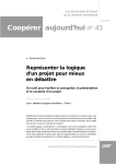
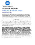
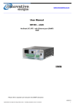
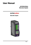
User Manual GSM enabled - SMS Protocol Converter DZC-PCON-smsProtoCon-IE1 IE Model Code: PROTOCON-GSM Revision: 1 Revision Date: Mar 2012 Innovative Energies Ltd . 1 Heremai Street, Henderson NZ . Tel: +64 9 835 0700 . [email protected] . www.innovative.co.nz TABLE OF CONTENTS TABLE OF CONTENTS .................................................................................................................. 2 INTRODUCTION.......................................................................................................................... 3 DEVICE SCHEMATIC AND IO CONNECTIONS................................................................................. 4 ELECTRICAL CONNECTIONS: ..................................................................................................................... 4 WIRING DIAGRAMS ................................................................................................................................ 5 FRONT PANEL INDICATIONS AND CONTROLS .............................................................................. 6 DIP SWITCHES SETTINGS & LOCAL PROGRAMMING OF THE DEVICE ............................................. 6 INSTALLING AND REMOVING THE SIM CARD ............................................................................... 9 SMS STRING FORMATS ............................................................................................................. 10 MONITORING OF POWER SUPPLY PARAMETERS ........................................................................................ 10 MONITORING OF POWER SUPPLY SETTINGS .............................................................................................. 10 MONITORING OF BATTERY CONDITION TESTING AND DIGITAL INFORMATION ................................................ 11 MONITORING OF ANALOGUE AND DIGITAL INFORMATION .......................................................................... 11 CONTROL OF ALL DIGITAL VALUES .......................................................................................................... 12 CONTROL OF BATTERY CONDITION TEST .................................................................................................. 13 ENABLE/DISABLE OF AUTOMATIC BATTERY CONDITION TEST ...................................................................... 13 CONTROL OF DIGITAL OUTPUTS ............................................................................................................. 14 ENABLING OF STARTUP MESSAGE ........................................................................................................... 14 DISABLING OF STARTUP MESSAGE .......................................................................................................... 15 SETTING OF TIME AND DATE .................................................................................................................. 15 AUTOMATIC MESSAGING CONTROL ........................................................................................................ 16 SETTING OF PHONE NUMBERS ............................................................................................................... 16 DEVICE CONFIGURATION .......................................................................................................... 17 SPECIFICATIONS ....................................................................................................................... 17 ELECTRICAL ......................................................................................................................................... 17 COMMUNICATIONS .............................................................................................................................. 17 HARDWARE ........................................................................................................................................ 17 LED INDICATIONS ................................................................................................................................ 17 REVISION HISTORY ................................................................................................................... 18 2 INTRODUCTION The DZC-PCON-SmsProtoCon-IE1 is a GSM-Enabled protocol converter and Input/Output Module for Innovative Energies Power Supplies with the following features: Communicates via the GSM (Global System for Mobile Communication) network. Communicated to the central uSCADA software and mobile phones via SMS (Short Message Service) Has 8 Volt Free Digital Inputs (Can be set to Normally Open or Normally Closed) Has 2 Relay Outputs (500mA @ 24VDC) Communicates with SR ... i DC UPS (back up charger) to provide the following information o Indications: Battery Bad Alarm Battery Missing Alarm Battery Low Alarm Power Supply Overload Alarm Communication Interface (this device) to Power Supply - Comms. Alarm Mains Failure Alarm Battery Condition Test Active Alarm o Controls: Battery Condition Testing Start/Stop Automatic Battery Condition Testing Enable/Disable Fully compatible with the DoZeener Controls uSCADA Software Setup of a maximum of 4 mobile phone recipients and the central uSCADA base station Automatic Time Synchronization with the central uSCADA Software Two Level PIN Protection – Monitoring Only and Monitoring and Control 8 Automatic Update Periods to the central uSCADA software Possibility to set time delays before sending digital input and power supply digitals activation alarms. Possibility to disable digital outputs remotely Can be remotely configured via the GSM network. 3 DEVICE SCHEMATIC AND IO CONNECTIONS ELECTRICAL CONNECTIONS: The diagram below shows the electrical connections as seen from above. 1. 2. 3. 4. 5. 6. 7. 8. 9. 10. 11. 12. 13. 14. 15. 16. 17. 18. 19. 20. 21. 22. 23. 24. 25. 26. 27. 28. 29. 30. 31. 32. 33. 34. 35. 36. 37. 38. 39. 40. Digital Input 1 + Digital Input 1 – Digital Input 2 + Digital Input 2 Digital Input 3 + Digital Input 3 Digital Input 4 + Digital Input 4 Digital Input 5 + Digital Input 5 Digital Input 6 + Digital Input 6 Digital Input 7 + Digital Input 7 Digital Input 8 + Digital Input 8 Power In + (9-36V AC/DC) Power In - (9-36V AC/DC) Power Out + Power Out – P.S. RS485 Comms D+ P.S. RS485 Comms DP.S. RS485 Shield/GND Not Connected Relay Output 1 NC Relay Output 1 Common Relay Output 1 NO AI 4-20mA Input + Relay Output 2 NC Relay Output 2 Common Relay Output 2 NO AI 4-20mA Input Programmer RS232 Comms TX Programmer RS232 Comms RX Programmer RS232 Comms G Not Connected Modem RS232 Comms TX Modem RS232 Comms RX Modem RS232 Comms G Not Connected 4 19. Power Out + 20. Power Out - Power Supply (In) Power Supply (Out) Power Supply RS485 Comms Link 17 18 19 20 21 22 23 Power Power 9-36V 9-36V AC/DC AC/DC Comms Port Programmer Serial Port 07. Digital Input 4 + 08. Digital Input 4 09. Digital Input 5 + 10. Digital Input 5 11. Digital Input 6 + 12. Digital Input 6 13. Digital Input 7 + 14. Digital Input 7 15. Digital Input 8 + 16. Digital Input 8 - Digital Input 3 Digital Input 4 Digital Input 5 Digital Input 6 Digital Input 7 Digital Input 8 01 02 03 04 05 06 07 08 09 10 11 12 13 14 15 16 Serial Port 29. Relay Output 2 NC 30. Relay Output 2 Com 31. Relay Output 2 NO 05. Digital Input 3 + 06. Digital Input 3 - Digital Input 2 25. Relay Output 1 NC 26. Relay Output 1 Com 27. Relay Output 1 NO 03. Digital Input 2 + 04. Digital Input 2 - Digital Input 1 24. Not Connected 36. Not Connected 40. Not Connected 28. AI 4-20mA Input + 32. AI 4-20mA Input - 37. Modem RS232 Comms TX 38. Modem RS232 Comms RX 39. Modem RS232 Comms G 33. Prog. RS232 Comms TX 34. Prog. RS232 Comms RX 35. Prog. RS232 Comms G 21. P.S. RS485 Comms D+ 22. P.S. RS485 Comms D23. P.S. RS485 Shield/GND 17. Power In + (9-36VAC/DC) 18. Power In - (9-36V AC/DC) 01. Digital Input 1 + 02. Digital Input 1 - WIRING DIAGRAMS Digital Output 1 Digital Output 2 25 26 27 29 30 31 Load Load Modem Serial Link Analogue Serial Link Input Not Connected 33 34 35 37 38 39 28 32 24 36 40 - + S 5 FRONT PANEL INDICATIONS AND CONTROLS The front panel of the device consists of the following LED indications: Power: 5P (Red): Internal Power Supply 1 On 3P (Red): Internal Power Supply 2 On Diagnostics: GP (Yellow): GSM Modem Switched ON (Power ON) H (Yellow): General Health Indication. Flashing On/Off = Main Processor Active CR (Yellow): Communication Receive. This LED flashes when data is received from the power supply comms interface. When it flashes On/Off at the same regular interval as the ‘H’ indication, the communication to the power supply has been lost CT (Yellow): Communication Transmit. This LED flashes when data is being transmitted to the power supply communication interface. Input/Output: I1 to I8 (Green): Digital Inputs 1 to 8 On/Off indication. When the digital input terminals are linked the LED lights up green, irrespective of whether the internal configuration of the digital input is configured as Normally Open or Normally Closed. O1 to O2 (Green): Digital Outputs 1 & 2 On/Off indication. DIP SWITCHES SETTINGS & LOCAL PROGRAMMING OF THE DEVICE Behind the cover where the antenna is located, is a set of 8 DIP switches. The position of these switches determines the mode of operation of the device and provides a way to communicate to the GSM modem via standard AT command. This feature can be useful to troubleshoot the modem and mobile network connectivity. There are two modes in which the device can operate: Normal Operation Mode Device Local Configuration Mode In the normal operation mode the device will establish a link to the GSM network and starts sending data according to its configuration, sending digital alarms to the programmed recipients if enabled, sending automatic updates to the uSCADA software and responding to requests. In normal mode the modem serial link and programmer serial link are disabled. In local configuration mode a link with the GSM network is established but no information is sent on the network and the device does not respond to requests. The modem serial link and programmer serial link are enabled. 6 The modem serial link when connected to software similar to ‘Hyperterminal’ or ‘Putty’ can be ‘talked to’ using standard AT commands. The programmer serial link is to be connected to the uSCADA software and local programming is enabled. The screenshot below shows the section in the uSCADA software used to locally program the device. 7 The switches can be accessed by removing the antenna, and opening the front cover as indicated below. The device with antenna connected Remove the antenna While it is slightly lifted, fully open the cover using a small screwdriver The Device with the switches uncovered Expose the bottom edge of the cover by lifting it from the side It is recommended the device be programmed using the local serial connection for the first time with subsequent updates done via SMSes, using the uSCADA software. It is also possible to entirely program the device using SMS messages, using the buttons shown greyed out in the screenshot in the previous page. All the configuration information is downloaded to the device by pressing all of the following buttons, ideally in this order. 1. Startup Message: Enable or Disable – Enables or disables the initial message sent to the uSCADA software or a mobile phone recipient. This is the request to synchronize the time and date at power-up. 2. Digitals and Timing: Downloads all the digital settings and digital alarm delays. 3. Phone Number Settings: Phone 1, Phone 2, Phone 3, Phone 4, Test Message and Auto Message. 4. Timing: Any button depending on the user preference. The timing button press will be followed by a restart after a few seconds. This consists of a total of 9 SMS messages. More information on the programming of this equipment can be found in the user manual: DoZeener uSCADA for SMS (DZC-PCS-microSCADASMS). Document Code: DZC-PCSF-0010011-EM-01 8 INSTALLING AND REMOVING THE SIM CARD The images below show the procedure of installing the SIM Card View from Outside the Enclosure: View from Inside the Enclosure (this is just for indication purposes. Opening the enclosure will void the warranty) To Install the SIM Card push the card as far as it can go until a clicking sound is heard. As soon as pressure is released from the edge of the card it will move back out by a couple of millimeters. This motion will lock the card in place To remove the SIM Card push the card in until a clicking sound is heard. As the pressure is released from the card’s edge it will move out by a few millimeters. Pull the card until it is completely out of the socket. Extra care should be taken when inserting the SIM card as pushing and releasing it in the wrong position might result in the card being pushed inside the enclosure. 9 SMS STRING FORMATS MONITORING OF POWER SUPPLY PARAMETERS SMS Request: Description (> 0000 SPP): 1: Always > 2: Always a Space 3-6: PIN Number – ‘0000’ to ‘9999’ 7: Always a Space 8-10: Always ‘SPP’ PIN Requirements: Both PINs Accepted Reply: The device replies with the following information: Device Description Date and Time at which the SMS was sent Power Supply Voltage Battery Current Power Supply Current Temperature Analogue Input Value (Raw Value) MONITORING OF POWER SUPPLY SETTINGS SMS Request: Description (> 0000 SPS): 1: Always > 2: Always a Space 3-6: PIN Number – ‘0000’ to ‘9999’ 7: Always a Space 8-10: Always ‘SPS’ PIN Requirements: Both PINs Accepted Reply: The device replies with the following power supply parameters: Time in minutes between battery detect tests (in mins) Minimum voltage to detect battery presence (in Volts) Shutdown Voltage (in Volts) Battery low alarm voltage level (in Volts) Battery disconnect voltage (in Volts) Battery charge current limit (in Amps) Length of battery condition test (in mins) Time interval between BCTs Mains fail check interval during BCT (in mins) 10 MONITORING OF BATTERY CONDITION TESTING AND DIGITAL INFORMATION SMS Request: Description (> 0000 SPD): 1: Always > 2: Always a Space 3-6: PIN Number – ‘0000’ to ‘9999’ 7: Always a Space 8-10: Always ‘SPD’ PIN Requirements: Both PINs Accepted Reply: The device replies with the following information: Battery Condition Test Status Battery Low/Charged Battery Present/Missing Battery Charging/Discharging Charge Cycle Activity Main Supply Status Overloading Status Comms. to Power Supply Status Digital Outputs Status Digital Inputs Status MONITORING OF ANALOGUE AND DIGITAL INFORMATION SMS Request: Description (> 0000 SPA): 1: Always > 2: Always a Space 3-6: PIN Number – ‘0000’ to ‘9999’ 7: Always a Space 8-10: Always ‘SPA’ PIN Requirements: Both PINs Accepted Reply: The device replies with the following power supply parameters: Time in minutes between battery detect tests (in mins) Minimum voltage to detect battery presence (in Volts) Shutdown Voltage (in Volts) Battery low alarm voltage level (in Volts) Battery disconnect voltage (in Volts) Battery charge current limit (in Amps) Length of battery condition test (in mins) 11 Time interval between BCTs (in mins) Time interval between BCTs (in hours) Time interval between BCTs (in days) Mains fail check interval during BCT (in mins) And the following digital information: Battery Condition Test Status Battery Low/Charged Battery Present/Missing Battery Charging/Discharging Charge Cycle Activity Main Supply Status Overloading Status Communications to Power Supply Status Digital Outputs Status Digital Inputs Status CONTROL OF ALL DIGIT AL VALUES SMS Request: Description (> 0000 CDA 0 1 0 1): 1: Always > 2: Always a Space 3-6: PIN Number – ‘0000’ to ‘9999’ 7: Always a Space 8-10: Always ‘CDA’ 11: Always a Space 12: BCT Start (1 = Start/0 = No Action) 13: Always a Space 14: Auto BCT Enable (1 = Start/0 = No Action) 15: Always a Space 16: Digital Output 1 (1 = Enable/ 0 = Disable) 17: Always a Space 18: Digital Output 2 (1 = Enable/ 0 = Disable) PIN Requirements: Control PIN Reply: The device replies with the following information: Device Description Date and Time at which the SMS was sent Confirmation that the message was received 12 CONTROL OF BATTERY CONDITION TEST SMS Request: Description (> 0000 CDBCT OF F): 1: Always > 2: Always a Space 3-6: PIN Number – ‘0000’ to ‘9999’ 7: Always a Space 8-12: Always ‘CDBCT’ 13: Always a Space 14-15: ON = Turn On/OF = Do Nothing 16: Always a Space 17: F = Request Feedback/N = No Feedback PIN Requirements: Control PIN Reply: The device replies with the following information: Device Description Date and Time at which the SMS was sent Confirmation that the message was received ENABLE/DISABLE OF AUTOMATIC BATTERY CONDITION TEST SMS Request: Description (> 0000 CDCBC OF F): 1: Always > 2: Always a Space 3-6: PIN Number – ‘0000’ to ‘9999’ 7: Always a Space 8-12: Always ‘CDCBC’ 13: Always a Space 14-15: ON = Turn On/OF = Do Nothing 16: Always a Space 17: F = Request Feedback/N = No Feedback PIN Requirements: Control PIN Reply: The device replies with the following information: Device Description Date and Time at which the SMS was sent Confirmation that the message was received 13 CONTROL OF DIGITAL O UTPUTS SMS Request: Description (> 0000 CDO01 OF F): 1: Always > 2: Always a Space 3-6: PIN Number – ‘0000’ to ‘9999’ 7: Always a Space 8-11: Always ‘CDO0’ 12: 1 for Output 1 and 2 for Output 2 13: Always a Space 14-15: ON = Turn On/OF = Turn Off 16: Always a Space 17: F = Request Feedback/N = No Feedback PIN Requirements: Control PIN Reply: The device replies with the following information: Device Description Date and Time at which the SMS was sent Confirmation that the message was received ENABLING OF STARTUP MESSAGE SMS Request: Description (> 0000 DMT): 1: Always > 2: Always a Space 3-6: PIN Number – ‘0000’ to ‘9999’ 7: Always a Space 8-10: Always ‘DMT’ PIN Requirements: Control PINs Reply: The device replies with the following information: Device Description Date and Time at which the SMS was sent Confirmation that the message was received 14 14 DISABLING OF STARTUP MESSAGE SMS Request: Description (> 0000 DMP): 1: Always > 2: Always a Space 3-6: PIN Number – ‘0000’ to ‘9999’ 7: Always a Space 8-10: Always ‘DMP’ PIN Requirements: Control PINs Reply: The device replies with the following information: Device Description Date and Time at which the SMS was sent Confirmation that the message was received SETTING OF TIME AND DATE SMS Request: Description (> 0000 CDT D010812 T093245): 1: Always > 2: Always a Space 3-6: PIN Number – ‘0000’ to ‘9999’ 7: Always a Space 8-10: Always ‘CDT’ 11: Always a Space 12: Always D (Date) 13-14: Day 15-16: Month 17-18: Year 19: Always a Space 20: Always T (Time) 21-22: Hours 23-24: Minutes 25-26: Seconds PIN Requirements: Control PIN Reply: The device replies with the following information: Device Description Date and Time at which the SMS was sent Confirmation that the message was received 15 AUTOMATIC MESSAGING CONTROL SMS Request: Description (> 0000 AM1): 1: Always > 2: Always a Space 3-6: PIN Number – ‘0000’ to ‘9999’ 7: Always a Space 8-9: Always ‘AM’ 10: Interval Selection 0 = Off, 1 = 5 Minutes 2 = 10 Minutes, 3 = 20 Minutes, 4 = 60 Minutes, 5 = 150 Minutes, 6 = 300 Minutes, 7 = 600 Minutes, 8 = 1200 Minutes PIN Requirements: Control PIN Reply: The device replies with the following information: Device Description Date and Time at which the SMS was sent Confirmation that the message was received SETTING OF PHONE NUMBERS SMS Request: Description (> 0000 DP1 +64212345678): PIN Requirements: 1: Always > Control PIN 2: Always a Space 3-6: PIN Number – ‘0000’ to ‘9999’ 7: Always a Space 8-10: Always ‘DP1’ 11: Always a Space 12: Always a + (Part of the Phone Number) 13-23 Phone Number (Phone Number can have a maximum of 15 Digits, excluding +) Reply: The device replies with the following information: Device Description Date and Time at which the SMS was sent Confirmation that the message was received 16 16 16 DEVICE CONFIGURATION Instruction on how to configure this device using the uSCADA software can be found in the manual: DoZeener uSCADA for SMS (DZC-PCS-microSCADASMS). Document Code: DZC-PCSF-0010011-EM-01 In Appendix ‘Device Configuration, Setup and Monitoring’ SPECIFICATIONS ELECTRICAL Power Supply: 9-36VAC/DC Relay Outputs: 2 x 500mA @ 24VDC Changeover Contact Digital Inputs: Non Isolated - Volt-Free COMMUNICATIONS Serial Connection to Innovative Energies Power Supply Communication Port: Non-Isolated 2-Wire RS485 Programming Port: Non-Isolated RS232 Modem Communication Port: Non-Isolated RS232 HARDWARE Housing: 2 Module DIN Rail Mounted Dimensions: Height 110mm x Width 46mm x Depth 112mm Connector Spacing: 5mm Cable Connections: 24-14AWG Temperature: -10 to 60 DegC LED INDICATIONS Power: Internal Power Supply 1 On Power: Internal Power Supply 2 On Diagnostics: GSM Modem Switched ON Diagnostics: General Health Indication. Diagnostics: Communication Receive / Communications Failure Diagnostics: Communication Transmit. Inputs: Digital Inputs 1 to 8 On/Off indication. Outputs: Digital Outputs 1 to 2 On/Off indication. 1717 17 REVISION HISTORY Revision Number Date Revised Revised By 1 4-Mar-12 RM Description Initial Revision 1818 18