1
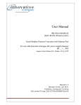
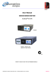
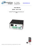
User Manual
+PROTOCONMB
Modbus Protocol Converter
Power Supply Modbus Interface Programmer incl.
Power MBLink v1.3 software
Revision: 3 (07-Jun-11 8:58 AM)
Specifications are subject to change without notice. No liability accepted for errors or omissions.
1
TABLE OF CONTENTS
TABLE OF CONTENTS..........................................................................................................2
INTRODUCTION.....................................................................................................................3
WIRING DIAGRAM .................................................................................................................4
INFORMATION AVAILABLE..................................................................................................5
PROGRAMMING SETUP .......................................................................................................5
SERIAL MODBUS RTU PROTOCOL .....................................................................................9
DIMENSIONS .........................................................................................................................9
COMMUNICATION SETTINGS ............................................................................................ 10
RESETTING TO DEFAULT COMMUNICATION PARAMETERS ......................................... 10
MODBUS REGISTER SET (MODBUS FUNCTIONS 3, 6, 15 & 22)...................................... 11
GENERAL............................................................................................................................. 11
DIGITAL MONITORING ........................................................................................................... 11
Revised Digital Monitoring Bits........................................................................................ 11
Old Digital Monitoring Bits.............................................................................................. 12
DIGITAL CONTROL ................................................................................................................ 13
ANALOGUE PARAMETERS......................................................................................................13
ANALOGUE SETTINGS ........................................................................................................... 14
MODBUS COIL (BIT) SET (MODBUS FUNCTIONS 1, 5 & 15) ............................................ 15
MONITORING ........................................................................................................................ 15
Revised Digital Monitoring Bits........................................................................................ 15
Old Digital Monitoring Bits.............................................................................................. 16
CONTROL ............................................................................................................................ 17
REVISION HISTORY ............................................................................................................ 18
Specifications are subject to change without notice. No liability accepted for errors or omissions.
2
INTRODUCTION
This product must be used with Innovative Energies power supplies and No-BreakTMDC chargers with a RS485 serial
interface.
The ‘Power MBLink’ software is used to configure the Modbus address and baud rate of the interface.
Its primary function is to monitor in real time the various power supply parameters as well as control the battery condition function via the Modbus port. These parameters may also be monitored via the RS232 programming port using a
PC.
Specifications are subject to change without notice. No liability accepted for errors or omissions.
3
WIRING DIAGRAM
Model Codes:
+PROTOCONMB:
+PROTOCONMB-OE:
Modbus RTU on RS485 link
Modbus RTU on RS485 & Modbus
TCP and HTTP over ethernet
+PROTOCONMB
(RS485)
(RS232)
(RS485)
To SRxxx i communication
port
* 1.5m Cat 5e Cable
with RJ45 connector
RJ45
pin #
PD+
PD-
PC
1
2
4
DC input
* 1m x 3c cable with 9
pin serial connector
SR250i power
supply
Rx
9pin
3
female
* Mains power
cable
Tx
Com
2
5
* Power MBLink
software
Alarm outputs
LOAD
Battery
* Accessories included
Specifications are subject to change without notice. No liability accepted for errors or omissions.
4
INFORMATION AVAILABLE VIA MODBUS LINK OR LOCAL PROGRAMMING PORT
Continuously Updated Variables:
Alarm State Signals:
•
•
•
•
•
•
•
•
•
•
•
•
•
Output Voltage
Battery Current
Power Supply Current
Battery Temperature
Alarms
•
•
•
•
•
•
•
•
•
Mains Failure
Possible Mains/PSU Fail
Battery in Bad Condition
Communications to PSU Fail (eg. on LV disconnect)
Overload
System Down
Battery Missing
Battery Low
Possible Battery Missing
Normal Operation
Battery Present
Battery OK (on input power fail)
Battery Charging
Battery Condition Test
BCT enabled
Retry BCT on fail
Battery Discharging
Battery in Good Condition
Command Functions:
•
•
•
•
BCT Enable Acknowledge
BCT Disable Acknowledge
BCT Start Acknowledge
BCT Stop Acknowledge
PROGRAMMING THE PROTOCOL CONVERTER
The protocol converter is supplied with a programming software and programming cable. The software enables the user to set the baud rate and modbus address of the device while also making it possible to monitor the various power supply parameters.
Install Software from disk Power MBLink v1.2 by clicking on Setup.exe
Click Start / ‘All Programs / DoZeener Controls / Innovative Energies Power MBLink v1.2’
The program will begin.
Specifications are subject to change without notice. No liability accepted for errors or omissions.
5
In Communication settings: Click on ‘List Available Ports’
In Communications Setup:
Set Port number to the available ports listed (preferably Port 1) and click Open Com Port. In the notice
section Type should go from Notice to Success
Specifications are subject to change without notice. No liability accepted for errors or omissions.
6
In Converter Information:
Click on Get Specs
When the information is displayed you will have started communications between the module and the
computer.
Then go to: Modbus Monitor TAB and click on Continuous update in Communication.
Specifications are subject to change without notice. No liability accepted for errors or omissions.
7
You will then be able to view the Power Supply Variables and Settings and Diagnostics.
Specifications are subject to change without notice. No liability accepted for errors or omissions.
8
SERIAL MODBUS RTU PROTOCOL
The PROTOCONMB module is compatible with the following Modbus function codes:
01 – Read Coil Status
03 – Read Holding Registers
05 – Force Single Coil
06 – Preset Single Register
15 – Force Multiple Coils
16 – Preset Multiple Registers
22 – Mask Write 4x Register
A maximum
A maximum
A maximum
A maximum
of 80 coils can be polled at one time using function 01
of 32 register can be polled at one time using function 03
of 5 register can be preset at one time using function 06
of 32 coils can be preset at one time using function 15
Modbus ASCII mode is not supported.
DIMENSIONS
25 W x 90 H x 120 D mm
Specifications are subject to change without notice. No liability accepted for errors or omissions.
9
COMMUNICATION SETTINGS
The communication parameters of the protocol converter can be changed via the software “Power MBLink”
The following Baud Rate Settings are possible:
9600
14400
19200
38400
5600
57600
115200
The Modbus slave device also can be changed via the software
Parity can be changed to None, Odd, Even, Space and Mark only to models released after November 2009.
The Data Bits and Stop Bits cannot be changed and are set as 8 and 1 respectively.
RESETTING TO DEFAULT COMMUNICATION PARAMETERS
To reset to the default communication settings of
Modbus address 1
Baud rate 9600
No parity
8 data bits and
1 stop bit
The reset connections RS+ and RS- must be shorted while powering up the device, then removed after
approximately 5 seconds.
Specifications are subject to change without notice. No liability accepted for errors or omissions.
10
MODBUS REGISTER SET (MODBUS FUNCTIONS 3, 6, 15 & 22)
GENERAL
Reference
Watchdog
Modbus
Address
40001
Description
Watchdog
Type
Register
Read
/
Write
R
DIGITAL MONITORING
Revised Digital Monitoring Bits
Modbus Address
Description
Type
Read
/
Write
BCT Related Digitals
40008:1
BCT Active
Bit
R
40008:2
BCT Status(Enabled/Disabled)
Bit
R
40008:3
BCT Start (Acknowledge)
Bit
R
40008:4
BCT Stop (Acknowledge)
Bit
R
40008:5
BCT Enable (Acknowledge)
Bit
R
40008:6
BCT Disable (Acknowledge)
Bit
R
Information Digitals
40009:1
Charge Cycle
Bit
R
40009:2
Battery Ok
Bit
R
40009:3
40009:4
40009:5
Battery Present
Battery Possibly Missing
Possible Mains Fail (Brown Out)
Bit
Bit
Bit
R
R
R
40009:6
Battery Sign (Set for Negative/Discharge)
Bit
R
40009:7
Temperature Sign (Set for Negative)
Bit
R
40009:8
Retry Battery Test on Fail
Bit
R
Alarm Digitals
40010:1
Battery Bad
Bit
R
40010:2
Battery Missing
Bit
R
40010:3
Overload
Bit
R
40010:4
Communications Fail to Power Supply
Bit
R
40010:5
System Down
Bit
R
40010:6
Battery Low
Bit
R
40010:7
Mains Failure
Bit
R
Specifications are subject to change without notice. No liability accepted for errors or omissions.
11
Old Digital Monitoring Bits
The following registers have been replaced with the ones in the previous section ‘Revised digital monitoring
bits’. The digital values in this section provide the same information as the revised ones but have a different
interpretation.
It is recommended that these registers are not used for new applications.
Reference
Modbus
Address
CC
40011:1
Charge Cycle (Normal Operation)
Bit
Read
/
Write
R
OL
40011:2
Overload
Bit
R
MF
40011:3
Mains Failure
Bit
R
BCT
40011:4
Battery Condition Test
Bit
R
BP
40011:5
Battery Present
Bit
R
BM
40011:6
Battery Missing
Bit
R
BL
40011:7
Battery Low
Bit
R
BB
40011:8
Bit
R
M?
40011:9
Battery Bad
Power Supply or Mains Failed (Brown
Out)
Bit
R
Possibly Battery Missing
Bit
R
System Down
Bit
R
Battery OK during mains/psu fail
Bit
R
Battery Condition Test Enabled
Bit
R
Retry Battery Test on Fail
Bit
R
Temperature Sign (1 = Negative, 0 =
Positive)
Bit
R
Battery Current Sign (1 = Out, = 0 In)
Bit
R
B?
SD
BO
Bcond
Ret
TempSign
BatSign
40011:1
0
40011:1
1
40011:1
2
40011:1
3
40011:1
4
40011:1
5
40011:1
6
Description
Type
BCT Start
40012:1
Battery Condition Test Started
Bit
R
BCT Stop
40012:2
Battery Condition Test Stopped
Bit
R
BCT Enable
40012:3
Battery Condition Test Enabled
Bit
R
BCT Disable
40012:4
Bit
R
CommsF
40012:5
Bit
R
b?
40012:9
40012:1
0
40012:1
1
40012:1
2
40012:1
3
Battery Condition Test Disabled
Communications Failure to Power Supply
Possibly Battery Missing (Battery Bad)
Bit
R
Battery Missing (Battery Bad)
Bit
R
Battery OK during mains/psu fail
(Battery Bad)
Bit
R
Battery Low (Battery Bad)
Bit
R
Battery Present (Battery Bad)
Bit
R
bM
bO
bL
bP
Specifications are subject to change without notice. No liability accepted for errors or omissions.
12
DIGITAL CONTROL
Reference
Modbus
Address
BCT Start
40013:1
Start Battery Condition Test
Bit
Read
/
Write
R/W
BCT Stop
40013:2
Stop Battery Condition Test
Bit
R/W
BCT Enable
40013:3
Enable Battery Condition Test
Bit
R/W
BCT Disable
40013:4
Disable Battery Condition Test
Bit
R/W
Type
Read
/
Write
Description
Type
ANALOGUE PARAMETERS
Reference
Modbus
Address
Vout
40014
Ibat
40015
Ipsu
40016
Temp
40017
Description
Output Voltage (Scaled 1:10; 245 = 24.5
Volts)
Battery Current (Scaled 1:10; 123 =
12.3 Amps)
Power Supply Current (Scaled 1:10; 123
= 12.3 Amps)
Register
R
Register
R
Register
R
Temperature (in DegC)
Register
R
Specifications are subject to change without notice. No liability accepted for errors or omissions.
13
ANALOGUE SETTINGS
Type
Read
/
Write
Register
R
Register
R
Register
R
Register
R
Register
R
Register
R
Register
R
Register
R
Time interval between BCTs (in hours)
Register
R
40027
Time interval between BCTs (in days)
Register
R
40028
Mains fail check interval during BCT (in
mins)
Register
R
Reference
Modbus
Address
BatDetect
40018
Vpres
40019
Vshutd
40020
Vbatl
40021
Vdisco
40022
Bccl
40023
BCTim
40024
CC Mins
40025
Time in minutes between battery detect
tests (in mins)
Minimum voltage to detect battery presence (Scaled 1:10 in Volts)
Shutdown Voltage (Scaled 1:10 in
Volts)
Battery low alarm voltage level (Scaled
1:10 in Volts)
Battery disconnect voltage (Scaled 1:10
in Volts)
Battery charge current limit (Scaled
1:10 in Amps)
Length of battery condition test (in
mins)
Time interval between BCTs (in mins)
CC Hrs
40026
CC Days
MfiBCT
Description
Specifications are subject to change without notice. No liability accepted for errors or omissions.
14
MODBUS COIL (BIT) SET (MODBUS FUNCTIONS 1, 5 & 15)
MONITORING
Revised Digital Monitoring Bits
Modbus Address
Description
Type
Read/
Write
BCT Related Digitals
00030
BCT Active
Bit
R
00031
BCT Status(Enabled/Disabled)
Bit
R
00032
BCT Start (Acknowledge)
Bit
R
00033
BCT Stop (Acknowledge)
Bit
R
00034
BCT Enable (Acknowledge)
Bit
R
00035
BCT Disable (Acknowledge)
Bit
R
Information Digitals
00036
Charge Cycle (Normal Operation)
Bit
R
00037
Battery Ok
Bit
R
00038
Battery Present
Bit
R
00039
Battery Possibly Missing
Bit
R
00040
Possible Mains Fail (Brown Out)
Bit
R
00041
Battery Sign (Set for Negative/Discharge)
Bit
R
00042
Temperature Sign (Set for Negative)
Bit
R
00043
Retry Battery Test on Fail
Bit
R
Alarm Digitals
00044
Battery Bad
Bit
R
00045
Battery Missing
Bit
R
00046
Overload
Bit
R
00047
Communications Fail to Power Supply
Bit
R
00048
System Down
Bit
R
00049
Battery Low
Bit
R
00050
Mains Failure
Bit
R
Specifications are subject to change without notice. No liability accepted for errors or omissions.
15
Old Digital Monitoring Bits
The following coils have been replaced with the ones in the previous section ‘Revised digital monitoring
bits’. The digital values in this section provide the same information as the revised ones but have a different interpretation.
It is recommended that these coils are not used for new applications.
CC
Modbus
Address
00001
Charge Cycle (Normal Operation)
Bit
Read
/
Write
R
OL
00002
Overload
Bit
R
MF
00003
Mains Failure
Bit
R
BCT
00004
Battery Condition Test
Bit
R
BP
00005
Battery Present
Bit
R
BM
00006
Battery Missing
Bit
R
BL
00007
Battery Low
Bit
R
BB
00008
Bit
R
M?
00009
Bit
R
B?
00010
Battery Bad
Power Supply or Mains Failed (Brown
Out)
Possibly Battery Missing
Bit
R
SD
00011
System Down
Bit
R
BO
00012
Battery OK during mains/psu fail
Bit
R
Bcond
00013
Battery Condition Test Enabled
Bit
R
Ret
00014
Retry Battery Test on Fail
Bit
R
TempSign
00015
Temperature Sign (1 = Negative, 0 =
Positive)
Bit
R
BatSign
00016
Battery Current Sign (1 = Out, = 0 In)
Bit
R
BCT Start
00017
Battery Condition Test Started
Bit
R
BCT Stop
00018
Battery Condition Test Stopped
Bit
R
BCT Enable
00019
Battery Condition Test Enabled
Bit
R
BCT Disable
00020
Bit
R
CommsF
00021
Bit
R
b?
00022
Battery Condition Test Disabled
Communications Failure to Power Supply
Possibly Battery Missing (Battery Bad)
Bit
R
bM
00023
Battery Missing (Battery Bad)
Bit
R
bO
00024
Battery OK during mains/psu fail
(Battery Bad)
Bit
R
bL
00025
Battery Low (Battery Bad)
Bit
R
bP
00026
Battery Present (Battery Bad)
Bit
R
Reference
Description
Specifications are subject to change without notice. No liability accepted for errors or omissions.
Type
16
CONTROL
BCT Start
Modbus
Address
00065
Start Battery Condition Test
Bit
Read
/
Write
R/W
BCT Stop
00066
Stop Battery Condition Test
Bit
R/W
BCT Enable
00067
Enable Battery Condition Test
Bit
R/W
BCT Disable
00068
Disable Battery Condition Test
Bit
R/W
Reference
Description
Specifications are subject to change without notice. No liability accepted for errors or omissions.
Type
17
REVISION HISTORY
Revision
Number
Date Revised
Revised
By
1
10-Jun-08
RM
Initial Revision
2
16-Jun-09
RM
Reformatted Document and programming cable wiring information
3
9-Jul-10
RM
Added revised digital monitoring set
Description
Specifications are subject to change without notice. No liability accepted for errors or omissions.
18