1
SMT Array Design
TECH NOTE
5.4 Detailed Planarity Measurements
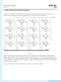
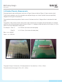
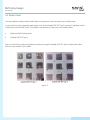
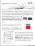
Prototype boards were manufactured, as shown in Figure 9 (sensor side) and Figure 10 (rear connector side).
To fully test the planarity, one of the samples was analyzed using a non-contact optical instrument specifically
designed for this type of measurement.
The machine first takes the position of each corner of the board and from 2 diagonal lines it calculates the ideal
plane.
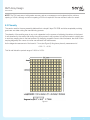
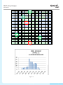
The position of the surface of each sensor pixel is then measured and compared with the ideal plane. An example
result from one of the prototype arrays is shown in Figure 11. It displays a value that tells you how close (+ or -) the
device is from the ideal plane for each pixel.
For example: Pixel 111 Pixel 80 is +0.005mm (5um above the ideal plane)
is -0.013mm (13um below the ideal plane)
Blue = +ve = ABOVE
Green = -ve = BELOW
Figure 9
Figure 10
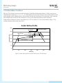
The graph in Figure 12 shows the 144 values placed in 10um bins from -100 to +100um.
The results shows the range is -80 to +60 = 140um.
SensL © 2012
10