1
Ansur Index 2XL
Plug-In
Users Manual
April 2010, Rev. 1
© 2010 Fluke Corporation. All rights reserved.
All product names are trademarks of their respective companies.
Table of Contents
Chapter
1
Title
Introduction ......................................................................................... 1-1
About This Manual ............................................................................................
Ansur Software ..................................................................................................
Ansur Plug-Ins ...................................................................................................
Index 2XL Plug-In.........................................................................................
Additional References ...................................................................................
Software Updates ...............................................................................................
Terms and Abbreviations...................................................................................
2
1-3
1-3
1-3
1-3
1-4
1-4
1-5
Getting Started .................................................................................... 2-1
Introduction........................................................................................................
System Requirements ........................................................................................
Installing the Index 2XL Plug-In .......................................................................
Entering the License Key ..............................................................................
Uninstalling the Plug-In ................................................................................
Ansur Main Window .........................................................................................
Test Explorer .................................................................................................
Viewing Available Test Elements .................................................................
Selecting Plug-In Preferences ............................................................................
Oximeter Make Name ...................................................................................
Viewing a Custom R-Curve ......................................................................
Synchronizing custom R-Curves in the Plug-In with the Simulator .........
Defining a New (Custom) Oximeter .............................................................
Editing a Previously Programmed Custom R-Curve ................................
Deleting a Custom R-Curve ......................................................................
Loading a Custom R-Curve into the Simulator.........................................
3
Page
2-3
2-3
2-3
2-4
2-5
2-6
2-6
2-6
2-7
2-7
2-8
2-8
2-8
2-11
2-12
2-12
Index 2XL Tests ................................................................................... 3-1
Introduction........................................................................................................
Ansur Test Guide ...............................................................................................
Running an SpO2 Finger Simulation Test .........................................................
Running Probe Tests ..........................................................................................
LED Test .......................................................................................................
i
3-3
3-3
3-4
3-5
3-5
Ansur Index 2XL
Users Manual
Photodiode Test ............................................................................................. 3-5
Resistance Test .............................................................................................. 3-6
4
Index 2XL Test Templates .................................................................. 4-1
Introduction........................................................................................................
Creating Test Templates ....................................................................................
Using Index 2XL Test Elements........................................................................
SpO2 Simulation Test....................................................................................
LED Test .......................................................................................................
Photodiode Test .............................................................................................
Resistance Test ..............................................................................................
ii
4-3
4-3
4-5
4-5
4-6
4-6
4-6
List of Tables
Table
1-1.
2-1.
4-1.
4-2.
4-3.
4-4.
4-5.
Title
Terms and Abbreviations .......................................................................................
Example Custom Oximeter Details........................................................................
SpO2 Simulation Test Measurements ....................................................................
SpO2 Simulation Test Custom Parameters ............................................................
LED Test Measurements........................................................................................
Photodiode Test Measurements .............................................................................
Resistance Test Measurements...............................................................................
iii
Page
1-5
2-10
4-5
4-6
4-6
4-6
4-6
Ansur Index 2XL
Users Manual
iv
List of Figures
Figure
2-1.
2-2.
2-3.
2-4.
2-5.
2-6.
2-7.
2-8.
2-9.
2-10.
2-11.
2-12.
2-13.
2-14.
3-1.
3-2.
3-3.
4-1.
4-2.
4-3.
4-4.
4-5.
Title
Entering the Registration License Key...................................................................
Removing Index 2XL Plug-In................................................................................
Index 2XL Main Application Window ..................................................................
Index 2XL Test Explorer Window.........................................................................
Index 2XL SpO2 Simulator Preferences ................................................................
View Custom R-Curve window .............................................................................
Missing Custom R-Curve in the Simulator ............................................................
Custom R-Curve window.......................................................................................
Custom R-Curve Generator window......................................................................
Save Oximeter As… window.................................................................................
Overwrite Dialog Box ............................................................................................
Delete Oximeter Dialog Box..................................................................................
R-Curve Save Error Dialog Box ............................................................................
R-Curve Saving Location Dialog Box ...................................................................
Ansur Test Guide Window.....................................................................................
Help Pane in Ansur Test Guide Window ...............................................................
Custom R-Curve Location Selection Dialog..........................................................
Test Template with Selected Test Element ............................................................
User-Definable Parts of the General Setup Tab .....................................................
Expected Results Options for User Input ...............................................................
Pop-Up Menu for Adding or Deleting Limits ........................................................
Custom Setup Page for SpO2 Simulator Test Element..........................................
v
Page
2-4
2-5
2-6
2-6
2-7
2-8
2-8
2-9
2-10
2-11
2-12
2-12
2-13
2-13
3-3
3-4
3-4
4-3
4-4
4-4
4-4
4-5
Ansur Index 2XL
Users Manual
vi
Chapter 1
Introduction
Title
Page
About This Manual ..............................................................................................1-3
Ansur Software ....................................................................................................1-3
Ansur Plug-Ins .....................................................................................................1-3
Index 2XL Plug-In...........................................................................................1-3
Additional References .....................................................................................1-4
Software Updates .................................................................................................1-4
Terms and Abbreviations ................................................................................1-5
1-1
Ansur Index 2XL
Users Manual
1-2
Introduction
About This Manual
1
About This Manual
This Users Manual explains how to use the Ansur Index 2XL Plug-In with Ansur
software. The manual covers all features specific to the Plug-In. Familiarity with both
Ansur software and Microsoft Windows and their features will help in the design and use
of automated tests for the Fluke Biomedical Model Index 2XL SpO2 Simulator, hereafter
called the "Simulator." The Simulator tests fingertip pulse-oximeters by simulating a
human finger ("Index" refers to index finger) with a selected SPO2 (saturated peripheral
oxygen) level and pulse rate.
This manual is divided into the following chapters:
Chapter 1 “Introduction” provides general information on Ansur software, the Index
2XL Plug-In and how to use this manual.
Chapter 2 “Getting Started” provides information on how to install and configure the
Index 2XL Plug-In, and how to create a custom R-Curve for a non-supported
oximeter.
Chapter 3 “Index 2XL Tests” provides step-by-step descriptions on how to use the
Index 2XL Plug-In to design basic automated tests for use with the Simulator.
Chapter 4 “Index 2XL Templates” contains information on creating highly efficient
automated test procedures using the Index 2XL Plug-In template functionality.
Ansur Software
Ansur Test Automation software is the umbrella name of the Ansur Test Executive core
software plus Analyzer or Simulator-specific Plug-Ins for various Fluke Biomedical test
instruments, such as the Index 2XL SpO2 Simulator. Ansur manages test procedures by
allowing both manual and visual automated test sequences.
The software works hand-in-hand with Fluke Biomedical analyzers and simulators,
creating a seamless integration for:
•
•
•
•
•
Visual inspections
Preventive maintenance
Work procedures
Performance tests
Electrical safety tests
Ansur Plug-Ins
Ansur Test Executive software utilizes Plug-In modules that work with a wide array of
Fluke Biomedical instruments. The Plug-In module is a software interface that provides
test elements for a specific analyzer or a simulator to the Ansur Test Executive program.
This scheme allows the use of a similar user interface for all analyzers and simulators
supported by Ansur.
With the purchase of a new Fluke Biomedical analyzer or simulator, it is possible to
update existing Ansur software by installing a new Plug-In. Each Plug-In module allows
users to work with only the options and capabilities needed for the instrument under test.
Index 2XL Plug-In
The Ansur Index 2XL Plug-In provides remote access to the Index 2XL SpO2 Simulator,
referred to throughout this document as the “Simulator.” In addition to the general test
plug-ins, specialized plug-ins address all test requirements for specific instruments.
1-3
Ansur Index 2XL
Users Manual
Note
The Index 2XL SpO2 Simulator Users Manual explains the Simulator’s
capabilities and use.
Create and use Ansur test procedures with Ansur Index 2XL test elements to incorporate
the capabilities of a Simulator into automated testing. Users can customize tests to
analyze specific performance requirements. There are unique test elements for each of the
tests. Simulations typically run on the Simulator.
Additional References
In addition to this manual, answers to questions about using the Simulator or PC may be
found in the following sources:
•
Fluke Biomedical Index 2XL SpO2 Simulator Users Manual
•
Fluke Biomedical Ansur Test Executive Users Manual
•
Microsoft Windows Help and Support Center
Software Updates
Updates for Ansur software are published for download on the Fluke Biomedical website,
http://www.flukebiomedical.com
1-4
Introduction
Terms and Abbreviations
1
Terms and Abbreviations
Table 1-1 lists terms and abbreviations used in this manual.
Table 1-1. Terms and Abbreviations
Term
Description
Ansur
Ansur is a software suite using plug-ins to perform or automate test and inspection
procedures in conjunction with several Fluke Biomedical test instruments.
DUT
Device Under Test—the equipment subjected to a test using the Simulator.
DUT Info
Information used to identify one particular DUT. DUT info usually consists of a serial
number, manufacturer, device type and model. Ansur also adds a few extra data
fields such as location and status.
Index 2XL
SpO2 Simulator from Fluke Biomedical -- "Index" refers to index finger, and "SpO2"
refers to saturation of peripheral oxygen. This device tests fingertip pulse oximeters.
Field User
The person using Ansur to perform a test template on a DUT.
Module Setup
Module setup contains information about probes connected to the Simulator to test
one specific DUT.
Plug-In
Add-on software program that extends Ansur so that it can interface with a specific
Fluke Biomedical test instrument to configure it for a specific test and to
automatically run tests and record the results (if applicable)
Test Container
A test container is a test element that can contain other test elements. The Index
2XL Auto Sequence is a test container.
Test Element
An Ansur construct that encapsulates test configuration and results.
A test template is built of several test elements.
Test Guide
Test Record
A window displayed by Ansur or any of its plug-ins when a test element is being
performed.
An Ansur file containing the results of a performed test template
The test record can be printed as a test report.
Test Template
An Ansur file containing a set of test elements that define how a particular DUT is to
be tested.
A test template can also contain instructions on how to perform service, preventive
maintenance, repair, and other tasks on a DUT.
1-5
Ansur Index 2XL
Users Manual
1-6
Chapter 2
Getting Started
Title
Introduction..........................................................................................................
System Requirements ..........................................................................................
Installing the Index 2XL Plug-In .........................................................................
Entering the License Key ................................................................................
Uninstalling the Plug-In ..................................................................................
Ansur Main Window ...........................................................................................
Test Explorer ...................................................................................................
Viewing Available Test Elements ...................................................................
Selecting Plug-In Preferences ..............................................................................
Oximeter Make Name .....................................................................................
Viewing a Custom R-Curve ........................................................................
Synchronizing custom R-Curves in the Plug-In with the Simulator ...........
Defining a New (Custom) Oximeter ...............................................................
Editing a Previously Programmed Custom R-Curve ..................................
Deleting a Custom R-Curve ........................................................................
Loading a Custom R-Curve into the Simulator...........................................
Page
2-3
2-3
2-3
2-4
2-5
2-6
2-6
2-6
2-7
2-7
2-8
2-8
2-8
2-12
2-12
2-12
2-1
Ansur Index 2XL
Users Manual
2-2
Getting Started
Introduction
2
Introduction
This chapter describes installation of the Index 2XL Plug-In and its use together with
Ansur software and the Index 2XL SpO2 Simulator instrument from Fluke Biomedical.
Note
A Simulator is not necessary to create test templates and experiment with
the functionality available in Ansur and the Index 2XL Plug-In. However,
actual tests cannot be performed unless the Simulator is connected to the
computer.
System Requirements
The following are recommended minimum requirements for installation:
•
•
•
•
•
•
IBM PC/XT-compatible Pentium II 350 MHz or faster processor
128 MB of RAM
Microsoft® Windows® 2000 or Windows® XP or Windows® Vista or
Windows® 7 operating system
Fluke Biomedical Ansur V2.9.0 or newer
50 MB of available hard drive for software
Hard drive space (from 100 kB to several MB) for result and template files
Installing the Index 2XL Plug-In
The Index 2XL Plug-In must be installed on the computer that has Ansur software
already installed on it before the features described in this user manual can be used. For
information on obtaining the Ansur software and the Index 2XL Plug-In, contact your
local Fluke Biomedical representative or visit the Fluke Biomedical website at
http://www.flukebiomedical.com.
Note
Ansur version 2.9.0 or newer must be installed before the Index 2XL PlugIn is installed and used.
Download the Index 2XL Plug-In from the Fluke Biomedical website and follow the
steps below:
Note
When downloading the Index 2XL Plug-In from the Fluke Biomedical
website, it is possible to run the installation without first downloading. But
these instructions assume downloading the installation package and then
running it from the local PC.
Note
When installing Ansur or any of its components/plug-ins on computers
running Microsoft Vista, it is important to perform the installation as the
Administrator for that computer. Otherwise the registry will not be properly
updated and Ansur will not work properly. For installing on Windows
Vista, you must first download the file to your local computer, then locate
the installation file, right click and select “Run as Administrator.”
1. Open Windows Explorer and browse to the saved Index 2XL Plug-In installation
program file, usually named Ansur Index 2XL Plug-In Vn.n.n.exe, where n.n.n
is the Plug-In version number.
2. Double-click the installation program. The installation extracts the Plug-In elements
and displays the Welcome dialog box.
2-3
Ansur Index 2XL
Users Manual
3. Click Next to display the license agreement.
4. Select the checkbox for “I accept the terms in the license agreement,” and
click Next to display the default destination folder.
5. Choose one of the following options:
•
Click Next to accept the default destination folder in which Ansur was installed.
•
Click Change if Ansur has been installed in a different folder. In this case, the
destination folder for the Plug-In is changed so that it resides in the same
directory as the Ansur program.
Note
If Ansur has been installed in a different destination folder from the default,
be sure to use the same folder for the Index 2XL Plug-In.
6. Click Install to begin the installation. A progress bar indicates the status of the PlugIn installation.
After a few minutes, the installation concludes, and the window displays the dialog
box and the Finish button.
7. Click Finish. The Plug-In will load when Ansur is started.
Entering the License Key
When using the Plug-In for the first time, the user is prompted to enter a software license
key provided by Fluke Biomedical at the time of purchase.
Note
Test templates can be created without a license key by using the
demonstration (Demo) mode. Demonstration mode allows many of the tasks
described in this user manual. However, a user may not save or print
without licensing the Plug-In.
1. Start Ansur by doing one of the following:
•
Double-click the Ansur icon on the desktop.
•
From the Start menu, select Start | Programs | Fluke | Ansur.
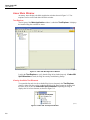
Note
The license key dialog box shown in Figure 2-1 appears at startup if a
license key has not yet been entered for the Plug-In.
Figure 2-1. Entering the Registration License Key
2-4
git001.bmp
Getting Started
Installing the Index 2XL Plug-In
2
2. Enter the Establishment name and the plug-in License key. If the License key is
not available, click the Demo button to start Ansur in Demo mode.
Note
Because the license key is derived from the establishment name, both
strings must match the license information provided by Fluke Biomedical.
This information is case sensitive and space sensitive. If the establishment
name has been entered in the past, this field is already filled in.
3. Click OK to start Ansur.
4. Click Cancel to prevent the Plug-In from being loaded.
Uninstalling the Plug-In
To uninstall the Index 2XL Plug-In:
1. Select Start | Control Panel and double-click Add or Remove Programs.
2. Locate and select the entry named Ansur Index 2XL Plug-in, as shown in
Figure 2-2.
Figure 2-2. Removing Index 2XL Plug-In
git023.bmp
3. Click on the Remove button.
4. When asked to verify the removal, click Yes. A dialog box with a progress bar
displays while the Index 2XL Plug-In is being removed from the computer.
When the Plug-In is no longer listed in the Add or Remove Programs window, it
has been completely removed.
2-5
Ansur Index 2XL
Users Manual
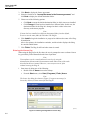
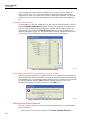
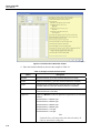
Ansur Main Window
At startup, Ansur displays the Main Application window shown in Figure 2-3. Test
templates can be created and edited from this window.
Test Explorer
The left pane of the Main Application window is called the Test Explorer. It displays
the installed Plug-Ins available in Ansur.
Figure 2-3. Index 2XL Main Application Window
git002.bmp
Look in the Test Explorer to verify that the Plug-In has loaded properly. If Index 2XL
SpO2 Simulator is listed, the Plug-In correctly loaded during startup.
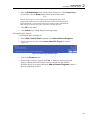
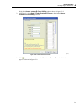
Viewing Available Test Elements
To expand the list and view the available Plug-In test elements in the Test Explorer
window, either click the + (plus) symbol to the left of the Plug-In name or double-click
the name itself; in this case Index 2XL SpO2 Simulator. Expanding the Plug-In
displays the list of test elements, as shown in Figure 2-4.
Figure 2-4. Index 2XL Test Explorer Window
2-6
git003.bmp
Getting Started
Selecting Plug-In Preferences
2
Selecting Plug-In Preferences
Note
If the Index 2XL SpO2 Simulator is not connected to COM1 on the PC,
Ansur displays an Instrument Not Found window where the port the
Simulator is connected to can be entered. The correct port number is
displayed in the Windows Device Manager. Look for the USB Serial Port
entry under “Ports.”
Once the PC locates which port the Simulator is connected to, Ansur
remembers the port number and uses it as the default port for electrical
safety tests.
Use Plug-In Preferences to choose default settings that best suit how you plan to use the
Plug-In with the Simulator. Defaults define the start-up condition of most pulse oximeter
performance testing features.
To change Plug-In Preferences:
1. Start the Ansur Test Executive program.
2. Click Tools | Options to display the Preferences window shown in Figure 2-5.
Figure 2-5. Index 2XL SpO2 Simulator Preferences
git004.bmp
3. Click the Index 2XL SpO2 Simulator icon. The window displays the Default
settings. In this window you can select oximeter make, view create custom R-curves,
and if using custom R-curves, send the custom R-Curves to the Simulator before
performing the test.
4. Click OK.
Oximeter Make Name
There are 10 standard oximeter makes available in the Simulator Preferences window.
They are:
•
•
•
•
•
BCI
Criticare
Datascope
Datex
PMS M1190
•
•
•
•
•
Masimo
Nellcor
Nihon-Kohden
Ohmeda & Nova
Respironics
2-7
Ansur Index 2XL
Users Manual
The six predefined oximeter makes for which you can view the R-Curve details are:
Invivo, M1190, M1191, N-10, Nonin, and PALCO. Instructions later in this chapter
explain how to create your own R-Curves and save them in the Simulator. Any optional
custom R-Curves you create and name, appear in the Oximeter make name dropdown
list.
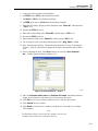
Viewing a Custom R-Curve
If a custom R-Curve has been established, you can select the custom oximeter’s R-Curve
from the Oximeter make name dropdown list and view the details. You cannot view
R-Curves of the standard oximeter make names supplied with the Plug-In. If there are
any custom R- Curves, click the View R-Curve button to view the custom R-Curve
details as displayed in Figure 2-6. You cannot edit the Oximeter Details and the R-Curve
values in this window. Editing these values is explained later in this manual.
Figure 2-6. View Custom R-Curve window
git005.bmp
Synchronizing custom R-Curves in the Plug-In with the Simulator
If the error message in Figure 2-7 appears while the PC is connected to the Simulator, it
means that the Plug-In has a custom R-Curve programmed that has not been downloaded
to the Simulator yet. To remedy the situation, make sure there is connectivity between the
PC and the Simulator and click Yes to send the selected custom R-Curve to the
Simulator and continue to prepare to do a test or Click No to exit.
Figure 2-7. Missing Custom R-Curve in the Simulator
git006.bmp
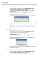
Defining a New (Custom) Oximeter
To create your own oximeter R- Curves and send the custom R-Curves to the Simulator,
proceed as follows:
1. Start the Ansur Test Executive program. Click Tools | Custom R-Curve to
2-8
Getting Started
Selecting Plug-In Preferences
2
display the Ansur Custom R-Curve Utility window shown in Figure 2-8.
2. Alternatively, select Start | Fluke | Custom R-Curve to display the Ansur
Custom R-Curve Utility window.
Figure 2-8. Custom R-Curve window
git007.bmp
3. Click
to create a new oximeter. The “Custom R-Curve Generator” window
appears as shown in Figure 2-9.
2-9
Ansur Index 2XL
Users Manual
Figure 2-9. Custom R-Curve Generator window
git008.bmp
4. Enter the Oximeter Details as shown in the example in Table 2-1.
Table 2-1. Example Custom Oximeter Details
Option
Description
Red DC
Red Transmissivity. (The value should be between 0 and 4095)
IR DC
Infrared Transmissivity. (The value should be between 0 and 4095)
IR AC
Infrared light AC amplitude peak-to-peak attenuation for the pulse
oximeter under test. (The value should be between 0 and 4095)
TLC
Transmission Control Level for the pulse oximeter under test. (The value
should be between 0 and 4095)
Light level
Light level, Medium or Low. The light level is organized into six download
slots as
Download Slot 1 = Medium Light
Download Slot 2 = Medium Light
Download Slot 3 = Medium Light
Download Slot 4 = Medium Light
Download Slot 5 = Low Light
Download Slot 6 = Low Light
Note
Custom R-Curve will not produce the desired results if RCurve is saved in the wrong slot.
2-10
Getting Started
Selecting Plug-In Preferences
2
5. Connect the pulse oximeter to the Simulator.
6. Set RVAL step to 0.010 in the Simulator manually.
7. Set SpO2 to 100% in the Simulator manually.
8. Set BPM (pulse rate) to 100 BPM in the Simulator manually.
9. Enter the first reading, displayed in the Simulator in the “Value #1” column against
“100%” row.
10. Increase the RVAL by 0.010
11. Enter the second reading in the “Value #2” column against “100%” row.
12. Increase the RVAL by 0.010
13. Enter the third reading in the “Value #3” column against “100%” row.
14. The Average R-value is calculated and displayed in the “Avg. Value” column.
15. Now, decrement the SpO2 by 1. Repeat the steps from step 8 to step 13 entering the
Value #1, Value #2, and Value #3 against the set SpO2 value until the SpO2 reaches
50%.
16. After completing the steps, click Save button to save the file. Save Oximeter
As… window appears as shown in Figure 2-10.
Figure 2-10. Save Oximeter As… window
git009.bmp
17. Enter the Oximeter make name and Oximeter file name. (Maximum character
length is 9 for Oximeter make name and 16 for Oximeter file name)
18. Click OK to save the new custom oximeter R-Curve and close the window.
19. Click Cancel close the window.
20. Click Send in Custom R curve window to send the new custom R-Curve to Index
2XL simulator.
Note
The Simulator must be connected to the computer with a serial
communication cable before sending the R-Curve.
2-11
Ansur Index 2XL
Users Manual
Editing a Previously Programmed Custom R-Curve
To edit a custom R-Curve:
1. Start the Ansur Test Executive program. Click Tools | Custom R-Curve to
display the Custom R-Curve window shown in Figure 2-8.
Alternatively, select Start | Fluke | Custom R-Curve to display the Ansur
Custom R-Curve window.
2. Choose the required R-Curve from the Custom R-curve dropdown list.
3. Edit the Oximeter details and R-Value if necessary.
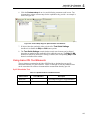
4. Click Save. An Overwrite confirmation dialog box appears as shown in Figure 2-11.
Figure 2-11. Overwrite Dialog Box
git010.bmp
5. Click Yes to overwrite the data for the oximeter. A Save dialog box appears. Click
OK.
6. Click No to save the changes as a new oximeter R-Curve. Save Oximeter As…
window appears. Enter the new Oximeter make name and Oximeter file name. Click
OK.
Deleting a Custom R-Curve
To delete a custom R-Curve, proceed as follows:
1. Start the Ansur Test Executive program. Click Tools | Custom R-Curve to
display the Custom R-Curve window shown in Figure 2-8.
Alternatively, select Start | Fluke | Custom R-Curve to display the Ansur
Custom R-Curve window.
2. Choose the required oximeter R-Curve from the Custom R-Curve dropdown list.
3. Click
to delete the selected oximeter R-Curve. A conformation dialog box
appears as shown in Figure 2-12.
Figure 2-12. Delete Oximeter Dialog Box
git011.bmp
4. Click Yes, to delete the selected oximeter R-Curve. Click No if you do not want to
delete the oximeter R-Curve.
Loading a Custom R-Curve into the Simulator
To load a custom R-Curve into Index 2XL SpO2 Simulator:
1. Start the Ansur Test Executive program. Click Tools | Custom R-Curve to
display the Custom R-Curve window shown in Figure 2-8.
2. Alternatively, select Start | Fluke | Custom R-Curve to display the Ansur
2-12
Getting Started
Selecting Plug-In Preferences
2
Custom R-Curve window.
3. Choose the required R-Curve from the Custom R-Curve dropdown list.
4. Click Send to send the selected R-Curve to the Simulator.
Note
If you try to send the R-Curve to the Simulator without first saving it in the
Plug-In, the “Save” dialog box appears as shown in Figure 2-13. If this
happens, Click Yes to first save the customer R-Curve information in the
Plug-In.
Figure 2-13. R-Curve Save Error Dialog Box
git012.bmp
5. When sending the R-Curve to the Simulator, a Location dialog box appears as
shown in Figure 2-14 for you to select the location in the Simulator for the R-Curve.
Figure 2-14. R-Curve Saving Location Dialog Box
git013.bmp
6. Six locations are available to choose from in the Select location dropdown list,
depending on the Light level selected in Custom R-Curve Generator window.
•
If the Light level is Medium, locations are Custom #1, Custom #2, Custom #3,
and Custom #4.
•
If the Light level is Low, locations are Custom #5, and Custom #6.
7. Choose the location and click OK.
8. A dialog box announces successful downloading to the Simulator if communication
has been established. Click OK again to complete the download process.
2-13
Ansur Index 2XL
Users Manual
2-14
Chapter 3
Index 2XL Tests
Title
Introduction..........................................................................................................
Ansur Test Guide .................................................................................................
Running an SpO2 Finger Simulation Test ...........................................................
Running Probe Tests ............................................................................................
LED Test .........................................................................................................
Photodiode Test ...............................................................................................
Resistance Test ................................................................................................
Page
3-3
3-3
3-4
3-5
3-5
3-5
3-6
3-1
Ansur Index 2XL
Users Manual
3-2
Index 2XL Tests
Introduction
3
Introduction
This chapter describes how to use the Ansur Index 2XL Plug-In program to automate
testing of pulse oximeters with the Index 2XL SpO2 Simulator. Disconnect the Index
2XL from the computer first if you decide to operate the Simulator from the front panel.
If you don’t, the Index 2XL LCD will refresh.
Ansur Test Guide
This manual includes tests unique to the Plug-In for the Simulator. For overall
information on selecting and executing tests with Ansur software, please refer to the
latest version of the Ansur Executive Users Manual.
When a test is executed with the Index 2XL Plug-in, the TEST GUIDE window opens.
Use the TEST GUIDE to step through each element in the test procedure.
The TEST GUIDE has a:
•
Center pane that displays either the default explanation or one entered when a
custom template was created.
•
Test results pane that displays results of the test being run.
For the Index 2XL Plug-In, when you execute a test, the MTI data pane appears by
default as shown in Figure 3-1.
Figure 3-1. Ansur Test Guide Window
git015.bmp
Enter the MTI Data as follows:
1. Select the MTI type from the dropdown list.
•
For SpO2 Simulation test, Index 2XL FE or Index 2XL F type are available.
•
For Probe Tests, only Index 2XL FE type is available.
2. Enter the Serial number and Firmware version.
3. Click
to view the instructions to perform a particular test as shown in Figure 3-2.
3-3
Ansur Index 2XL
Users Manual
Figure 3-2. Help Pane in Ansur Test Guide Window
git016.bmp
4. Click Start on the TEST GUIDE toolbar to begin the test. Simulator starts
simulating the results appear in the Oximeter. User has to enter results in the Test
results pane.
Running an SpO2 Finger Simulation Test
To run an SpO2 finger stimulation test, proceed as follows:
1. Connect the finger probe of the pulse oximeter under test to the Index 2XL finger
probe attachment. Position the pulse oximeter LEDs on the bottom of Index 2XL's
finger probe attachment.
2. Click Start in the TEST GUIDE toolbar.
3. If the option Send custom R-Curve to Index 2XL before performing the
test in Custom setup page is selected or the Index 2XL Plug-In cannot locate the
custom R-curve selected in Custom setup page, the message in Figure 3-3 appears.
Figure 3-3. Custom R-Curve Location Selection Dialog
git017.bmp
4. Six locations are available to choose from in the Select location dropdown list,
depending on the Light level selected in Custom R-Curve Generator window.
•
If the Light level is Medium, locations are Custom #1, Custom #2, Custom #3,
and Custom #4.
•
If the Light level is Low, locations are Custom #5, and Custom #6.
5. Choose the location and click OK.
6. Note the SpO2 and BPM reading.
7. Enter the SpO2 and BPM values observed on the Oximeter monitor.
3-4
Index 2XL Tests
Running Probe Tests
3
If at least one of the SpO2 and BPM values is outside the limits specified in the test
procedure, the test is marked as failed.
8. Click Next to proceed or click Start to run the test again.
9. Click Stop in the TEST GUIDE toolbar to conclude the test.
Electrical testing of oximeters is similar to optical testing, except all simulations are
output through the electrical port on the back of the Index 2. This eliminates the probe
from the circuit.
Running Probe Tests
Index 2XL allows you to verify the electrical continuity and integrity of most oximeter
probes.
To run a Probe Test:
1. Connect the probe under test to the back of the Index 2XL using the appropriate
adapter cable. Refer to the Index 2XL Users Manual for connection instructions.
Note
During the Photodiode and resistance test, the finger probe being tested
should not be attached to the Index 2XL finger.
2. Click Start in the TEST GUIDE toolbar.
When the Simulator completes its measurements, Ansur retrieves the results from the
Simulator and displays them in the Test Results pane.
If at least any one of the result parameter is outside the limits specified in the test
procedure, the test is marked as failed.
3. Click Next to proceed or click Start to run the test again.
LED Test
To run an LED Test:
1. Connect the probe under test to the back of the Index 2XL using the appropriate
adapter cable, and connect the sensor to the artificial finger of the Simulator. Refer to
the Index 2XL Users Manual for connection instructions.
2. Click Start in the TEST GUIDE toolbar.
If at least one of the Red LED (LEDs - R), IR LED (LEDs - IR), and PHTO LED
(LEDs - PHTO) values is outside the limits specified in the test procedure, the test is
automatically marked as "failed."
3. Click Next to proceed or click Start to run the test again.
4. Click Stop in the TEST GUIDE toolbar to conclude the test.
Photodiode Test
In the Photodiode Test, results close to zero support a faulty probe diagnosis. To run a
Photodiode Test:
1. Connect the probe under test to the back of the Index 2XL using the appropriate
adapter cable. Refer to the Index 2XL Users Manual for connection instructions.
Note
For the Photodiode test, do not attach the finger probe being tested to the
Index 2XL finger.
2. Click Start in the TEST GUIDE toolbar.
3-5
Ansur Index 2XL
Users Manual
If at least any one of the Red Photodiode (Photodiode - R) and IR Photodiode
(Photodiode -IR) values are outside the limits specified in the test procedure, the test
is marked as failed.
3. Click Next to proceed or click Start to run the test again.
4. Click Stop in the TEST GUIDE toolbar to conclude the test.
Resistance Test
To run a Resistance Test:
1. Connect the probe under test to the back of the Index 2XL using the appropriate
adapter cable. Refer to the Index 2XL Users Manual for connection instructions.
Note
For the Resistance test, do not attach the finger probe being tested to the
Index 2XL finger.
2. Click Start in the TEST GUIDE toolbar.
If at least any one of the Resistance values between the wires selected is outside the
limits specified in the test procedure, the test is marked as failed.
3. Click Next to proceed or click Start to run the test again.
4. Click Stop in the TEST GUIDE toolbar to conclude the test.
3-6
Chapter 4
Index 2XL Test Templates
Title
Introduction..........................................................................................................
Creating Test Templates ......................................................................................
Using Index 2XL Test Elements..........................................................................
SpO2 Simulation Test......................................................................................
LED Test .........................................................................................................
Photodiode Test ...............................................................................................
Resistance Test ................................................................................................
Page
4-3
4-3
4-5
4-5
4-6
4-6
4-6
4-1
Ansur Index 2XL
Users Manual
4-2
Index 2XL Test Templates
Introduction
4
Introduction
This chapter introduces the specific template capabilities of the Index 2XL Plug-In and
provides guidance for customizing test templates. General information on creating Ansur
test templates can be found in the Ansur Test Executive User Manual.
Creating Test Templates
Create, modify, and review test templates using the Ansur Main Application window
as a template editor. The Index 2XL Plug-In provides two test elements that are used to
build new test procedures. These are accessible in the Test Explorer and are coded as
follows:
•
Light blue icon – the Detector automatically provides test result data to Ansur as
the test is completed.
•
Yellow icon – resultant data must be manually entered into Ansur by the user.
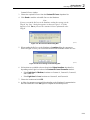
To build a test template, take the following actions, beginning at the Main Application
window:
1. Drag a test element from the Test Explorer (left pane) into the Test Template
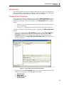
(right pane), as displayed in Figure 4-1. Clicking the test element in the Test
Template highlights the test element and its properties. In this illustration, the
highlighted element is the Index 2XL SpO2 Simulation Test, and is the first test
step to be performed.
Figure 4-1. Test Template with Selected Test Element
git018.bmp
In the middle of the Test Template window are located the following tabs to allow
definition of the properties of the highlighted test element.
•
•
•
•
General setup
Apply when
Expected results
Custom setup
4-3
Ansur Index 2XL
Users Manual
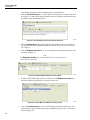
Test element properties consist of multiple pages, described below.
2. Click the General setup tab. A screen opens, allowing entry of a name for the test.
See Figure 4-2. In the space below the name, enter the procedures and instructions to
be followed when conducting the test.
Figure 4-2. User-Definable Parts of the General Setup Tab
git019.bmp
3. Click the Apply when tab to assign report levels, standards, and service events to
test elements. For more information about this feature, see the Ansur Test Executive
User Manual.
4. Click the Expected results tab to view or change the measurement limits for tests,
as shown in Figure 4-3.
Note
The Expected results page is unavailable when test elements do not
return measurement data.
Figure 4-3. Expected Results Options for User Input
git020.bmp
5. To add or delete limits, right click one of the rows of the Expected results page
and select from the pop-up menu, as shown in Figure 4-4.
Figure 4-4. Pop-Up Menu for Adding or Deleting Limits
git021.bmp
6. Click the Custom setup tab to view and define the parameters used in tests. Test
elements have unique custom setups for the capabilities they provide. An example is
shown in Figure 4-5.
4-4
Index 2XL Test Templates
Using Index 2XL Test Elements
4
6. Click the Custom setup tab to view and define the parameters used in tests. Test
elements have unique custom setups for the capabilities they provide. An example is
shown in Figure 4-5.
Figure 4-5. Custom Setup Page for SpO2 Simulator Test Element
git022.bmp
7. If desired, deselect (uncheck) either or both of the Test Guide Settings
checkboxes to disable the Skip and NA button options.
8. The Test Guide Settings control whether certain test elements can be skipped
altogether or marked as Not Applicable (NA) while the tests run. The Skip and NA
buttons are enabled by default. If a setting is enabled, the corresponding Skip or NA
button is available on the toolbar.
Using Index 2XL Test Elements
The test elements contained in the Index 2XL Plug-In are designed to test specific
functional elements of a pulse oximeter. Tables 4-1 through 4-5 list the parameters that
can be customized for each test element and the measurement data they provide.
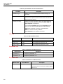
SpO2 Simulation Test
Table 4-1. SpO2 Simulation Test Measurements
Measurement
Unit of Measure
Description
SpO2 level
%
Percentage of Oxygen in Oxygenated Blood.
Beats per minute
BPM
Pulse Rate.
4-5
Ansur Index 2XL
Users Manual
Table 4-2. SpO2 Simulation Test Custom Parameters
Parameter
Description
Simulation Type
Allows you to choose between Optical and Electrical type of
simulation.
Oximeter Details
Allows you to set the Oximeter make name, view the custom RCurve, and an option to send the custom R-Curve to Index 2XL
before performing the test.
Simulation Settings
Allows you to set the simulation settings from the dropdown list.
For each simulation settings, the parameters SpO2, BPM, and
Pulse amplitude are predefined.
You can select Customize option from the dropdown list and
enter your own values for SpO2, BPM, and Pulse amplitude.
SpO2 is the percentage of oxygen in oxygenated blood.
BPM is the number of Pulses per Minute.
Pulse Amplitude is the amplitude of the Pulse.
LED Test
Table 4-3. LED Test Measurements
Measurement
Unit of Measure
Description
LEDs – R
Volts
The voltage drop across LED - R.
LEDs – IR
Volts
The voltage drop across LED - IR.
LEDs – PHTO
Volts
The voltage drop across LED - PHTO.
Photodiode Test
Table 4-4. Photodiode Test Measurements
Measurement
Description
Photodiode - R
Response of photodiode – R.
Photodiode - IR
Response of photodiode – IR.
Resistance Test
Table 4-5. Resistance Test Measurements
Measurement
Pin X to Pin Y
Unit of Measure
kilohms
Description
Resistance between two wires X and Y.
Note: Where X and Y are the pin numbers ranging
from 1 to 13.
4-6