1
SERIES IP501 INDUSTRIAL I/O PACK
EIA/TIA-422B SERIAL COMMUNICATION MODULE
___________________________________________________________________________________________
The information contained in this manual is subject to change
without notice. Acromag, Inc. makes no warranty of any kind with
regard to this material, including, but not limited to, the implied
warranties of merchantability and fitness for a particular purpose.
Further, Acromag, Inc. assumes no responsibility for any errors that
may appear in this manual and makes no commitment to update, or
keep current, the information contained in this manual. No part of
this manual may be copied or reproduced in any form, without the
prior written consent of Acromag, Inc.
Table of Contents
3.0
4.0
5.0
6.0
It is very important for the user to consider the possible adverse
effects of power, wiring, component, sensor, or software failures in
designing any type of control or monitoring system. This is
especially important where economic property loss or human life is
involved. It is important that the user employ satisfactory overall
system design. It is agreed between the Buyer and Acromag, that
this is the Buyer's responsibility.
Page
1.0 GENERAL INFORMATION............................. 2
2.0
IMPORTANT SAFETY CONSIDERATIONS
KEY IP501 FEATURES.................................................... 2
INDUSTRIAL I/O PACK INTERFACE FEATURES.......... 3
SIGNAL INTERFACE PRODUCTS.................................. 3
INDUSTRIAL I/O PACK SOFTWARE LIBRARY.............. 3
PREPARATION FOR USE................................................ 3
UNPACKING AND INSPECTION..................................... 3
CARD CAGE CONSIDERATIONS................................... 4
BOARD CONFIGURATION.............................................. 4
CONNECTORS................................................................. 4
IP Field I/O Connector (P2)............................................ 4
Noise and Grounding Considerations............................. 5
IP Logic Interface Connector (P1).................................. 5
PROGRAMMING INFORMATION.................................... 6
ADDRESS MAPS.............................................................. 6
IP Communication & Configuration Registers................ 8
IP Identification PROM................................................... 14
THE EFFECT OF RESET................................................. 15
IP501 PROGRAMMING.................................................... 15
FIFO Polled Mode.......................................................... 16
FIFO Interrupt Mode.......................................................16
Loopback Mode Operation............................................. 17
Interrupt Generation....................................................... 17
Software Flow Control……………………………………. 17
Hardware Flow Control…………………………………… 18
Programming Example...................................................18
THEORY OF OPERATION............................................... 19
EIA/TIA-422B SERIAL INTERFACE................................. 19
IP501 OPERATION........................................................... 20
LOGIC/POWER INTERFACE........................................... 21
SERVICE AND REPAIR.................................................... 21
SERVICE AND REPAIR ASSISTANCE........................... 21
PRELIMINARY SERVICE PROCEDURE......................... 21
SPECIFICATIONS............................................................. 21
GENERAL SPECIFICATIONS.......................................... 21
EIA/TIA-422B PORTS....................................................... 22
DRIVERS/RECEIVERS..................................................... 22
INDUSTRIAL I/O PACK COMPLIANCE........................... 22
APPENDIX.........................................................................23
CABLE: MODEL 5025-550. & 5025-551........................... 23
CABLE: MODEL 5029-943................................................ 23
TERMINATION PANEL: MODEL 5025-552..................... 23
TRANSITION MODULE: MODEL TRANS-GP................. 24
DRAWINGS
Page
4501-434 IP MECHANICAL ASSEMBLY......................... 25
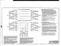
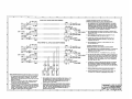
4501-552 IP501 COMMUNICATION CONNECTIONS... 25
4501-554 IP501 INTERFACE DIAGRAM........................ 26
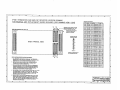
4501-555 IP501 TERM/BIAS RESISTOR LOCATION.... 27
4501-553 IP501 BLOCK DIAGRAM................................. 28
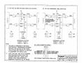
4501-570 RS-422 INTERFACE LEVELS......................... 29
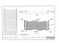
4501-462 CABLE 5025-550 (NON-SHIELDED).............. 30
4501-463 CABLE 5025-551 (SHIELDED)........................ 30
4501-464 TERMINATION PANEL 5025-552................... 31
4501-465 TRANSITION MODULE TRANS-GP............... 31
-2-
1.0 GENERAL INFORMATION
The Industrial I/O Pack (IP) Series IP501 module provides four
EIA/TIA-422B serial communication ports for interfacing to the
VMEbus or ISAbus, according to your carrier board. For half-duplex
EIA-485 applications, the model IP502 is recommended, but the
model IP501 can be used to implement an EIA-485 interface
operating in full-duplex. Full-duplex data paths for Transmit (Tx),
Receive (Rx), and the Request-to-Send (RTS) and Clear-to-Send
(CTS) handshake lines are included. Four units may be mounted on
a carrier board to provide up to 16 asynchronous serial ports per
system slot.
The transmit and receive paths of each channel on IP501-16
units include generous 16-byte FIFO buffers to minimize CPU
interaction. Model IP501-64 units utilize 64-byte FIFO buffers and
include software flow controls. Full-duplex EIA/TIA-422B and
EIA-485 DB-9 signal support for the common RTS and CTS
handshake lines is included. Character size, stop bits, parity, and
baud rate are software configurable. Prioritized interrupt generation
is also supported for transmit, receive, line-status, and data set
conditions. The IP501 utilizes state of the art Surface-Mounted
Technology (SMT) to achieve its wide functionality and is an ideal
choice for a wide range of industrial communication interface
applications that require a highly reliable, high-performance interface
at a low cost. For isolated interface requirements, refer to the
Acromag Model IP511.
KEY IP501 FEATURES
High Density - Provides programmable control of four EIA/TIA422B serial ports. Four units mounted on a carrier board
provide 16 serial channels in a single VMEbus or ISAbus
(PC/AT) system slot.
• Large FIFO Buffers - The transmit and receive channels of
each serial port provide generous 16-character (IP501-16), or
64-character (IP501-64) data buffering. This gives the host
CPU additional time to process other applications and reduces
CPU interactions and interrupts.
• Programmable Character Size - Each serial port is software
programmable for 5, 6, 7, or 8 bit character sizes.
• Programmable Stop Bits - Each serial port allows 1, 1-1/2, or
2 stop-bits to be added to, or deleted from, the serial data
stream.
• Programmable Parity Generation & Detection - Even, Odd,
or No Parity generation and detection is supported.
• Line-Break Generation & Detection - provision for sending
and detecting the line break character is provided.
• False Start Bit Detection - Prevents the receiver from
assembling false data characters due to low-going noise spikes
on the RxD input line.
•