1
Chapter3. Getting Start
Before Getting Started
Administrators should read this part of the manual carefully, especially during installation. Please
verify that all the items in the Package Checklist are presented. Before initial installation and
configuration the device, you will also need a PC or notebook PC within Ethernet port.
Step 1: Connect the power source
Please find a suitable AC-DC power adapter which it is a part of the packaging. The
converter device is powered by a single 9VDC (inner positive/outer negative) power
source with 500mA of current. The adapter of AC input power is autosensing design from
110∼240 voltage. The DC power jack at the left side of the ZigBee device and put
the adapter into the socket. If the power is properly supplied, the “PWR” LED will be
on.
Step 2: Check the power status of the device
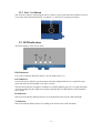
When power is connected and users can verify the LED indicator of “PWR” on the top
panel. If the power is properly supplied, the “PWR” LED indicator will be on that if the
power input fails, LED indicators will not be light up.
Step 3: Check the status of the device after connecting the power
When power is properly worked and the next step is to pairing with “ZigBee Coordinator”
device. To verify the LED indicator of “Pair”, if the pair is successful that the “Pair” LED
indicator will be blinking every three seconds.
3.1 Hardware Installation
3.1.1 DIN-Rail Mounting
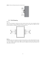
The aluminum DIN-Rail attachment plate is included in the package. If you need to reattach the
DIN-Rail attachment plate to the converter, make sure the stiff metal spring is situated towards the
top, as shown in the figures below.
The DIN-Rail attachment plate should already be attached to the back panel of the converter
device. If you need to reattach the plate, make sure the metal spring is situated towards the top, as
shown in the figures below.
STEP 1: Insert the top of the DIN-Rail into the slot just below the metal spring.
13