1
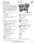
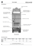
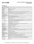
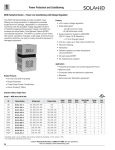
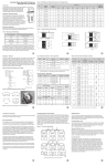
3
Power Supplies
SDN-P DIN Rail Series
The SDN DIN Rail power supplies provide industry leading
performance. Sag Immunity, transient suppression and noise
tolerant, the SDN series ensures compatibility in demanding
applications. Power factor correction to meet European
directives, hazardous location approvals and optional
redundant accessories allow the SDN series to be used in
a wide variety of applications. Wide operation temperature
range, high tolerance to shock and vibration and reliable
design make the SDN series the preferred choice of users.
UL 60950
EMC and
E137632
E61379
UL
508 Listed
E137632
Low Volt.
E234790
IND. CONT. EQ. CUL/CSA-C22.2 Directive
E61379
No. 234-M90
Applications
• Industrial/Machine Control
• Process Control
• Conveying Equipment
• Material Handling
• Vending Machines
• Packaging Equipment
• DeviceNetTM
• Amusement Park Equipment
• Semiconductor Fabrication Equipment
Features
• Power Factor Correction (per EN61000-3-2)
• Auto Select 115/230 Vac, 50/60 Hz Input
• Improved metal mounting clip
Certifications and Compliances *
All Models
Listed, Ind. Control Equipment, E61379
•
-UL 508, CSA C22.2 No. 107.1
•
UL Recognized Component, ITE, E137632
UL 60950
E137632
-UL
60950-1/CSA
C22.2 No. 60950-1, 2nd Edition
CUL/CSA-C22.2
No. 234-M90
•
UL Recognized Component, Haz. Loc.,
UL 60950
E137632
E234790
CUL/CSA-C22.2
UL 508 Listed
IND. CONT. EQ.
E61379
-ISA 12.12.01, CSA C22.2 No. 213
-Class I, Division 2, Groups A, B, C, D
•
- Low Voltage Directive
No. 234-M90
-IEC/EN60950-1, 2nd Edition
• Sag Immunity: SEMI F47
• RoHS Compliant
• DC OK Signal
Models SDN 2.5-24-100P, SDN 4-24-100LP
• Adjustable Voltage
• Class 2 per UL 1310, CSA C22.2 No. 223
• Parallel Capability standard on all units
• Industrial grade design
Related Products
- -10°C to 60°C operation without derating. Indefinite short
circuit, overvoltage and overtemperature protection.
• SDP™ Series
- Powers high inrush loads without shutdown or foldback
• SCL Series
- Rugged metal case and DIN connector
• SDU UPS
• SCP Series
• Narrow width on rail for space critical applications
• User-friendly front panel
- Large, rugged, accessible, multiple connection screw
terminations
- Easy installation
• 12 Vdc and 48 Vdc single phase models available
• Highly efficient >90% switching technology
• High MTBF and reliability
Accessories
• Chassis Mount Bracket (SDN-PMBRK2)
* Refer to user manual for installation requirements when used in hazardous locations.
Phone: 800.894.0412 - Fax: 888.723.4773 - Web: www.clrwtr.com - Email: [email protected]
3
Power Supplies
SDN-P Specifications (Single Phase), 24 Vdc Output
Catalog Number
Description
SDN 2.5-24-100P
SDN 4-24-100LP
SDN 5-24-100P
SDN 10-24-100P
Input
115/230 Vac, Auto select
Nominal Voltage
-AC Range
85-264 Vac
-DC Range 1
90 - 375 Vdc
85-132/176-264 Vac
210 - 375 Vdc
47 - 63 Hz
-Frequency
Nominal Current 2
1.3 / 0.7 A
-Inrush current max.
typ. < 25 A
2.1 / 1.0 A
Efficiency (Losses 3)
> 87.5% typ. (8.6 W)
2.2 / 1.0 A
5 / 2 A typ.
> 88% typ. (16.4 W)
> 88% typ. (32.7 W)
typ. < 20 A
> 88% typ. (13.1 W)
typ. < 40 A
Units Fulfill EN61000-3-2
Power Factor Correction
Output
24 Vdc
(22.5 - 28.5 Vdc adj.)
Nominal Voltage
24 Vdc
(22.5 - 28.5 Vdc adj.)
< ±2% overall (combination Line, load, time and temperature related changes)
-Tolerance
-Ripple
24 Vdc
(22.5 - 28.5 Vdc adj.)
< 50 mVpp
4
Overvoltage Protection
Nominal Current
< 33 Vdc
< 27 Vdc
2.5 A (60 W)
3.8 A (92 W)
< 33 Vdc
5 A (120 W)
10 A (240 W)
Fold Forward (Current rises, voltage drops to maintain constant power during overload up to max peak current)
-Current Limit
> 20 ms @ full load
Holdup Time 5
Single or Parallel use is selectable via Front Panel Switch
(SDN 2.5, 4 should not be used in parallel as Class 2 rating would be violated.)
Parallel Operation
General
EMC:
-Emissions
EN61000-6-3, -4; Class B EN55011, EN55022 Radiated and Conducted including Annex A. EN61000-3-2
EN61000-6-1, -2; EN61000-4-2 Level 4, EN61000-4-3 Level 3; EN61000-4-6 Level 3; EN61000-4-4 Level 4 input and Level 3 output;
EN61000-4-5 Isolation Class 4, EN61000-4-11;
-Immunity
Storage: -25oC...+85oC Operation. -10°-60oC full power with operation to 70°C possible with a linear derating to half power from 60oC to 70oC
(Convection cooling, no forced air required).
Operation up to 50% load permissible with sideways or front side up mounting orientation.
Temperature
The relative humidity is < 90% RH, noncondensing; IEC 68-2-2, 68-2-3.
Humidity
> 820,000 hours MTBF:
> 640,000 hours
> 600,000 hours
Bellcore Issue 6 Method 1 Case 3 @ 40oC
- Standard
5 year limited warranty
Warranty
Protected against continuous short-circuit, overload, open-circuit. Protection Class 1 (IEC536),
degree of protection IP20 (IEC 529) Safe low voltage: SELV (acc. EN60950)
General Protection/Safety
Green LED and DC OK signal (N.O. Solid State Contact rated 200 mA / 60 Vdc)
Status Indicators
Installation
Fusing
-Input
Internally fused. External 10 A slow acting fusing for the input is recommended to protect input wiring.
Outputs are capable of providing high currents for short periods of time for inductive load startup or switching. Fusing may be required for wire/
loads if 2x Nominal O/P current rating cannot be tolerated. Continuous current overload allows for reliable fuse tripping.
-Output
Simple snap-on system for DIN Rail TS35/7.5 or TS35/15 or chassis-mounted (optional screw mounting set SDN-PMBRK2 required).
Mounting
Input: IP20-rated screw terminals, connector size range: 16-10 AWG (1.5-6 mm2) for solid conductors. 16-12 AWG (0.5-4 mm2) for
flexible conductors. Output: Two connectors per output, connector size range: 16-10 AWG (1.5 - 6 mm2) for solid conductors.
Connections
Fully enclosed metal housing with fine ventilation grid to keep out small parts.
Case
25 mm above and below,
25 mm left and right, 10 mm in front
-Free Space
H x W x D inches (mm)
Weight lbs (kg)
25 mm above and below, 25 mm
left and right,
15 mm in front
70 mm above and below, 25 mm
left and right,
15 mm in front
4.88. x 1.97 x 4.55
(124.0 x 50.0 x 116.0)
4.88 x 2.56 x 4.55
(124.0 x 65.0 x 116.0)
4.88 x 3.26 x 4.55
(124.0 x 83.0 x 116.0)
1.6 (.73)
2.4 (1.10)
3.3 (1.50)
1. Not UL listed for DC input.
2. Input current ratings are conservatively specified with low input, worst case
efficiency and power factor.
3. Losses are heat dissipation in watts at full load, nominal input line.
4. Ripple/noise is stated as typical values when measured with a 20 MHz,
bandwidth scope and 50 Ohm resistor.
5. Full load, 100 Vac Input @ Tamb = +25°C
Phone: 800.894.0412 - Fax: 888.723.4773 - Web: www.clrwtr.com - Email: [email protected]
3
Power Supplies
SDN-P Specifications (Single Phase), 12 Vdc and 48 Vdc Output
Description
Catalog Number
SDN 9-12-100P
SDN 5-48-100P
SDN 16-12-100P
Input
115/230 Vac auto select
Nominal Voltage
-AC Range
85-132/176-264 Vac; 210 - 375 Vdc
-DC Range 1
210 - 375 Vdc
47 - 63 Hz
-Frequency
Nominal Current
2
2.0 A / 1.5 A
-Inrush current max.
Typ. < 20 A
Efficiency (Losses 3)
> 84% typ. (17.28 W)
4 A / 2.3 A
3.3 A / 1.7 A
typ. < 40 A
> 88% typ. (28.8 W)
> 84% typ. (30.72 W)
Units fulfill EN61000-3-2
Power Factor Correction
Output
Nominal Voltage
12 V (11.6-15.2 Vdc Adj.)
48 V (35.8 - 52 Vdc Adj.)
12 V (11.6-14.2 Vdc Adj.)
< ±2 % overall (combination Line, load, time and temperature related changes)
Tolerance
-Line Regulation
< 0.5%
-Load Regulation
< 0.5%
< 1%
-Time & Temp. Drift
< 50 mVpp
Ripple 4
Overvoltage Protection
Nominal Current
-Current Limit
< 16 Vdc with auto-recovery
< 60 Vdc with auto-recovery
< 16 Vdc with auto-recovery
9 A (108 W)
5 A (240 W)
16 A (192 W)
110% of nominal - Fold Forward (Current rises, voltage drops to maintain constant power during overload up to max peak current)
>20 ms @ full load
Holdup Time 5
Supplies will not be damaged with parallel operation
Parallel Operation
Power Back Immunity
16 Vdc
60 Vdc
16 Vdc
General
EN61000-6-3, EN61204-3, EN55022 Class B, EN61000-3-2, EN61000-3-3
EMC: -Emissions
-Immunity
Temperature
EN61000-6-2, EN61204-3, EN55024, IEC61000-4-2, IEC61000-4-3, IEC61000-4-4, IEC61000-4-5, IEC61000-4-6, IEC61000-4-8, IEC61000-4-11
Storage: -25 to +85oC, Operation -10 to +60oC full power; with linear derating to half power from 60 to 70oC
(Convection cooling, no forced air required). Operation up to 50% load permissible with sideways or front side up mounting orientation.
< 90% RH, non-condensing; IEC 68-2-2, 68-2-3
Humidity
>500,000 hrs MTBF:
Telcordia/Bellcore, Issue Case 3 @ 25oC - Standard
5 year limited warranty
Warranty
General Protection/Safety
Protected against continuous short -circuit, continuous overload, continuous open circuit. Protection Class 1 (IEC536),
Degree of Protection IP20 (IEC 529) Safe low voltage: SELV (acc. EN60950)
Status Indicators (Visual)
Green LED on when Vout > 75% (with ± 5% tolerance) of nominal output voltage
Status Indicators (Relay)
Normally Open solid state relay - signal active when Vout >70% of nominal output voltage (rated up to 200 mA, 60 Vdc)
Installation
Fusing
-Input
-Output
Mounting
Connections
Internally fused
Outputs are capable of providing high currents for short periods of time for inductive load startup or switching. Fusing may be required if
Nominal O/P current rating cannot be tolerated. Continuous current overload allows for reliable fuse tripping.
Simple snap-on to DIN TS35/7.5 or TS35/15 rail system. Unit should handle normal shock and vibration of industrial use
and transportation without falling off the rail.
Input: Screw terminals, connector size range: 16-10 AWG (1.5-6mm2) for solid conductors.
Output: Two terminals per output, connector size range: 16-10 AWG (1.5-6mm2) for solid conductors.
Fully enclosed metal housing with fine ventilation grid to keep out small parts.
Case
70 mm above and below, 25 mm left and right, 15mm in front
-Free Space
H x W x D inches (mm)
Weight lbs (kg)
4.88 × 2.56 × 4.55 (124.0 x 65.0 × 116.0)
4.88 × 3.23 × 4.55 (124.0 × 83.0 × 116.0)
2.4 (1.10)
3.3 (1.50)
1. Not UL listed for DC input.
2. Input current ratings are conservatively specified with low input, worst case
efficiency and power factor.
3. Losses are heat dissipation in watts at full load, nominal input line.
4. Ripple/noise is stated as typical values when measured with a 20 MHz,
bandwidth scope and 50 Ohm resistor.
5. Full load, 100 Vac Input @ Tamb = +25°C
Phone: 800.894.0412 - Fax: 888.723.4773 - Web: www.clrwtr.com - Email: [email protected]
3
Power Supplies
SDN-P Series Dimensions
D
W
+ +
-
-
OK
24 VDC / 2.5 A
OK
NEC Class 2
Power Supply
24-28 V
Single
Parallel
H
S O LA
Power Supply
SDN 2.5-24-100P
C
U
L
���� ���� ��
����
US LISTED
115/230 VAC 1.3-0.7 A 50/60 HZ
N
Catalog
Number
L
Dimensions - inches (mm)
H
W
D
12 Vdc
SDN 9-12-100P
4.88 (124.0)
2.56 (65.0)
4.55 (116.0)
SDN 16-12-100P
4.88 (124.0)
3.23 (83.0)
4.55 (116.0)
SDN 2.5-24-100P
4.88 (124.0)
1.97 (50.0)
4.55 (116.0)
SDN 4-24-100LP
4.88 (124.0)
2.56 (65.0)
4.55 (116.0)
SDN 5-24-100P
4.88 (124.0)
2.56 (65.0)
4.55 (116.0)
SDN 10-24-100P
4.88 (124.0)
3.26 (83.0)
4.55 (116.0)
3.23 (83.0)
4.55 (116.0)
24 Vdc
48 Vdc
SDN 5-48-100P
4.88 (124.0)
Phone: 800.894.0412 - Fax: 888.723.4773 - Web: www.clrwtr.com - Email: [email protected]
3
Power Supplies
SDN-P Series Mounting
DIN Rail Mounting
Snap on the DIN Rail:
1. Tilt unit slightly backwards
2. Put it onto the DIN Rail
3. Push downwards until stopped
4. Push at the lower front edge to lock
5. Shake the unit slightly to ensure that the retainer
has locked
Alternative Panel Mount: Using the optional SDN-PMBRK2
accessory, the unit can be screw mounted to a panel.
Detachment from DIN Rail:
Chassis Mounting
Dimensions - in. (mm)
Instead of snapping a SolaHD SDN™ unit on the DIN Rail,
you can also attach it using the screw mounting set
SDN-PMBRK2. This set consists of two metal brackets, which replace the
existing two aluminum profiles.
1.59
(40.4)
.70 (17.8)
.43 (10.9)
.60 (15.2)
.23 (5.8)
.51 (13.0)
.18
.86 (4.6)
(21.8)
2.16 (54.9)
.60
(15.2)
1.30
(33.0)
1.80
(45.7)
.35
(8.9)
.08 (2.0)
.23 (5.8)
.40
(10.2)
.25 (6.4)
.26 (6.6)
.52 (13.2)
.52 (13.2)
Phone: 800.894.0412 - Fax: 888.723.4773 - Web: www.clrwtr.com - Email: [email protected]