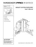
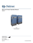
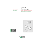
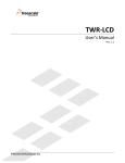
1
US3 USER MANUAL 2.2 PLEASE TAKE TIME TO READ THIS USER GUIDE BEFORE INSTALLING YOUR SEAL SCRAMMER © Ace Aquatec Ltd. 2014. The Company reserves the right to alter without notice the specification, design, price or conditions of supply of any product or service. Ace Aquatec recognises and acknowledges all Trade Marks. 1 INDEX 1. BEFORE YOU START 4 1.1. Check the Contents 4 1.2. Contact Information 5 1.3. About this Guide: Colour Code 1.4. Equipment Warning 5 1.5 Environmental Notice 5 1.6 Safety Notice 5 6 2. PLANNING INSTALLATION 6 2.1 Number of underwater bodies 6 2.2 Number of Motion Trigger Devices 7 2.3 Positioning Equipment: 8 3. CONNECTING & INSTALLING EQUIPMENT 9 3.1 Unpacking the Equipment 9 3.2 Fixing Harsh Environment to Cage 9 3.3. Connecting the Underwater Body 10 3.4. Connecting the Control Box 3.5 Connecting Power Supply 3.5.1 External battery/ies 3.5.2 Mains 11 12 12 14 3.6 Deploying Trigger Devices 2 14 3.6.1 Hanging motion triggers 3.6.2 Hanging Sonar triggers 4. GETTING STARTED 15 18 19 4.1. Understanding the Display 4.2. Standby Screen 19 20 4.2.1 System Status 20 4.2.2 Power Readings 4.3. Main menu 21 22 4.3.1 Selecting a Mode 23 4.3.2 Selecting a Rate Value 24 4.3.3 Setting a Scram Rate 25 4.3.4 Alert Faults 26 4.3.5 Trigger Data 27 4.3.6 Stats Menu 27 4.3.7 Sensor Data 28 4.3.8 Time Data 28 4.4. Devices 29 4.4.1 Underwater Body Settings 29 4.4.2 General Purpose Input/Output 30 4.4.3 System Settings 5 Software Updates 31 6 Maintenance 32 7 Storage 34 8 UK and International 35 8 Additional Documents 36 3 30 1. BEFORE YOU START 1.1. Check the Contents 1 x Under Water Body 1 x Under Water Cable 1 x Harsh Environment Shell 1 x Top control box (pre-attached) 1 x AC connector 1 x User Guide TDX Trigger Device(s) - Silent Scrammers only 4 1.2. Contact Information For advice or technical assistance contact Ace Aquatec: EMAIL: [email protected] For returns, repairs, calibration or annual servicing send to: ACE AQUATEC LTD, C/O NEPTUNE SONAR LTD. KELK LAKE, KELK, DRIFFIELD, YORKSHIRE, YO25 8HG 1.3. About this Guide: Colour Code Text in green is ADVISORY. Text in red indicates MANDATORY. If unheeded, may result in sub-optimal performance or DAMAGE. 1.4. Equipment Warning Never connect ANY part of a 1st generation Ace Aquatec scrammer to any part of a 2nd or 3rd generation system. (Including cables and triggers). SEVERE DAMAGE will result and neither unit will function without repair. 1.5. Environmental Note Underwater noise pollutes the environment and disturbs 5 dolphins and whales. By not making sounds unnecessarily the US3 balances the welfare of the fish against the needs of the environment. The acoustic output of the scrammer is designed to be inaudible to fish thereby avoiding stress. 1.6. Safety First The US3 produces high levels of under-water noise. The hearing of divers will not be damaged by accidental exposure to this level but the sudden sound might startle the diver. If divers are operating near the scrammer it MUST BE SWITCHED TO MUTE MODE. 2. PLANNING INSTALLATION 2.1 Number of underwater bodies The US3 has a nominal deterrence range of 50 METRES (harbour & grey seals). Site your scrammer in a centralised position to the area that you wish to protect. 6 2.2 Number of Motion Trigger Devices The number of Trigger Devices depends upon the size and shape of your pens: The more Triggers the higher the probability an excited fish will contact and initiate a scram. SQUARE PEN RECOMMENDATIONS: PEN SIZE TRIGGERS PER PEN 12m / 15m steel cages 2 24m steel cages 4 CIRCULAR PEN RECOMMENDATIONS: PEN SIZE TRIGGERS PER PEN 70m polar 2 Up to 100m polar 3 100m + 4+ 7 2.3 Positioning Equipment: UNDERWATER BODY MUST BE IMMERSED TO A DEPTH GREATER THAN 5M UNDERWATER BODY Suspended: >1 metre below the deepest point of the growing net >2 meters above the sea bed TRIGGERS Suspended: Clear of underwater obstructions (the nets themselves, adaptive feeders, lights etc.) Preferably below the normal feeding zone of the Preferably midwater. fish. Within 50m of scrammer. SURFACE CAGE TRIGGERS SCRAMMER 8 3. INSTALLING EQUIPMENT 3.1 Unpacking the Equipment Harsh Environment Shell Underwater Body Top Control Box Cable 3.2 Fixing Harsh Environment to Cage Uprights should be lashed to the handrail using rope. The base should be lashed to the walkway. 9 3.3. Connecting the Underwater Body OPTIONAL A sinker plate has been attached to the underwater body with 4 nylon screws to increase its weight. This can be removed if so desired. Sinker plates need replacing every 2-3 years. STEP 1: A rope should be tied through the top neck/cage of the underwater body (or a shackle attached to the central strong point) and the other end attached to a suitable anchor point in order to take the weight of the US3. Ensure rope does not make contact with the black transducer. STEP 2: Connect the male end of the black cable to the female socket on the underwater body. (Ensure pins are properly aligned before pushing. While holding the cable, push connector until there is no gap and screw the red knurled cap until hand-tight) 10 STEP 3: Ensure the cable exits through the top rather than the side of the scrammer’s cage. STEP 4: Deploy to the correct depth (see 2.3) ensuring cable is slack and weight is taken by the rope. Never power up the scrammer unless the transducer is submerged in water. Testing in air will damage the hydrophone! 3.4. Connecting the Control Box RADIO / EXT. BATTERIES UNDERWATER AC POWER BODY 11 STEP 1: Plug the female end of the black underwater cable into the male socket beneath the surface electronics. Ensure there is no gap and the red cap is screwed finger tight. STEP 2: Additional tie-wraps (or rope) should be used to secure the cable to the right hand Harsh Environment uprights ensuring there is some slack. 3.5. Connecting Power Sources The US3 runs from AC and/or batteries. If the power source is weak the scrammer will switch itself off as the internal battery discharges. It will eventually enter MUTE mode until an adequate external source has been connected. 3.5.1. Batteries The US3 takes 1 or 2 external 12V, 75, 85, or 100 AHr batteries (L. 302cm x W. 172cm x H. 225cm) 12 2 batteries are recommended if you are not connecting to AC. Rotate a 3rd battery for most efficient use. STEP 1: Remove aluminium lid. Locate battery cable. Ensure cable is fed through the base hole to the junction box. STEP 2: Connect battery cable into the left battery port on the control box. Cable tie cable to left harsh environment uprights leaving some slack. STEP 3: Insert 1, or 2, 12 volt battery/ies with terminals facing inwards. Attach red leads to “+“ (P) and brown (black) leads to “-” (N). STEP 4: Once battery leads are connected replace aluminium lid and lock with rubber clips (if only one battery is used, cable-tie the battery cables to the central anchor point). 13 3.5.2. Connecting Mains AC If AC is connected the US3 automatically recharges the external battery/ies and will switch to battery automatically if AC is lost. An Amphenol ecomate 4 pin connector has been supplied for connecting to an AC power source (90 to 264 V) The 4 connections are: 2 — Live, 1 — Neutral, E — (triangle of 3 horizontal lines arranged as an inverted triangle) Earth, 3 — Not connected. (US3 requires 1amp—75 watts) WARNING! Never attempt to connect AC cable to battery connector input on the top box! Never unscrew front panel of control while connected. Opening control box may invalidate your warranty. 3.6 Deploying the Trigger Devices REMOVE MAGNETS BEFORE USE TO SWITCH ON. REPLACE TO SWITCH OFF. FRAGILE! HANDLE CAREFULLY! RECORD WHICH DEVICE IS IN WHICH PEN. LEAVE THE MAGNETS IN A SAFE PLACE ASHORE. 14 3.6.1 Hanging Suggestions for Fish Motion Detector Triggers Rope Triggers Light Line (Below feeding line) 3-5m Below surface Depth: Not critical. However, potential effects of storms and tides should be considered to prevent false alarms (from contact with growing nets or any other underwater obstacle). Varying threshold: If the growing nets do hit the device regularly then the system de-sensitises and fish panicking may not be detected. 15 A site diagram will have been provided by Ace Aquatec showing the position of your US3 deterrents (yellow dots, with a blue circle for coverage), your grids (black squares) and you cages (green circles). Deployment of fish motion detector triggers will have been marked in red as above. 16 Fish Motion Triggers have a serial code on the top which matches the cage number where you intend to install them e.g all triggers with the code 001 should be hung in cage 1, all 002s should be placed in cage 2 and so on, as illustrated below. Triggers should be hung as indicated in the diagrams Hang triggers with light line through the trigger’s top holes See 4.4.1 to set US3s to listen to particular cages Add the provided shackles to the top of triggers for tidal sites. Once triggers are set up in the cages proceed to set which US3 top box should listen to which set of triggers. See 4.1.4 for setting Us3 top boxes to listen to particular triggers. 17 3.6.2 Hanging Suggestions for Sonar Triggers SONAR triggers should be fixed to the edge of the cage facing the direction of seal approaches. Optimal depth is 1-2 metres but this will depend on the severity of waves. One trigger should be deployed on each of the inner cages of the grid. Two triggers should be deployed on the cages at either end of the grid. 18 4. GETTING STARTED 4.1. UNDERSTANDING THE DISPLAY TOUCH PAD: The cursor on the display is moved by pressing the up, down, left and right arrows on the touch pad. The central ENTER button selects an option. WARNING BEACON: to attract attention in the event of low batteries or a fault. USER DISPLAY: will light up as soon as the user hits a key on the key pad. WELCOME SCREEN ENTER THE UNLOCK CODE SUPPLIED BY EMAIL! Model, software version, serial number US3 Version 4.2 S/N 24624 19 4.2 STANDBY SCREEN Power readings (left) & System Status (right). System OK Mute BatA 120 V TE 125 BatB None TR 503 Mains On TT 301 4.2.1 System Status (right) Triggered events: TE 125 valid trigger events The system is either in since last reset. These Mute mode (making no are registered from ex- noise) or Scram mode ternally connected devic- (making noise). es, such as motion detector triggers or sonar triggers. Triggered scrams:TR 503 scrams made by Timed: TT. 301 timed the scrammer in re- scrams since reset. sponse to TE’s These are determined by the rate and do not include triggered scrams. 20 4.2.2 Power Readings (left) These occupy the left hand side of the screen and should be checked regularly. “SYSTEM OK” lets you know everything is operating correctly. Alerts such as low batteries or communications failure will display here. System OK Mute BatA 120 V TE 0 BatB None TR 0 Mains On EXT A + EXT B are the external batteries attached to the control box. Here, Battery A is reading 12.0V. No 2nd battery is attached (NONE). TT 0 When Mains AC is connected the sta- Batteries should be changed when readings fall below 12 V. At 11V “BAD” appears indicating a dead battery (attention light will be lit in the event of “BAD” appearing (see 4.8)) tus reads “ON”. When AC is not connected it reads “OFF”. Press any key to go to the “MAIN MENU“. 21 4.3. MAIN MENU On the left you find a real time clock and the product’s serial number. The right has settings that can be toggled by the user. Main Menu Mute 11:05:18 Rate 2 Stats S/N 24483 Devices 72 4.3.1 SELECTING A MODE ONLY SCRAM WITH U/W BODY IN WATER! The user can scroll through two functions on the first line. Option 1: MUTE - effectively means the scrammer is OFF. It is listening but not making noise. Option 2: SCRAM—the scrammer is operational and will make a noise, either when triggered or on a timed basis depending on the rate figure selected. 22 1. Move the triangle cursor to the MUTE function using the and arrow keys. Main Menu Mute 11:05:18 Rate 2 Stats S/N 24483 Devices 3) Press Main Menu Mute 11:05:18 Rate 2 Stats S/N 24483 Devices 2. Press ENTER 72 or to scroll to next option (SCRAM or MUTE). 72 to highlight the option. Main Menu Scram 11:05:18 Rate 2 Stats S/N 24483 Devices 72 Main Menu Scram 11:05:18 Rate 2 Stats option you require, S/N 24483 Devices press ENTER. 4) When you reach the 72 Note: Repeat steps to return the scrammer to MUTE. 23 If SCRAM is selected a safety screen appears giving the user 10 seconds to abort. If Scram is not required pressing any key will cancel the request. Going into scram mode in 10 seconds U/W MUST BE IN THE WATER Any key to abort 4.3.2 SELECTING A RATE VALUE SCRAMMER ONLY: Set a high rate if you are experiencing seal morts to push predators away. Once morts are down, reduce to a moderate or low rate to avoid habituation. If you have low to no seal morts keep at a low rate. WITH TRIGGERS: Triggers detect the presence of a predator and signal scrams. The rate should be set to “0” to create scrams only when a predator is near. This is recommended if you have no morts. You can also set a RATE above “0” when experiencing losses to push predators away. This can be reduced to “0” once predators’ behaviour has been changed. 24 4.3.3 SETTING THE SCRAM RATE The Rate refers to the number of TIMED scrams that the scrammer will make in any given hour (0-144 per hour). This rate is independent of ‘triggered scrams’. Main Menu Scram 11:05:18 Rate 2 Stats S/N 24483 Devices 1) Scroll down to RATE option using 72 arrows. 2) Press ENTER to enter rate value. Main Menu Scram 11:05:18 Rate 2 Stats S/N 24483 Devices 72 Main Menu Scram 11:05:18 Rate 2 Stats desired amount (0-144 S/N 24483 Devices per hour). 3) Use +/84 4) Press ENTER to select that value. to increase the rate to the Main Menu Scram 11:05:18 Rate 2 Stats S/N 24483 Devices 25 84 4.3.4 ALERT FAULTS A RED WARNING LIGHT will show if: 1. BATTERY IS LOW. The user receives an Error message. Check battery status on power settings. 2. THERE IS A FAULT: The “ERROR” code appears on the standby screen on the first line instead of “System ok”. Press ENTER to see the specific fault and solution. FAULT CODES: CABL – Check cable connections and "If damaged replace." BAT FAIL – The battery is dead. Replace battery. U/W / SCRAM FAILURE—A problem has arisen in the underwater body. Please “Service unit". CODE FAIL – If a fault code appears please contact Ace Aquatec for further instructions. If multiple errors have occurred the display will scroll through each error at 10 second intervals (or when a key is pressed). 10 seconds after the last error message the system reverts to the Normal screen. 26 4.3.5 TRIGGER DATA Stats stores information from external triggering devices, such as fish motion detector triggers or sonar triggers. Main Menu Scram 11:05:18 Rate 2 Stats S/N 24483 Devices 1) Scroll down to Stats option using 72 arrows. Main Menu Scram 11:05:18 Rate 2 Stats S/N 24483 Devices Stats Menu Sensor The time from which all 11:05:18 Time stats have been record- Last Start Reset ed. Scroll to reset and 13:35 26/06 Devices 2) Press ENTER to open stats menu. 4.3.6 Stats Menu 72 Current time. press Enter to begin stats recording from Scroll to Sensor and current time. press Enter for hits for Stats Menu Sensor 11:05:18 Time Last Start Reset 13:35 26/06 Devices each trigger number. Scroll to Time and press Enter for chronological records of hits. 27 4.3.7 Sensor Data Reading each line from left to right, each block represents a trigger, each number recorded represents the hits for that trigger. 25 3Devic 2 13 5 2 11 15 5 16 25 12 14 5 1 11 Trig 2 hits 3 Trig 1 hits 25 Trig 6 hits 2 Pressing any key returns to the stats Menu. 4.3.8 Time Data Press Enter to see stats by hour, day, month. Stats time By Hr 11:05:18 By Day 2 By Mo S/N 24483 S Devices 1 hr prev. hits 1 2 hrs prev. hits 4 Hour screen details total number of trigger hits detected by US3 in that hr. Top left is 1hr previously, bottom right 16 hrs. 28 1 4Devic 8 1 2 1 1 1 2 6 5 2 1 5 1 1 4.4 Devices The device menu allows core system settings to be changed. Device Menu U/W 11:05:18 GPIO 2 System S/N 24483 S Devices 4.4.1 Underwater Body Settings Scroll to U/W and press ENTER. The U/W menu allows the user to toggle acoustic output, test the unit, and adjust triggers heard. Device Menu Test Toggle to test and press 11:05:18 Sensors Enter to ensure scram- yyyyynyy2 mer is receiving an echo yynyyyyy483 S and responding. Press Enter to select. Toggle to Sensors and press Enter to select which triggers should be recorded. A summary is displayed. 29 4.4.2 General Purpose Input/Output Additional external devices can be connected to the US3 scrammer. The list of these connected devices can be found by clicking Enter on GPIO and selecting either Relays or Inputs, depending on the device attached. Device Menu U/W GPIO Menu Relays 11:05:18 GPIO 11:05:18 Inputs 2 System 2 System S/N 24483 S Devices S/N 24483 S Devices 4.4.3 System Settings Press ENTER to see System Menu where the real time clock can be set, internal battery charged and volume of scrams adjusted. Change each by pressing Enter and using the buttons to toggle settings. System Menu U/W System Menu Time 11:05:18 GPIO 11:05:18 Charge 2 System 2 Volume S/N 24483 S Devices S/N 24483 S Devices 30 5. Software Updates Updates for the scrammer can be downloaded from our website, supplied on disc, or added by our engineers. Ensure the top box and underwater body are connected, and that mains or batteries are supplying power. Insert the update cable into the utility connector port and the other end into your computer’s USB port. If the software has been added to your computer the programme should start running immediately. 31 6.MAINTENANCE Regular maintenance will prolong the life and effectiveness of your system. OCCASIONAL: 1) Check the underwater cable for abrasions. 2) Check the surface unit connectors to ensure they have not been damaged. REGULAR (DAILY) 1) Press the Test button to ensure the scrammer is reading “Echo” and is making a noise (scram mode). 2) Check the power settings. If BAT A/B reads under 120 (12.0 volts) then change the battery. If running from mains, ensure that AC reads “okay”. TEST 32 REGULAR: (ONCE A MONTH) 1) Put in MUTE mode and remove the underwater body from the water and pressure wash to remove any build up of organic material. 2) Clean battery terminals with a wire brush to avoid corrosion. Apply electrical grease to keep good connections. 3) Lift triggers to check each are working. You will hear them make a noise in the air when knocked (they have a time-out so will not make a noise immediately after being triggered). Clean. ANNUAL: Return the complete unit for servicing every year (or whenever your sites are fallow). 33 7. STORAGE The system should be fully charged before storing (use CHARGE setting, see 4.4.3, and wait until the “*” has returned to “V”). The control box should be disconnected and all connectors should be protected from dust and water. The MAGNETS should be replaced on the Trigger Devices. The underwater unit can be stowed safely on the battery cover, and two ties will hold it in place. 34 8. UK & INTERNATIONAL DISTRIBUTORS UK RETURNS, SERVICING & REPAIRS Neptune Sonar, Kelk Lake, Kelk, Driffield, Yorkshire, YO25 8HG. Email: [email protected] SHETLAND AND ORKNEY Agmatek Engineering, 1 Haldane Burgess Crescent, Lerwick, Shetland ZE1 0PN. Email: [email protected] CANADA AND USA Triton Aqua Technologies. Email: [email protected] CHILE Email: [email protected] 35 8. ADDITIONAL DOCS Additional deployment and user documents can be downloaded from the ‘Documents’ section of the US3 product page on our website: www.aceaquatec.com 36 37 38 39 USER GUIDE 2.2 © Ace Aquatec, 2014. Ace Aquatec reserves the right to alter without notice the specification, design, price or conditions of supply of any product or service. Ace Aquatec recognises and acknowledges all Trade Marks. 40