1
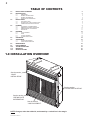
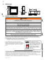
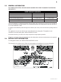
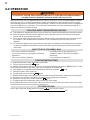
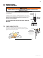
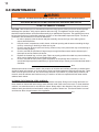
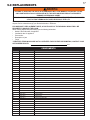
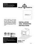
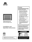
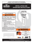
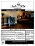
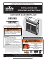
1
INSTALLER: LEAVE THIS MANUAL WITH THE APPLIANCE.
CONSUMER: RETAIN THIS MANUAL FOR FUTURE REFERENCE.
INSTALLATION AND
OPERATING INSTRUCTIONS
CERTIFIED UNDER CANADIAN AND AMERICAN NATIONAL STANDARDS, CR97-003, CAN1-2.21-M85, IAS U.S. 4-96.
OUTDOOR GAS FIREPLACE
GSS36N
NATURAL GAS MODEL
GSS36P
PROPANE GAS MODEL
CERTIFIED FOR CANADA AND UNITED STATES USING ANSI/CSA METHODS.
SAFETY INFORMATION
WARNING
If the information in these instructions are
!
not followed exactly, a fire or explosion
may result causing property damage,
personal injury or loss of life.
- Do not store or use gasoline or other flammable
vapors and liquids in the vicinity of this or any
other appliance.
- WHAT TO DO IF YOU SMELL GAS:
•
Do not try to light any appliance.
•
Do not touch any electrical switch; do not use
any phone in your building.
•
Immediately call your gas supplier from a
neighbour’s phone. Follow the gas supplier’s
instructions.
•
If you cannot reach your gas supplier, call the
fire department.
- Installation and service must be performed by a
qualified installer, service agency or the supplier.
WARNING: FOR OUTDOOR USE ONLY
!
WARNING
HOT GLASS WILL CAUSE
BURNS.
DO NOT TOUCH GLASS UNTIL
COOLED.
NEVER ALLOW CHILDREN TO
TOUCH GLASS.
Wolf Steel Ltd., 24 Napoleon Rd., Barrie, ON, L4M 0G8 Canada /
103 Miller Drive, Crittenden, Kentucky, USA, 41030
Phone (705)721-1212 • Fax (705)722-6031 • www.napoleonfireplaces.com • [email protected]
$10.00
1.22A
W415-0807 / A / 03.30.11
2
TABLE OF CONTENTS
1.0
2.0
3.0
4.0
INSTALLATION OVERVIEW
INTRODUCTION
2
3
2.1
2.2
2.3
2.4
4
4
5
5
INSTALLATION
6
3.1
3.2
3.3
6
6
7
6.0
7.0
8.0
9.0
10.0
11.0
12.0
GAS INSTALLATION
OPTIONAL WALL SWITCH INSTALLATION
COMBUSTION AND VENTILATION AIR
FRAMING
4.1
4.2
4.3
4.4
5.0
DIMENSIONS
GENERAL INSTRUCTIONS
GENERAL INFORMATION
RATING PLATE INFORMATION
7
CLEARANCE TO COMBUSTIBLES
MINIMUM ENCLOSURE CLEARANCES
MINIMUM MANTEL CLEARANCES
NAILING TAB
7
10
11
11
FINISHING
12
5.1
5.2
5.3
5.4
12
13
13
13
LOG PLACEMENT
HOOD
LOGO PLACEMENT
LOUVRE INSTALLATION
OPERATION
ADJUSTMENT
14
15
7.1
7.2
15
15
VENTURI ADJUSTMENT
FLAME CHARACTERISTICS
MAINTENANCE
REPLACEMENTS
TROUBLE SHOOTING
WARRANTY
SERVICE HISTORY
16
17
19
21
22
1.0 INSTALLATION OVERVIEW
See the section
“HOOD
INSTALLATION”.
See the section
“LOUVRE INSTALLATION”.
See the section
“RATING PLATE
INFORMATION”.
See the section
“LOG PLACEMENT”.
NOTE: Changes, other than editorial, are denoted by a vertical line in the margin.
W415-0807 / A / 03.30.11
3
2.0 INTRODUCTION
!
•
•
•
•
•
•
•
•
•
•
•
•
•
•
•
•
•
•
•
•
•
•
•
WARNING
THIS APPLIANCE IS HOT WHEN OPERATED AND CAN CAUSE SEVERE BURNS IF CONTACTED.
Do not operate appliance before reading and understanding operating instructions. Failure to operate
appliance according to operating instructions could cause fire or injury.
Any changes to this appliance or its controls can be dangerous and is prohibited.
Risk of burns. The appliance should be turned off and cooled before servicing.
Do not install damaged, incomplete or substitute components.
Risk of cuts and abrasions. Wear protective gloves and safety glasses during installation. Sheet metal
edges may be sharp.
Do not burn wood or other materials in this appliance.
Provide adequate ventilation and combustion air. Provide adequate accessibility clearance for servicing
and operating the appliance. Never obstruct the front opening of the appliance.
If appliance keeps shutting off, have it serviced. Keep burner and control compartment clean.
Do not allow wind to blow directly into the appliance. Avoid any drafts that alter burner flame patterns.
Children and adults should be alerted to the hazards of high surface temperature and should stay away
to avoid burns or clothing ignition.
Young children should be carefully supervised when they are in the same area as the appliance.
Toddlers, young children and others may be susceptible to accidental contact burns. A physical barrier
is recommended if there are at risk individuals in the vicinity of the appliance. To restrict access to an
appliance, install an adjustable safety gate to keep toddlers, young children and other at risk individuals
away from hot surfaces.
Clothing or other flammable material should not be placed on or near the appliance.
Furniture or other objects must be kept a minimum of 4 feet away from the front of the appliance.
Ensure you have incorporated adequate safety measures to protect infants/toddlers from touching hot
surfaces.
Even after the appliance is off, it will remain hot for an extended period of time.
Check with your local hearth specialty dealer for safety screens and hearth guards to protect children
from hot surfaces. These screens and guards must be fastened to the floor.
Any safety screen or guard removed for servicing must be replaced prior to operating the appliance.
It is imperative that the control compartments, burners and circulating blower and its passageway in
the appliance and venting system are kept clean. The appliance should be inspected before use and
at least annually by a qualified service person. The appliance area must be kept clear and free from
combustible materials, gasoline and other flammable vapors and liquids.
Under no circumstances should this appliance be modified.
Do not use this appliance if any part has been under water. Immediately call a qualified service
technician to inspect the appliance and to replace any part of the control system and any gas control
which has been under water.
Keep the packaging material out of reach of children and dispose of the material in a safe manner. As
with all plastic bags, these are not toys and should be kept away from children and infants.
This appliance must not be installed indoors or within any structure that prevents or inhibits the exhaust
gases from dissipating in the outside atmosphere.
3.14A
W415-0807 / A / 03.30.11
4
2.1
DIMENSIONS
27"
35 1/2"
33"
5 1/2"
1
12 1/4"13 /4"
GAS
INLET
3"
37 3/8"
2.2
GENERAL INSTRUCTIONS
!
WARNING
ALWAYS LIGHT THE PILOT WHETHER FOR THE FIRST TIME OR IF THE GAS SUPPLY HAS RAN OUT,
WITH THE GLASS DOOR OPENED OR REMOVED.
NEVER OBSTRUCT THE FRONT OPENING OF THE APPLIANCE.
OBJECTS PLACED IN FRONT OF THE APPLIANCE MUST BE KEPT A MINIMUM OF 48” FROM THE
FRONT FACE OF THE APPLIANCE.
FIRE RISK. EXPLOSION HAZARD.
HIGH PRESSURE WILL DAMAGE VALVE. DISCONNECT GAS SUPPLY PIPING BEFORE PRESSURE
TESTING GAS LINE AT TEST PRESSURES ABOVE 1/2 PSIG. CLOSE THE MANUAL SHUT-OFF VALVE
BEFORE PRESSURE TESTING GAS LINE AT TEST PRESSURES EQUAL TO OR LESS THAN 1/2 PSIG.
USE ONLY WOLF STEEL APPROVED OPTIONAL ACCESSORIES AND REPLACEMENT PARTS WITH
THIS APPLIANCE. USING NON-LISTED ACCESSORIES (BLOWERS, DOORS, LOUVRES, TRIMS, GAS
COMPONENTS, VENTING COMPONENTS, ETC.) COULD RESULT IN A SAFETY HAZARD AND WILL
VOID THE WARRANTY AND CERTIFICATION.
THE APPLIANCE IS ONLY FOR USE WITH THE TYPE OF GAS INDICATED ON THE RATING PLATE.
THIS APPLIANCE IS NOT CONVERTIBLE FOR USE WITH OTHER GASES.
THIS GAS APPLIANCE SHOULD BE INSTALLED AND SERVICED BY A QUALIFIED INSTALLER to
conform with local codes. Installation practices vary from region to region and it is important to know the
specifics that apply to your area, for example in Massachusetts State:
• The appliance off valve must be a “T” handle gas cock.
• The flexible connector must not be longer than 36 inches.
The installation must conform with local codes or, in
absence of local codes, the National Gas and Propane
Installation Code CSA B149.1 in Canada, or the National
Fuel Gas Code, ANSI Z223.1 / NFPA 54 in the United
States.
www.nficertified.org
We suggest that our gas
hearth products be installed
and serviced by professionals
who are certified in the U.S.
by the National Fireplace
Institute® (NFI) as NFI Gas
Specialists
4.3A
The appliance and its individual shutoff valve must be disconnected from the gas supply piping system during
any pressure testing of that system at test pressures in excess of 1/2 psig (3.5 kPa). The appliance must be
isolated from the gas supply piping system by closing its individual manual shutoff valve during any pressure
testing of the gas supply piping system at test pressures equal to or less than 1/2 psig (3.5 kPa).
When the appliance is installed directly on combustible material other than wood flooring, the appliance shall
be installed on a metal or wood panel extending the full width and depth.
W415-0807 / A / 03.30.11
5
2.3
GENERAL INFORMATION
FOR YOUR SATISFACTION, THIS APPLIANCE HAS BEEN TEST-FIRED TO ASSURE ITS OPERATION
AND QUALITY!
RATES AND EFFICIENCIES
Altitude
Maximum Input
Minimum Inlet Gas Supply Pressure
Maximum Inlet Gas Supply Pressure
Manifold Pressure Under Flow Conditions
NATURAL GAS
PROPANE GAS
0 - 2,000*
0 - 2,000*
40,000 BTU/hr
40,000 BTU/hr
4.5” Water Column
11” Water Column
7” Water Column
13” Water Column
3.5” Water Column
10” Water Column
* When the appliance is installed at elevations above 2,000ft, and in the absence of specific recommendations
from the local authority having jurisdiction, the certified high altitude input rating shall be reduced at the rate of
4% for each additional 1,000ft.
It is highly recommended to protect the logs from moisture (rain, snow). Cover the enclosure opening when not
in use.
This appliance is only for use with the type of gas indicated on the rating plate. This appliance is not
convertible for use with other gases, unless a certified kit is used.
No external electricity (110 volts or 24 volts) is required for the gas system operation.
Expansion / contraction noises during heating up and cooling down cycles are normal and are to be expected.
RATING PLATE INFORMATION
For rating plate location, see “INSTALLATION OVERVIEW” section.
This illustration is for reference only. Refer to the rating plate on the appliance for accurate information.
A
M
P
MODEL
LE
CERTIFIED UNDER / HOMOLOGUÉ SELON LES NORMES: CGA CR97-003 (July, 1997) CSA US Req. 4-96, 3rd Ed. OUTDOOR
R GAS FIR
FIRE
FIREPLACE / FOYER AU GAZ EXTÉRIEUR
S
2.4
WOLF STEEL LTD.
24 NAPOLEON ROAD. BARRIE, ONTARIO L4M 0G8
CANADA
8 CANA
CANAD
GSS36/CSS36
i
W415-0807 / A / 03.30.11
6
3.0 INSTALLATION
3.1
GAS INSTALLATION
!
WARNING
RISK OF FIRE, EXPLOSION OR ASPHYXIATION. ENSURE THERE ARE NO IGNITION SOURCES SUCH AS
SPARKS OR OPEN FLAMES.
SUPPORT GAS CONTROL WHEN ATTACHING GAS SUPPLY PIPE TO PREVENT DAMAGING GAS LINE.
ALWAYS LIGHT THE PILOT WHETHER FOR THE FIRST TIME OR IF THE GAS SUPPLY HAS RUN OUT
WITH THE GLASS DOOR OPENED OR REMOVED. PURGING OF THE GAS SUPPLY LINE SHOULD BE
PERFORMED BY A QUALIFIED SERVICE TECHNICIAN. ASSURE THAT A CONTINUOUS GAS FLOW IS AT
THE BURNER BEFORE CLOSING THE DOOR. ENSURE ADEQUATE VENTILATION. FOR GAS AND
ELECTRICAL LOCATIONS, SEE “DIMENSION” SECTION.
ALL GAS CONNECTIONS MUST BE CONTAINED WITHIN THE APPLIANCE WHEN COMPLETE.
HIGH PRESSURE WILL DAMAGE VALVE. DISCONNECT GAS SUPPLY PIPING BEFORE TESTING GAS
LINE AT TEST PRESSURES ABOVE 1/2 PSIG.
VALVE SETTINGS HAVE BEEN FACTORY SET, DO NOT CHANGE.
Installation and servicing to be done by a qualified installer.
A.
Move the appliance into position and secure.
B.
If equipped with a flex connector the appliance is designed to accept a 1/2” gas supply. Without the
connector it is designed to accept a 3/8” gas supply. The appliance is equipped with a manual shut off
valve to turn off the gas supply to the appliance.
C.
Connect the gas supply in accordance to local codes. In the absence of local codes, install to the
current CAN/CSA-B149.1 Installation Code in Canada or to the current National Fuel Gas Code, ANSI
Z223.1 / NFPA 54 in the United States.
D.
When flexing any gas line, support the gas valve so that the lines are not bent or kinked.
E.
The gas line flex-connector should be installed to provide sufficient movement for shifting the burner
assembly on it’s side to aid with servicing components.
F.
Check for gas leaks by brushing on a soap and water solution. Do not use open flame.
30.1A
OPTIONAL WALL SWITCH INSTALLATION
!
WARNING
DO NOT CONNECT EITHER THE WALL SWITCH, THERMOSTAT OR GAS VALVE DIRECTLY TO 110
VOLT ELECTRICITY.
ILO
For ease of accessibility, an optional remote wall switch or millivolt thermostat may be installed in a convenient
location. Route a 2 strand, solid core millivolt wire from the valve to the wall switch or millivolt thermostat. The
recommended maximum lead length depends on wire size:
WIRE SIZE
MAX. LENGTH
14 gauge
100 feet
P
TP
16 gauge
60 feet
18 gauge
40 feet
T
3.2
Disconnect the existing wires from terminals 1 and 3 (from the
ON/OFF switch) and replace with the leads from the wall switch / millivolt thermostat.
50.3
W415-0807 / A / 03.30.11
7
3.3
COMBUSTION AND VENTILATION AIR
This appliance is intended for installation on an outdoor patio or in your yard. It must never be installed inside
the warm air envelope of your structure.
It is highly recommended that this appliance be installed in a “sheltered” area. Direct wind will cause an erratic
flame and possible pilot or main burner outage.
An erratic flame could also lead to excessive carboning (black soot), this condition is not a safety issue but is
visually undesirable.
Typical installation may include covered patio, screened porch, gazebo or on an outside the wall of a house.*
NOTE: Ensure the area has adequate ventilation.
4.0 FRAMING
4.1
CLEARANCE TO COMBUSTIBLES
!
WARNING
RISK OF FIRE!
IN ORDER TO AVOID THE POSSIBILITY OF EXPOSED INSULATION OR VAPOUR BARRIER COMING
IN CONTACT WITH THE APPLIANCE BODY, IT IS RECOMMENDED THAT THE WALLS OF THE
APPLIANCE ENCLOSURE BE “FINISHED” (IE: DRYWALL / SHEETROCK), AS YOU WOULD FINISH
ANY OTHER OUTSIDE WALL OF A HOME. THIS WILL ENSURE THAT CLEARANCE TO
COMBUSTIBLES IS MAINTAINED WITHIN THE CAVITY.
DO NOT NOTCH THE FRAMING AROUND THE APPLIANCE STAND-OFFS. FAILURE TO MAINTAIN
AIR SPACE CLEARANCE MAY CAUSE OVER HEATING AND FIRE. PREVENT CONTACT WITH
SAGGING OR LOOSE INSULATION OR FRAMING AND OTHER COMBUSTIBLE MATERIALS. BLOCK
OPENING INTO THE CHASE TO PREVENT ENTRY OF BLOWN-IN INSULATION. MAKE SURE
INSULATION AND OTHER MATERIALS ARE SECURED.
WHEN CONSTRUCTING THE ENCLOSURE ALLOW FOR FINISHING MATERIAL THICKNESS TO
MAINTAIN CLEARANCES. FRAMING OR FINISHING MATERIAL CLOSER THAN THE MINIMUMS
LISTED MUST BE CONSTRUCTED ENTIRELY OF NON-COMBUSTIBLE MATERIALS. MATERIALS
CONSISTING ENTIRELY OF STEEL, IRON, BRICK, TILE, CONCRETE, SLATE, GLASS OR PLASTERS,
OR ANY COMBINATION THEREOF ARE SUITABLE. MATERIALS THAT ARE REPORTED AS PASSING
ASTM E 136, STANDARD TEST METHOD FOR BEHAVIOUR OF MATERIALS IN A VERTICAL TUBE
FURNACE AT 750°C AND UL763 SHALL BE CONSIDERED NON-COMBUSTIBLE MATERIALS.
MINIMUM CLEARANCE TO COMBUSTIBLES MUST BE MAINTAINED OR A SERIOUS FIRE HAZARD
COULD RESULT.
THE APPLIANCE REQUIRES A MINIMUM ENCLOSURE HEIGHT. MEASURE FROM THE APPLIANCE
BASE.
IF STEEL STUD FRAMING KITS WITH CEMENT BOARD ARE PROVIDED, THEY MUST BE
INSTALLED.
71.1
* If installing a propane appliance the propane cylinder must always be on the exterior of such a
structure.
W415-0807 / A / 03.30.11
8
Minimum Clearance to Combustibles construction from appliance and vent surfaces:
Framing
0” to stand-offs
Finishing
0” to back, sides and bottom
Non-combustible finishing
4 1/2” to top
Recessed depth
13 1/4“
Enclosure top
39 1/4” from bottom of appliance
Clearance to ceiling
84” from bottom of appliance.
It is recommended that the walls of the appliance enclosure be finished. This would ensure that clearance to
combustibles is maintained within the cavity.
It is best to frame your appliance after it is positioned. Use 2x4’s and frame to local building codes.
35 / "
34
1 "
13 /2
3"
5 1 /2" 1 /2"
37
OUTSIDE
CHASE
13 1/2"
37 1/2"
W415-0807 / A / 03.30.11
1 2
37
52 / "
"
36 3/4"
INSIDE
CHASE
13 1/2"
37 1/2"
6"
2' MIN.
9
!
WARNING
USE ONLY NON-COMBUSTIBLE MATERIAL SUCH AS CEMENT BOARD, CERAMIC TILE, MARBLE,
ETC. WHEN FINISHING TO THE APPLIANCE. DO NOT USE WOOD OR DRYWALL.
Combustible materials may be installed
flush with the front of the appliance but
must not cover any of the outer frame
face-areas of the appliance. Noncombustible material (brick, stone or
ceramic tile) may protrude in these areas.
It is not necessary to install a hearth
extension with this appliance.
When roughing in the appliance, raise
the appliance to accommodate for the
thickness of the finished floor materials,
i.e. tile, carpeting, hard wood, which if
not planned for will interfere with the
opening of the lower access door and the
installation of many decorative flashing
accessories.
4 1/2”
(MIN)
33”
W415-0807 / A / 03.30.11
10
4.2
MINIMUM ENCLOSURE CLEARANCES
COMBUSTIBLE
6 1/4”
4 1/2”
NONCOMBUSTIBLE
39 1/4”
1”
The appliance requires a minimum enclosure height of 39 1/4”. For temperature requirements, the enclosure
space around and above the appliance must be left unobstructed.
W415-0807 / A / 03.30.11
11
4.3
MINIMUM MANTEL CLEARANCES
!
WARNING
RISK OF FIRE, MAINTAIN ALL SPECIFIED AIR SPACE CLEARANCES TO COMBUSTIBLES. FAILURE
TO COMPLY WITH THESE INSTRUCTIONS MAY CAUSE A FIRE OR CAUSE THE APPLIANCE TO
OVERHEAT. ENSURE ALL CLEARANCES (I.E. BACK, SIDE, TOP, VENT, MANTEL, FRONT, ETC.) ARE
CLEARLY MAINTAINED.
WHEN USING PAINT OR LACQUER TO FINISH THE MANTEL, THE PAINT OR LACQUER MUST BE
HEAT RESISTANT TO PREVENT DISCOLOURATION.
73.1
We recommend all mantels made from non-combustible material. If using combustible materials, follow the
chart below.
NOTE: Mantel temperatures will rise above normal temperatures and may be hot to the touch.
M
A
N
T
E
L
17
H
E
,
*
H
T
14
16
7” MANTEL
15
6” MANTEL
4” MANTEL
17”
2” MANTEL
16”
14”
12”
13
12
TOP OF UNIT
0
2
4
6
8
MANTEL DEPTH
4.4
NAILING TAB
To install the appliance face flush with the finished surface, position the
framework to accommodate the thickness of the finished surface. Bend out the
four nailing tabs, attached on either side of the appliance and secure to the 2x4
framing. The tabs will facilitate the installation of either a 3/4” or a 1” finished
surface thickness. The nailing tabs must not be removed.
NAILING
TAB
W415-0807 / A / 03.30.11
12
5.0 FINISHING
5.1
LOG PLACEMENT
!
WARNING
FAILURE TO POSITION THE LOGS IN ACCORDANCE WITH THESE DIAGRAMS OR FAILURE TO USE
ONLY LOGS SPECIFICALLY APPROVED WITH THIS APPLIANCE MAY RESULT IN PROPERTY
DAMAGE OR PERSONAL INJURY.
LOGS MUST BE PLACED IN THEIR EXACT LOCATION IN THE APPLIANCE. DO NOT MODIFY THE
PROPER LOG POSITIONS, SINCE APPLIANCE MAY NOT FUNCTION PROPERLY AND DELAYED
IGNITION MAY OCCUR.
THE LOGS ARE FRAGILE AND SHOULD BE HANDLED WITH CARE.
76.1A
TM
PHAZER logs and glowing embers exclusive to Napoleon, provide a unique and realistic glowing effect that is
different in every installation. Take the time to carefully position the glowing embers for a maximum glowing effect.
Log colours may vary. During the initial use of the appliance, the colours will become more uniform as colour
pigments burn in during the heat activated curing process.
A.
Place the rear log so that it rests against
the two log brackets on the back wall of the
firebox. The air space between the log and
firebox back is used to facilitate combustion air
flow.
B.
Move the charcoal strip into position lining
up the holes in the bottom with the studs
located on the burner on the burner. Ensure
strip sits flat on the burner.
C.
Position the front right log just behind the
grate lining up the holes in the bottom with
the studs located on the log support.
D.
Move the left log into position lining up the
hole in the bottom with the stud on the left
side of the log support.
E.
Line up the square hole in the right crossover
with the square post located on the right side
of log and install as shown.
F.
Line up the rectangular hole in the left
crossover with the rectangular post located on
the left side of log and install as shown.
IMPORTANT
IT IS HIGHLY RECOMMENDED TO PROTECT THE LOGS FROM MOISTURE.
COVER THE FIREBOX WHEN NOT IN USE.
W415-0807 / A / 03.30.11
13
5.2
HOOD
The curtain mesh must be kept fully closed during operation to help
prevent accidental burns from occurring.
HOOD
The heater must not be used when the hood is removed. Hook
the hood over the lip of the curtain
support plate.
5.3
CURTAIN
MESH
LOGO PLACEMENT
Remove the backing of the logo supplied and place on the screen cover, as indicated.
5.4
LOUVRE INSTALLATION
HOOD
BRACKET
SLOT
HINGE SCREEN
A
C
HINGE SCREEN: Position the hinge screen into
place and with the control door open, secure to the
firebox using three screws.
LOUVRE
B
UPPER LOUVRES: Insert the
upper louvres into the slots
on both brackets. Press the
top flange of the hood into
the four clips located along
the top of the appliance as
shown.
LOWER LOUVRES: Attach
each hinge to the firebox with
2 screws.
LOWER LOUVRES
(VALVE CONTROL DOOR)
W415-0807 / A / 03.30.11
14
6.0 OPERATION
!
WARNING
IF YOU DO NOT FOLLOW THESE INSTRUCTIONS EXACTLY, A FIRE OR EXPLOSION MAY RESULT
CAUSING PROPERTY DAMAGE, PERSONAL INJURY OR LOSS OF LIFE.
When lit for the first time, the appliance will emit an odor for a few hours. This is a normal temporary condition
caused by the “burn-in” of paints and lubricants used in the manufacturing process and will not occur again.
After extended periods of non-operation such as following a vacation or a warm weather season, the appliance
may emit a slight odor for a few hours. This is caused by dust particles in the heat exchanger burning off. In
both cases, sufficiently ventilate the area.
FOR YOUR SAFETY READ BEFORE LIGHTING:
A. This appliance is equipped with a pilot which must be lit by hand while following these instructions exactly.
B. Before operating smell all around the appliance area for gas and next to the floor because some gas is
heavier than air and will settle on the floor.
C. Use only your hand to turn the gas control knob. Never use tools. If the knob will not turn by hand, do not
try to repair it. Call a qualified service technician. Force or attempted repair may result in a fire or
explosion.
D. Do not use this appliance if any part has been under water. Immediately call a qualified service technician
to inspect the appliance and replace any part of the control system and any gas control which has been
under water.
WHAT TO DO IF YOU SMELL GAS:
• Do not use a mobile or land phone.
• If you cannot reach your gas supplier, call the fire
department.
• Do not try to light any appliance.
• Immediately call your gas supplier from a
neighbour’s phone. Follow the gas supplier’s
instructions.
• Turn off all gas to the appliance.
LIGHTING INSTRUCTIONS:
1. Stop! Read the above safety information on this label.
2. Turn the gas knob clockwise
to off.
3. Wait five (5) minutes to clear out any gas. If you smell gas including near the floor, STOP! Follow “B” in the
above safety information on this label. If you don’t smell gas go to the next step.
4. If the appliance is equipped with flame adjustment valve turn clockwise
to off.
5. Find pilot located in front of back log.
6. Turn gas knob counter-clockwise
to pilot.
7. Depress and hold gas knob while lighting the pilot with the push button igniter. Keep knob fully depressed
for one minute, then release. If pilot does not continue to burn repeat steps 3 through 7.
8. With pilot lit, turn gas knob counter-clockwise
to on.
9. If equipped with flame adjustment valve, push and turn knob to high.
10. If equipped with remote on-off switch, main burner may not come on when you turn the valve to on or high.
Remote switch must be in the on position to ignite burner.
TO TURN OFF GAS:
Push in gas control knob slightly and turn clockwise
to off. DO NOT FORCE.
47.9
W415-0807 / A / 03.30.11
15
7.0 ADJUSTMENT
7.1
VENTURI ADJUSTMENT
!
WARNING
CARBON CAN BE DISTRIBUTED IN SURROUNDING LIVING AREA IF THE AIR SHUTTER IS
IMPROPERLY ADJUSTED.
49.5
This appliance has an air shutter that has been factory set open according
to the chart below:
Regardless of venturi orientation, closing the air shutter will cause a more
yellow flame, but can lead to carboning. Opening the air shutter will cause a
more blue flame, but can cause flame lifting from the burner ports. The
flame may not appear yellow immediately; allow 15 to 30 minutes for the
final flame colour to be established.
VENTURI
BURNER
AIR
SHUTTER
OPENING
ORIFICE
AIR SHUTTER ADJUSTMENT MUST ONLY BE DONE BY A QUALIFIED
INSTALLER!
49.1
GSS36
7.2
NG
3/16”
LP
1/4”
FLAME CHARACTERISTICS
It’s important to periodically perform a visual check of the pilot and
burner flames. Compare them to the illustrations provided. If any flames
appear abnormal call a service person.
3/8” - 1/2”
FLAME MUST
ENVELOPE UPPER
3/8" TO 1/2" OF
THERMOCOUPLE &
THERMOPILE
54.2
W415-0807 / A / 03.30.11
16
8.0 MAINTENANCE
MAINTENANCE
! WARNING
MAINTENANCE
TURN OFF THE GAS AND ELECTRICAL POWER BEFORE SERVICING THE APPLIANCE.
APPLIANCE MAY BE HOT, DO NOT SERVICE UNTIL APPLIANCE HAS COOLED.
DO NOT USE ABRASIVE CLEANERS.
CAUTION: Label all wires prior to disconnection when servicing controls. Wiring errors can cause improper
and dangerous operation. Verify proper operation after servicing. This appliance and its venting system
should be inspected before use and at least annually by a qualified service person. The appliance area must
be kept clear and free of combustible materials, gasoline or other flammable vapors and liquids. The flow of
combustion and ventilation air must not be obstructed.
1.
In order to properly clean the burner and pilot assembly, remove the logs, rocks and/or glass to
expose both assemblies.
2.
Keep the control compartment, media, burner, air shutter opening and the area surrounding the logs
clean by vacuuming or brushing, at least once a year.
3.
Check to see that all burner ports are burning. Clean out any of the ports which may not be burning or
are not burning properly.
4.
Check to see that the pilot flame is large enough to engulf the flame sensor and/or thermocouple /
thermopile as well as reaches the burner.
5.
Replace the cleaned logs, rocks or glass. Failure to properly position the media may cause carboning
which can be distributed in the surrounding living area.
6.
Check to see that the main burner ignites completely on all openings when turned on. A 5 to 10
second total light-up period is satisfactory. If ignition takes longer, consult your local authorized dealer /
distributor.
40.16
Stainless steel tends to oxidize or stain in the presence of chlorides and sulfides, particularly in coastal areas
and other harsh environments, such as the warm, highly humid atmosphere around pools and hot tubs. These
stains could be perceived as rust, but can be easily removed or prevented. To provide stain prevention and
removal, wash all stainless steel surfaces every 3-4 weeks or as often as required with fresh water and/or
stainless steel cleaner.
CLEANING THE STAINLESS STEEL SURFACE:
Do not use abrasive cleaners or steel wool on the stainless steel parts. Doing so will scratch the finish. Surfaces should be cleaned with warm soapy water while the metal is still warm to the touch. To clean stainless
surfaces, use a stainless steel or non-abrasive cleaner. Always wipe in the direction of the grain. Over time,
stainless steel parts discolour when heated, usually to a golden or brown hue. This discolouration is normal
and does not affect the performance of the appliance.
81.1
W415-0807 / A / 03.30.11
17
9.0 REPLACEMENTS
!
WARNING
FAILURE TO POSITION THE PARTS IN ACCORDANCE WITH THIS MANUAL OR FAILURE TO USE
ONLY PARTS SPECIFICALLY APPROVED WITH THIS APPLIANCE MAY RESULT IN PROPERTY
DAMAGE OR PERSONAL INJURY.
** THIS IS A FAST ACTING THERMOCOUPLE. IT IS AN INTEGRAL SAFETY COMPONENT. REPLACE ONLY WITH
A FAST ACTING THERMOCOUPLE SUPPLIED BY WOLF STEEL LTD.
Contact your dealer or the factory for questions concerning prices and policies on replacement parts. Normally
all parts can be ordered through your Authorized dealer / distributor.
FOR WARRANTY REPLACEMENT PARTS, A PHOTOCOPY OF THE ORIGINAL INVOICE WILL BE
REQUIRED TO HONOUR THE CLAIM.
When ordering replacement parts always give the following information:
• Model & Serial Number of appliance
• Installation date of appliance
• Part number
• Description of part
• Finish
* IDENTIFIES ITEMS WHICH ARE NOT ILLUSTRATED. FOR FURTHER INFORMATION, CONTACT YOUR
AUTHORIZED DEALER.
41.2
COMPONENTS
REF NO.
PART NO.
DESCRIPTION
1
W357-0001
PIEZO IGNITER
2
W680-0004
THERMOPILE
3
W680-0005
THERMOCOUPLE**
4
W010-0801
NATURAL GAS PILOT ASSEMBLY
4
W010-0800
PROPANE GAS PILOT ASSEMBLY
5
W455-0069
NATURAL GAS PILOT INJECTOR
5
W455-0067
PROPANE GAS PILOT INJECTOR
6
W725-0028
NATURAL GAS VALVE
6
W725-0029
PROPANE GAS VALVE
7*
W385-0334
NAPOLEON® LOGO
8
GL-667
LOG SET
9
W135-0378
BACK LOG (#1)
10
W135-0381
LEFT MIDDLE LOG (#2)
11
W135-0382
RIGHT MIDDLE LOG (#3)
12
W135-0380
LEFT CROSSOVER LOG (#4)
13
W135-0383
CHARCOAL STRIP
14
W135-0379
RIGHT CROSSOVER LOG (#6)
15
W010-1066
PAN BURNER
16
W456-0031
#31 NATURAL GAS BURNER ORIFICE
16
W456-0049
#49 PROPANE GAS BURNER ORIFICE
17
W335-0033
HOOD
18
W565-0062
CURTAIN MESH
19
W555-0040
CURTAIN ROD
20*
W080-0614
CURTAIN ROD BRACKET
21
W500-0209
CURTAIN SUPPORT PLATE
22
W630-0010
BLACK TASSELS
23
W200-0135
FIREBOX COVER
24
N325-0036
COVER HANDLE
25*
W660-0005
SWITCH
26*
W750-0109
3
27*
W750-0110
1
28
W010-1037
LOUVRE KIT - STAINLESS STEEL
/16” FLAG WIRE ASSEMBLY
/4” FLAG WIRE ASSEMBLY
W415-0807 / A / 03.30.11
18
2
23
**3
6
5
28
17
4
8
24
16
19
21
9
15
11
10
22
1
12
13
14
18
W415-0807 / A / 03.30.11
10.0
19
TROUBLE SHOOTING
!
WARNING
ALWAYS LIGHT THE PILOT WHETHER FOR THE FIRST TIME OR IF THE GAS SUPPLY HAS RAN OUT,
WITH THE GLASS DOOR OPEN OR REMOVED.
TURN OFF THE GAS AND ELECTRICAL POWER BEFORE SERVICING THE APPLIANCE.
APPLIANCE MAY BE HOT, DO NOT SERVICE UNTIL APPLIANCE HAS COOLED.
DO NOT USE ABRASIVE CLEANERS.
SYMPTOM
Main burner goes out; pilot
stays on.
PROBLEM
TEST SOLUTION
Pilot flame is not large
enough or not engulfing the
thermopile.
-
Turn up the pilot flame.
Replace pilot assembly.
Thermopile shorting.
-
Clean thermopile connection tot he valve. Reconnect.
Replace thermopile / valve.
Remote wall switch wire is too
long; too much resistance in
the system.
-
Shorten wire to connect length or wire gauge.
Faulty thermostat or switch.
-
Replace.
Main burner goes out; pilot
goes out.
Refer to “MAIN BURNER GOES OUT; PILOT STAYS ON”
Pilot goes out when the
gas knob is released.
The gas valve has an
interlock device which
will not allow the pilot
burner to be lit until
the thermocouple
has cooled. Allow
approximately 60
seconds for the
thermocouple to cool.
System is not correctly
purged.
Pilot burning; no gas to
main burner; gas knob
is on ‘HI’; wall switch /
thermostat is on.
Pilot will not light.
-
Purge the gas line.
Out of propane gas.
-
Fill the tank.
Pilot flame is not large
enough.
-
Turn up the pilot flame.
Pilot flame is not engulfing the
thermocouple
-
Gently twist the pilot head to improve the flame pattern
around the thermocouple.
Thermocouple shorting / faulty.
-
Loosen and tighten thermocouple.
Clean thermocouple and valve connection.
Replace thermocouple.
Replace valve.
Faulty valve.
-
Replace.
Thermostat or switch is
defective
-
Connect a jumper wire across the wall switch terminals;
if main burner lights, replace switch / thermostat.
Wall switch wiring is defective.
-
Disconnect the switch wires & connect a jumper wire
across terminals 1 & 3; if the main burner lights, check
the wires for defects and/or replace wires.
Main burner orifice is plugged.
-
Remove stoppage in orifice.
Faulty valve.
-
Replace.
No spark at pilot burner.
-
-
Check if pilot can be lit by a match.
Check that the wire is connected to the push button
igniter.
Check if the push button igniter needs tightening.
Replace the wire if the wire insulation is broken or frayed.
Replace the electrode if the ceramic insulator is cracked
or broken.
Replace the push button ignitor
Out of propane gas.
-
Fill the tank.
Spark gap is incorrect.
-
Spark gap should be 0.150” to 0.175” (5/32” to 11/64”
approx.) from the electrode tip and the pilot burner. To
ensure proper electrode location, tighten securing nut
(finger tight plus 1/4 turn).
No gas at the pilot burner.
-
Check that the manual valve is turned on.
Check the pilot orifice for blockage.
Replace the valve.
Call the gas distributor.
PILOT
BURNER THERMOPILE
-
THERMOCOUPLE
42.10
W415-0807 / A / 03.30.11
20
SYMPTOM
Pilot goes out while
standing; Main burner is in
‘OFF’ position.
PROBLEM
Gas piping is undersized.
TEST SOLUTION
-
Flames are consistently
too large or too small.
Carboning occurs.
Unit is over-fired or underfired.
P
-
-
ILO
T
-
Carbon is being deposited
on logs or combustion
chamber surfaces.
White / grey film forms.
Remote wall switch is in
’OFF’ position; main burner
comes on when gas knob
is turned to ‘ON’ position.
Turn on all gas appliances and see if pilot flame flutters,
diminishes or extinguishes, especially when main burner
ignites. Monitor appliance supply working pressure.
Check if supply piping size is to code. Correct all
undersized piping.
Check pressure readings:
Inlet pressure can be checked by turning screw (A)
counter-clockwise 2 or 3 turns and then placing pressure
gauge tubing over the test point. Gauge should read
7” (minimum 4.5”) water column for natural gas or 13”
(minimum 11”) water column for propane. Check that
main burner is operating on ‘HI’.
Outlet pressure can be checked the same as above
using screw (B). Gauge should read 3.5” water column
for natural gas or 10” water column for propane. Check
that main burner is operating on ‘HI’.
AFTER TAKING PRESSURE READINGS, BE SURE TO
TURN SCREWS CLOCKWISE FIRMLY TO RESEAL.
DO NOT OVER TORQUE.
Leak test with a soap and water solution.
Air shutter has become
blocked.
-
Ensure air shutter opening is free of lint or other
obstructions.
Flame is impinging on the logs
or combustion chamber.
-
Check that the logs are correctly positioned.
Open air shutter to increase the primary air.
Check the input rate: check the manifold pressure and
orifice size as specified by the rating plate values.
Sulphur from fuel is being
deposited on glass, logs or
combustion chamber surfaces.
-
Clean the glass with a recommended gas appliance
glass cleaner.
DO NOT CLEAN GLASS WHEN HOT.
If deposits are not cleaned off regularly, the glass may
become permanently marked.
-
Wall switch is mounted upside
down.
-
Reverse.
Remote wall switch is
grounding.
-
Replace.
Remote wall switch wire is
grounding.
-
Check for ground (short); repair ground or replace wire.
Faulty valve.
-
Replace.
42.10_2
W415-0807 / A / 03.30.11
21
11.0
WARRANTY
NAPOLEON® gas appliances are manufactured under the strict Standard of the world recognized
ISO 9001 : 2008 Quality Assurance Certificate.
NAPOLEON® products are designed with superior components and materials, assembled by trained craftsmen who take
great pride in their work. The burner and valve assembly are leak and test-fired at a quality test station. Once assembled
the complete appliance is thoroughly inspected by a qualified technician before packaging to ensure that you, the customer,
receives the quality product that you expect from NAPOLEON®.
NAPOLEON® GAS APPLIANCE 5 YEAR LIMITED WARRANTY
All stainless steel components of your new NAPOLEON® gas appliance are warranted against defects for
five years.
All parts such as gas valves, logs, gasketing are covered and NAPOLEON® will provide replacement parts
free of charge during the first year of the limited warranty.*
Labour related to warranty repair is covered free of charge during the first year. Repair work, however,
requires the prior approval of an authorized company official. Labour costs to the account of NAPOLEON®
are based on a predetermined rate schedule and any repair work must be done through an authorized
NAPOLEON® dealer.
* Construction of models vary. Warranty applies only to components included with your specific appliance.
CONDITIONS AND LIMITATIONS
NAPOLEON® warrants its products against manufacturing defects to the original purchaser only. Registering your warranty is not necessary.
Simply provide your proof of purchase along with the model and serial number to make a warranty claim. NAPOLEON® reserves the right to have
its representative inspect any product or part thereof prior to honouring any warranty claim. Provided that the purchase was made through an
authorized NAPOLEON® dealer your appliance is subject to the following conditions and limitations:
Warranty coverage begins on the date of original installation.
This limited warranty applies only while the unit remains at the site of original installation, and only if the unit is installed in Canada or the United
States.
This factory warranty is nontransferable and may not be extended whatsoever by any of our representatives.
Installation must be done in accordance with the installation instructions included with the product and all local and national building and fire codes.
This limited warranty does not cover damages caused by misuse, lack of maintenance, accident, alterations, abuse or neglect and parts installed
from other manufacturers will nullify this warranty.
This limited warranty further does not cover any scratches, dents, corrosion or discolouring caused by excessive heat, abrasive and chemical
cleaners, mechanical breakage of logs and embers.
In the first year only, this warranty extends to the repair or replacement of warranted parts which are defective in material or workmanship provided
that the product has been operated in accordance with the operation instructions and under normal conditions.
After the first year, with respect to this Limited Warranty, NAPOLEON® may, at its discretion, fully discharge all obligations with respect to this
warranty by refunding to the original warranted purchaser the wholesale price of any warranted but defective part(s).
After the first year, NAPOLEON® will not be responsible for installation, labour or any other costs or expenses related to the reinstallation of a
warranted part, and such expenses are not covered by this warranty.
Notwithstanding any provisions contained in this Limited Warranty, NAPOLEON’S responsibility under this warranty is defined as above and it shall
not in any event extend to any incidental, consequential or indirect damages.
This warranty defines the obligations and liability of NAPOLEON® with respect to the NAPOLEON® gas appliance and any other warranties
expressed or implied with respect to this product, its components or accessories are excluded.
This limited warranty does not cover damages resulting from the use of components not supplied with the appliance, or the use of fuel other than
those specified.
Any damages to appliance due to weather, long periods of dampness, condensation, damaging chemicals or cleaners will not be the responsibility
of NAPOLEON®.
The bill of sale or copy will be required together with a serial number and a model number when making any warranty claims from your authorized
dealer. The warranty registration card must be returned within fourteen days to register the warranty.
NAPOLEON® reserves the right to have its representative inspect any product or part thereof prior to honouring any warranty claim.
All parts replaced under the Limited warranty policy are subject to a single claim.
All parts replaced under the warranty will be covered for a period of 90 days from the date of their installation.
The manufacturer may require that defective parts or products be returned or that digital pictures be provided to support the claim. Returned
products are to be shipped prepaid to the manufacturer for investigation. If a product is found to be defective, the manufacturer will repair or replace
such defect.
Before shipping your appliance or defective components, your dealer must obtain an authorization number. Any merchandise shipped without
authorization will be refused and returned to sender.
Shipping costs are not covered under this warranty.
Additional service fees may apply if you are seeking warranty service from a dealer.
Labour, travel, diagnostic tests, shipping and other related charges are not covered by this warranty.
ALL SPECIFICATIONS AND DESIGNS ARE SUBJECT TO CHANGE WITHOUT PRIOR NOTICE DUE TO ON-GOING PRODUCT IMPROVEMENTS.
NAPOLEON® IS A REGISTERED TRADEMARK OF WOLF STEEL LTD.
2.9B
W415-0807 / A / 03.30.11
22
12.0
SERVICE HISTORY
43.1
W415-0807 / A / 03.30.11
23
13.0
NOTES
44.1
W415-0807 / A / 03.30.11
24
44.1
W415-0807 / A / 03.30.11