Transcript
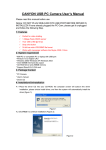
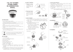
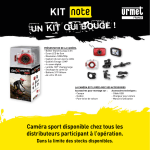
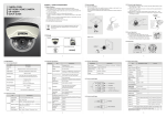
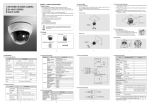
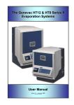
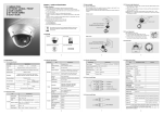
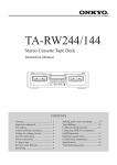
◐ DIMENSION
Ø100
101
2. R
emoving the dome : Lift
the dome. When you push
the latch button, it is unlocked
and you can lift the dome.
3. Camera installation :
(1) Fix the camera set with the supplied screws on ceiling or wall
mount. If you don't use supplied screws, the camera may fall off.
(2) Please refer to '4. Camera angle adjustment' regarding adjust
camera angle.
(3) Re-assemble the camera.
48.1
HD-TVI 3-AXIS DAY & NIGHT
IR DOME CAMERA
SK-D300IR(D)-HT12
MANUAL
Ø130.8
Ø109
◐ ASSEMBLY
DOME COVER ASS'Y
CAMERA MODULE ASS'Y
<Ceiling mount>
LED COVER
Hole
SCREW
LED COVER FORM
CONTROL PCB ASS'Y
◐ PRECAUTION
1. Do not install the camera outdoors.
2. Choose an ideal location for the camera, since a camera unit must
be protected against moisture and vibration.
3. Be careful not to scratch the camera unit, especially lens or dome
cover.
4. Use the camera within the temperature(-45℃~50℃).
5. Handle with care. Dropping it can cause serious damage to the
camera.
6. Avoid any direct sun light toward the lens.
7. Use the AC adaptor 12V DC, 0.5A regulated. Dual voltage product
can use 24V AC adaptor.(option)
HARNESS
SCREW TP1 M3x10 SCREW
3.5x20 2EA
Fix the disk
(Pan angle)
using by a
screw driver
on M3X10
screws
in the holes
Take off the
marked part
by using nipper
for lpacing
cable out.
1.
2.
3.
4.
5.
6.
1/2.9” CMOS Image Sensor
HD(1280X720P) Resolution
DAY & NIGHT Function
2D DNR Function
Output : HD-TVI
This camera is incredibly flexible to install with its 3-axis camera
construction, which makes the camera ceiling, wall or slope
mountable
7. Up to 500M HD-TVI Transmission via Coaxial Cable. (Maximum
transmission distance may vary with type of Coaxial Cable)
◐ HOW TO INSTALL
1. Opening
the dome :
Pushing the latch button.
(Remove the protection
sheet after installing.)
PUSH BUTTON
SCREW
<Wall mount>
BASE
CABLE
SCREW TP1
3.5x20 2EA
◐ CAMERA / STRUCTURE SPECIFICATION
4. Camera angle adjustment :
(1) Pan adjustment : Grasp the disk of camera and then adjust direction
to the right or left(-180˚~180˚)
(2) Tilt adjustment : Grasp the lens cover of camera and then adjust
direction to the up or down(6˚~90˚)
(3) Roll adjustment : Grasp the camera holder and then rotate
(-178˚~178˚)
<Caution> If you try to adjust the camera out of limited angle, it might
cause troubles and damage to camera.
Hole
R
L
LED COVER
DISK
Protection sheet
LATCH BUTTON
DUAL POWER PCB ASS'Y
DISK
If the product is to be put out of operation definitively, take it to a local recycling
plant for a disposal which is not harmful to the environment.
◐ FEATURES
SCREW
U
D
CAMERA
ROTATION HOLDER
M3x10 SCREW
Fix the disk
(Pan angle)
using by a
screw driver
on M3X10
screws
in the holes
MODEL NO.
TYPE
IMAGE SENSOR
TOTAL PIXEL
ACTIVE PIXEL
RESOLUTION
SCANNING SYSTEM
VIDEO OUTPUT
LENS TYPE
DAY & NIGHT
AGC
MIN. ILLUMINATION
S/N RATIO
DNR
WHITE BALANCE
LED
VOLTAGE
CURRENT
Take off the
CONSUMPTION
marked
part
REVERCE
POLARITY
by using nipper
PROTECTION
for lpacing
OPERATION
TEMP.
cable out.
DIMENSION
WEIGHT
SK-D300IR/HT12
SK-D300IR(D)/HT12
1 MEGA HD-TVI IR DOME CAMERA
1/2.9” CMOS Image Sensor
1312(H) X 740(V) = 0.97M (PIXEL)
1280(H) X 720(V) = 0.92M (PIXEL)
1280X720P(720P, 25/30FPS)
PROGRESSIVE SCAN
HD-TVI: 1280X720P(720P, 25/30FPS)
3MEGA 3.7mm BOARD LENS
AUTO/SMART/COLOR/B&W
OFF/LOW/MIDDLE/HIGH
COLOR : 1 LUX / BW : 0.5 LUX
40 dB or More (AGC OFF)
2DNR
AUTO/INDOOR/OUTDOOR/USER
24PCS
Regulated 12V DC ±10% 12V DC/24V AC Dual voltage
Max. 300mA (at 12V DC)
YES
-45°C ∼ 50°C
Ø130.8 x 101(H) mm
Approx. 500g
※All specification is subject to change without notice to improve the quality.
3B26497A