1
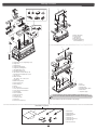
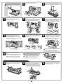
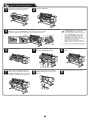
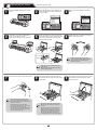
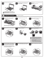
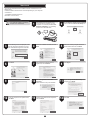
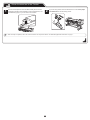
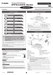
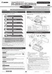
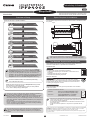
Introductory Information
ENG
Setup Guide
Read this manual before attempting to operate the printer.
Keep this manual in a handy location for future reference.
Introduction
Space Required for Installation
Overview of Setup
These are the steps in printer installation.
An area that is larger than the dimensions shown below is needed to install
the printer.
Attach the Media Take-up Unit (P.5)
(P.6)
Width and depth
OO
Attach the Output Stacker
OO
(P.3)
OO
Install the printer
OO
*
(P.3)
OO
Height
Assemble the Stand
(optional)
Install the Printheads
Load Paper
to Adjust the Printheads
OO
(P.9)
OO
OO
(P.10)
Caution
Install the Software and the
Electronic Manuals
OO
9
• When using the output stacker in the front ejection position, provide at
least 1400 mm (55 inches) of unobstructed space in front of the printer.
The Manuals Supplied with This Printer
(P.12)
After installing the printer as shown in this Setup Guide, refer to the
manuals for instructions on operation and maintenance.
Store Accessories in the Pocket (P.19)
Printed Manuals
Basic Guide
The Basic Guide contains the following information:
• Even if you do not use the printer driver, be sure to install Media
Configuration Tool from the provided User Software CD-ROM.
With Media Configuration Tool, the paper types that are available
in your area can be registered to the printer. For instructions on
installation, refer to "Install the Software and the Electronic Manuals"
on page 12. (In Windows, select Install Individual Software in the
Setup Menu window to install Media Configuration Tool only.)
• Loading paper, Replacing the consumables, Control Panel menus,
and others
• Troubleshooting tips and Error messages
• Preparations for transferring the printer
Electronic Manuals
• For more consistent colors, we recommend performing
color calibration after setup.
User's Guide
This guide describes advanced usage of the printer such as paper
saving tips, how to print a poster and banner with the supplied software
and print quality adjusting method, in addition to the basic instructions
for printing on roll paper or cut sheet.
Details for each step are given in this Setup Guide. Simply follow
the instructions to install the printer.
If an error message is displayed during setup or other problems
occur, refer to "Responding to Messages."
Paper Reference Guide
This guide describes about the types and specifications of the available
media on the printer.
MEMO
OO
(P.8)
OO
Mount the Ink Tanks
OO
&
Remove the Packaging Material (P.7)
To refer to the electronic manuals
• There are two ways to install the printer: tipping installation (installation by
four people) and lifting installation (installation by six people).
• Tipping installation (installation by four people) uses several special parts,
including the pieces attached to Stand casters to prevent slippage, the
black belts around the printer, and packaging material. Do not remove or cut
these parts. Otherwise, Tipping installation (installation by four people) is no
longer possible.
• Be sure to contact Canon dealer before transferring the printer to a new
location. Package the printer following the procedure of Lifting installation
and do not perform Tipping installation.
*
Q
T
5
7
0
8
8
V
2
*
Double-click the iPFxxxx Support desktop
icon. (iPFxxxx indicates the printer model.)
• Mac OS X :
Click the iPF Support icon in the Dock
(Launchpad in OS X v10.7 and later).
MEMO
• Some items are included with the printer but not described in this
manual. Keep these items in a safe place after setup because they are
used in various printing applications.
• For instructions on the included items not described in this manual, refer
to the User's Guide.
• A cable to connect the printer to a computer is not provided with the
printer.
• Canon, the Canon logo, and imagePROGRAF are trademarks or registered trademarks of CANON INC.
• Microsoft and Windows are trademarks of Microsoft Corporation, registered in the U.S. and other
countries.
• Macintosh is a trademark of Apple Inc., registered in the U.S. and other countries.
• All other trademarks or registered trademarks described in this Setup Guide are the property of their
respective owners.
• When relocating the printer, follow steps described in "Assemble the Stand"
to "Remove the Packaging Material" in reverse order to repackage the
printer. In this case, Tipping installation (installation by four people) is not
available.
QT5-7088-V2
• Windows :
1
©CANON INC. 2012
PRINTED IN CHINA
Package Contents
t
s
r
j
b
u
a
a
e
v
w
x
c
c
b
l
d
d
e
m
k
n
o
p
f h
q
a.
b.
c.
d.
e.
g
z
i
Bottom Stand Stay
Top Stand Stay
Left Stand Leg
Right Stand Leg
Packaging Material for
Printer Installation (2)
c
y
a.
b.
c.
d.
e.
f.
g.
h.
i.
j.
k.
Weight Flange 1 (2), Weight Flange 2 (2)
Weight Joint
Weight Roll (7)
Weight Roll Storage Box
Weight Flange Storage Box
Left Media Take-up Unit
Right Media Take-up Unit
Left Fastener for Media Take-up Unit
Right Fastener for Media Take-up Unit
Leg Cover (2)
Starter Ink Tanks
• BK, MBK, C, M, Y, PM, PC, GY
l. Printhead (2)
m. Media Take-up Sensor
n. M4 Hex Screws (35)
o. M8 Hex Bolts (8)
p. Wrench
q. Allen Wrench (2)
r. 3-inch paper core attachment #2
s. 3-inch paper core attachment #1
t. Documentation
u. Set of CD-ROMs
v. Ejection Support (6)
w. Cord Holder (2)
x. Accessory Pocket
y. Power Cord
z. Rewind 3-inch Adapter (2)
a
b
d
e
f
a.
b.
c.
d.
e.
f.
Printer
Roll Holder
Rewind Spool
Cardboard Stand Holder
Bottom Sheet
Adjustment paper
• The black belts are used on Tipping installation for the printer. Do not
remove or cut the belts. Otherwise, Tipping installation is no longer possible.
Other documentation may also be included in the package.
Basket BU-01 (optional)
a. b.
c.
d.
e.
a
f.
g.
b
2
h.
a.
b.
c.
d.
e.
f.
g.
h.
Basket Cloth
Basket Rod (2)
Middle Basket Rod
Basket Arm L
Basket Arm R
Rod Holder Adapter (2)
Rod Holder (2)
M4 Hex Screws (2)
Assemble the Stand
• Stand assembly requires two or more people
working on a flat floor. Assembling the Stand
Caution
alone may cause injury or accidental bending of
the Stand.
• Stand casters are locked at the time of factory
shipment. Do not release the lock until the
Stand has been fully assembled. In addition,
release the lock before moving the Stand.
Moving the Stand while the casters are locked
may scratch the floor or cause injury.
• Do not remove the pieces attached to the casters
to prevent slippage before the printer is mounted
on the Stand. Removing the pieces may cause
the Stand to slip, which may damage the printer
or bend the Stand. If the stand slips, the floor
may be scratched or injury may be caused.
1
Position the Left Stand Leg and Right
Stand Leg so that the markings on the
bottom are right-side up and can be read.
Insert the left side of the Bottom Stand
Stay into the side slot (a) of the Left
Stand Leg, and insert the right side of the
Bottom Stand Stay into the side slot (b)
of the Right Stand Leg.
2
Secure the Bottom Stand Stay to the
Left Stand Leg and Right Stand Leg
using four M4 hex screws on each side
by the Allen Wrench.
5
Secure the Top Stand Stay to the Left
Stand Leg and Right Stand Leg using
the four M8 hex bolts on each side by the
Wrench.
a
b
3
Hold one end of the Stand while a partner
holds the other end. At the same time,
rotate both ends to stand the Stand
upright.
4
Insert the left end of the Top Stand Stay into
the side hole (a) on the Left Stand Leg, and
insert the right end of the Top Stand Stay
into the side hole (b) on the Right Stand Leg,
pushing the stay in completely.
a
b
• Rotate both ends of the Stand
simultaneously when standing the Stand
upright. Rotating only one side before
the other may bend the Stand and cause
problems in assembly.
6
MEMO
Attach the Leg Cover to the Left Stand
Leg and Right Stand Leg. Insert the
protrusion (a) of the Leg Cover into the
groove (b) of the Top Stand Stay. Insert
the protrusion (c) of the Leg Cover into the
groove (d) of the Bottom Stand Stay.
a
b
b
d
7
• Insert the left end of the Top Stand Stay
first. The right end can only be pushed in to
a restricted position.
Secure the Leg Cover to the Left Stand
Leg and Right Stand Leg using one M4
hex screw on each side.
a
a
• On Tipping installation, do not remove the
pieces attached to the Stand casters to
Caution
prevent slippage yet.
a
d
c
c
Install the printer
There are two ways to install the printer. Follow either
procedure, depending on the number of people for
installing the printer.
• Tipping Installation: Requires four people
Follow the procedure starting at step 1 on page 3.
• Lifting Installation: Requires six people
Tipping installation: In the case of installation by four people
1
Remove the packaging material for use in
printer installation from the Stand box and
put the material against the pallet on both
ends, behind the printer.
Follow the procedure starting at step 12 on page 4.
• Tipping installation uses several special
parts, including the pieces attached
to Stand casters to prevent slippage,
the black belts around the printer, and
packaging material. Do not remove or cut
these parts. Otherwise, Tipping installation
is no longer possible.
3
2
Insert the hands in the holes on both ends of
the front surface of the bottom cardboard sheet.
While supporting the printer, tip the printer
backward 90 degrees to rest the printer on the
packaging material used in printer installation.
5
• Do not cut the black belts around the printer
until step 11. When the black belts are cut,
Tipping installation is no longer possible.
Remove the packaging material covering
the sections of the printer where the
Stand will be attached.
3
Remove the Sample Paper.
4
Turn the joints to pull out of the bottom
cardboard sheet on top of the pallet, and
then remove the cardboard stand holder.
6
Use scissors to cut openings in the plastic
covering as shown. Pull the covering apart
with both hands to expose the sections of the
printer where the Stand will be attached.
7
Remove the bottom cardboard sheet and
the pallet. Assemble the cardboard stand
holder as shown and put the holder to
the bottom side of the printer. Let the
side with round holes (a) face the printer.
a
8
Rest the Stand on its side on the
cardboard stand holder. Adjusting the
positions for attachment to the printer,
use an Allen Wrench to tighten four M4
screws on both sides, attaching the stand
securely to the printer.
9
Bend the front flap of the cardboard stand
holder forward as shown. Collapse the
holder and remove the holder from under
the stand.
10
Place the bottom sheet (a) under the
printer. Have four people hold the printer
and Stand on both ends, two people on
each end. As you support the printer, tip
it forward, pivoting it on the pieces of the
Stand to prevent it from slipping (b).
a
b
• Be careful to prevent the Stand from slipping.
MEMO • To avoid scratching the floor, be sure to
place the bottom sheet on the floor.
11
Remove the black belts (a) from the
printer.
Remove the packaging material (b), the
box (c) with the Rewind Spool inside, the
plastic covering (d), and the pieces (e)
attached to casters to prevent slippage.
• When cutting the black belts, be careful not
to let the belts fly away from the printer.
Caution
MEMO
• Remove the tape on the pieces to prevent
slippage by pulling the tape across the
pieces from above when peeling off.
c
b
b
a
e
d
e
a
Lifting installation: In the case of installation by six people
12
Remove the black belts from around the
printer and remove the top packaging
material.
13
While two people hold the carrying handles
under the printer on one end and lift the
printer a little, have a third person remove the
packaging material and the plastic covering
from under the printer. After the packaging
material has been removed, lower the printer.
4
14
Remove the packaging material and the
plastic covering from the other side of the
printer the same way.
15
16
With three people holding the carrying handles under the printer on both ends, lift the
printer.
• The weight of the main unit alone is approximately
164 kg (361.6 lb). Moving the printer requires at
Caution
least six people, three on either side. Be careful to
avoid back strain and other injuries.
• When moving the printer, firmly grasp the
carrying handles (a) under each side. Holding
the printer at other positions is dangerous
and cause injury and damage if the printer is
dropped.
Align the triangles on the back of the
printer and Stand when setting the
printer on the Stand. Secure the printer
and Stand firmly together using four M4
hex screws on each side by the Allen
Wrench.
a
Attach the Media Take-up Unit
1
2
Firmly secure the Left Fastener for Media Take-up Unit and
Right Fastener for Media Take-up Unit to the front (a) and
back (b) of the Top Stand Stay using four M4 hex screws on
each side by the Allen Wrench.
a
a
b
Hook up the hole (a) of the Left Media Take-up Unit with the protrusion
(b) of the Left Fastener for Media Take-up Unit, and hook up the
hole (c) of the Right Media Take-up Unit with the protrusion (d) of the
Right Fastener for Media Take-up Unit. Secure the Media Take-up
Units firmly by using three M4 hex screws (e) on each side by the Allen
Wrench in the sequence shown.
b
b
a
c
d
e
3
4
Pull up the cord of the Media Take-up
Sensor (a) through the hole (c) of the
Right Stand Leg. Put the Media Take-up
Sensor under the Bottom Stand Stay (b)
on the right.
b
c
a
MEMO
e
With the Media Take-up Sensor against the underside of the Bottom
Stand Stay and the Right Stand Leg, insert M4 hex screws in the three
holes (a) and slide the screws out of the way toward the narrow end of
the protruding holes. Insert M4 hex screws in the small holes (b) as well.
Use the Allen wrench to tighten all five M4 hex screws firmly in the
order shown, from (2) to (6).
b
a
• The Media Take-up Sensor remains
concealed in the Bottom Stand Stay.
a
b
b
a
a
5
Plug the Media Take-up Sensor cord
firmly and fully into the Right Media Takeup Unit to connect it.
6
Attach the cord holders (a) to the holes
of the Top Stand Stay. Bring the power
cord of the Right Media Take-up Unit to
the back of the printer and pass the cord
through the cord holders. After passing
the cord behind the holders, plug the cord
into the Power Supply Connector on the
back of the printer.
7
Load the left side of the Rewind Spool
on the Media Take-up Unit so that the
gear (a) on the right side of the Rewind
Spool meshes with the gear (b) of the
Right Media Take-up Unit.
OFF
ON
a
b
5
a
8
Attach the Output Stacker
1
9
Attach the Accessory Pocket to the Left Stand Leg.
Insert the Basket Arm R in the hole (a)
on the right side of the Bottom Stand
Stay. Insert the right side (b) of the middle
Basket Rod in the hole (c) of the Basket
Arm R.
Use the Allen Wrench to securely affix the M4 Hex Screws.
(BU-01 option)
2
After inserting the Basket Arm L in the
left side of the middle Basket Rod, push
in the arm fully into the hole on the left
side of the Bottom Stand Stay. Use one
M4 hex screw on the left and right sides
to firmly secure the Basket Arm R and
Basket Arm L.
3
While squeezing the Rod Holder in the
position indicated (a) with both hands,
push the holder into the Rod Holder
Adapter (b) until the holder clicks into
place. Attach the other Rod Holder to
the other Rod Holder Adapter the same
way.
a
b
a
b
c
4
Insert the Rod Holder Adapter into each
hole on the back of each Stand Leg.
5
Spread out the Output Stacker with white tag (a) of the Basket Cloth at the front on the right
side and the black cord (b) in the back.
Insert the Basket Rod (c) (in the middle of the Basket Cloth) in the hole (d) on the bottom of
the Rod Holder, and thread the black cord from the back through the hook (e) on the top of the
Rod Holder.
e
e
c
c
c
b
b
d
c
a
6
Check how the Basket Cloth is arranged.
(1) Pull out the Basket Cloth with the
edge facing out. Bringing the edge of
the Basket Cloth inside may prevent
paper ejection.
(2) If the Basket Cloth is inside as shown,
pull the cloth outside. Check the cloth
on each side.
7
Attach the Basket Rod (at the front of
the Output Stacker) to the tips (a) of the
Basket Arm L and Basket Arm R.
d
8
Pull the Basket Rod (a) (at the front of
the Output Stacker) all the way out and
lift the rod to lock the rod in place.
a
a
6
Remove the Packaging Material
1
Remove the tape and other packaging
material used to secure the printer.
3
Use the Allen Wrench to loosen the Belt Stopper screw (a) and remove the screw from the Belt
Stopper. Unscrew the Belt Stopper to the left and remove the stopper.
Pull the carriage spacer (b) in the direction of the arrow to remove it.
2
Open the Top Cover.
MEMO
a
• The Belt Stopper, screw, carriage spacer,
and Allen Wrench are needed when
moving the printer to another location later.
Keep the Belt Stopper, screw, carriage
spacer, and Allen Wrench which have
been removed. Neglecting to attach the
Belt Stopper and carriage spacer may
cause damage to the printer when moving
the printer to another location.
• After opening the Top Cover, Cleaning
Brush is stored on the right. Take out the
brush when cleaning inside the Top Cover.
b
4
Lift the Ejection Guide.
5
Attach the six Ejection Supports (a) on
the back of the Ejection Guide.
6
Close the Ejection Guide and Top
Cover.
9
Plug the power cord into the outlet.
a
7
When lowering the Ejection Guide (a),
lower it slowly. If you lower it vigorously,
the Ejection Supports (b) may touch the
roll paper and scratch the printing surface.
a
8
Plug the power cord into the Power
Supply Connector on the back of the
printer.
b
7
Mount the Ink Tanks
1
Press the Power button to turn on the
printer.
Mount the eight ink tanks.
2
When the following screen appears, use
the ▲ and ▼ keys to select a language
and press OK.
Language
3
Select your local time zone and press
OK.
Time Zone
㪈㪆㪉
4
Instructions on ink tank installation are
shown on the display screen.
Open the ink tank covers as instructed.
5
㪈㪆㪌
0:London (GMT)
+1:Paris,Rome
+2:Athens,Cairo
+3:Moscow
+4:Eerevan,Baku
English
ᣣᧄ⺆
Français
Italiano
Deutsch
Raise the stopper (a) of the ink tank lock
lever for the color you are mounting. After
raising the ink tank lock lever as far as
possible, pull it forward.
6
Shake each ink tank gently 7 to 8 times
before opening its pouch.
B
BK
BK
R
R
G
B
G
B
• Failure to shake the ink tanks may
result in reduced print quality because
ink ingredients have settled on the
bottom of the tank.
BK
R
G
a
B
• Press down on the ink tank lock lever
until it locks.
• Make sure the ink tank lock lever stays
in the locked position.
7
Open the pouch and remove the ink tank.
8
Orient the ink tanks and mount them in
the holders with ink holes down as shown
in the figure.
9
After raising the ink tank lock lever as far
as possible, press it back down until it
clicks into place.
B
BK
BK
R
R
G
B
• Never touch the ink holes or metal
contacts. Touching these parts may
cause stains, damage the ink tank, and
affect print quality.
• Avoid dropping the ink tank after
removing it from the pouch. Otherwise,
ink may leak and cause stains.
• Do not remove ink tanks to shake them
after they have been mounted. Doing
so may cause ink to spill.
• An ink tank cannot be mounted in the
holder if it is not oriented correctly for
the color.
• Do not try to force an ink tank into the
holder if it does not go in normally.
Check the color indicated on the label
affixed to the ink tank lock lever and
the ink tank orientation, and then try
mounting the tank into the holder again.
8
G
10
11
Make sure the ink lamp lights red.
Check that the ink lamp is alight, and then
push the ink tank more strongly until is
touches the base.
12
Repeat steps 5 to 11 to mount each of the
ink tanks.
Close the ink tank covers.
BK
R
BK
G
R
B
G
B
• If the ink lamp does not light, repeat
steps 5, 8, and 9.
Install the Printheads
1
Install both printheads.
When the display screen shows Open
Upper Cover, open the top cover.
2
Lift the carriage cover to open it fully.
3
Pull the printhead fixer lever forward all
the way to open it completely.
5
Hold the printhead by the grips (a) as you
remove it from the pouch.
6
Remove the orange protective part (a).
Remove the other orange protective part
(b) while holding the grip (c).
Instructions on printhead installation are
shown on the display screen.
4
Lift the printhead fixer cover to open it
fully.
b
c
a
a
a
• Never touch the parts covered by the
protective parts. Doing so may damage
the printhead and affect printing quality.
• The printhead contains ink, so be
careful not to spill it once the protective
parts are removed.
• Do not reattach the protective parts
after removing them. Dispose of these
materials according to local regulations.
.
7
Insert the printhead into the carriage (b)
with the ink holes (a) up and facing the
front of the printer as shown in the figure.
Carefully push the printhead firmly into
the carriage (b), ensuring that the parts
that were covered by the protective parts
do not touch the carriage (b).
8
Pull the printhead fixer cover down toward
the front to lock the printhead in place.
a
b
9
9
Push the printhead fixer lever all the way
back.
10
Repeat steps 3 to 9 to install the second
printhead set.
11
12
Pull the carriage cover forward.
Close the top cover.
Load Paper to Adjust the Printheads
Load the provided sample paper and adjust the Printheads.
1
Select type of paper for printhead adj.
is shown on the display screen. Use the
▲ and ▼ keys to select Roll Paper and
then press OK.
2
4
Raise the holder stopper lever (a) from the shaft side to unlock the
stopper. While holding the holder stopper in the position in the figure
indicated by (b), remove the holder stopper from the roll holder.
Open the top cover and raise the ejection
guide.
5
3
Remove the roll holder from the printer.
With the leading edge of the roll of paper towards the front as shown
in the figure, insert the roll holder from the right side of the roll of
paper. Insert the roll holder all the way until the paper is touching the
flange (a) of the roll holder.
a
b
a
• Insert the roll holder as far as it will go so there is no gap between
the paper and the roll holder flange. A gap can cause the paper to
feed irregularly.
• Do not place a roll of paper on a desk or other flat surface where it
may roll off. A falling paper roll creates the risk of personal injury.
• Do not allow the roll holder to be subjected to strong impact when
loading a roll of paper. Strong impact can damage the roll holder.
• We recommend wearing clean cotton gloves when handling rolls of
paper to protect the printable surface.
6
7
As shown in the figure, slide the holder stopper onto the roll holder
from the left. Holding the holder stopper at the position in the figure
marked (b), press until the holder stopper flange (a) is securely in
contact with the paper. Lower the holder stopper lever (c) to the shaft
side to lock it.
b
b
c
With the side of the roll holder with the white gear facing the same
direction as the roll holder slot with the white gear, set the roll holder
shaft (a) into the left and right guide grooves (b) of the roll holder
slots. Allow the shaft to slide into the guides as far as possible.
a
a
a
b
• When setting the shaft into the guides, take care so the roll of paper
does not fall and created the risk of personal injury.
• Be careful to not pinch your fingers between the shaft of the roll
holder shaft (a) and the guide grooves (b) when loading a roll of
paper.
• Insert the roll holder as far as it will go so there is no gap between
the paper and the roll holder flange. A gap can cause the paper to
feed irregularly.
• Remove all wrinkles and curls from the paper, if any, before loading
it.
10
8
Pull out the paper so it is even on both
sides and insert it into the feed slot (b),
and feed it until it contacts the paper
retainer (a).
The paper feeds automatically until it contacts the
paper retainer.
9
• Take care to avoid soiling the printing
surface when removing rolls of paper. A
soiled printing surface can affect printing
quality.
• Remove all wrinkles and curls from the
paper, if any, before loading it.
• When loading paper, make sure there is no
gap between the right side of the roll and
the roll holder.
a
Lower the ejection guide.
Lower the ejection guide carefully, taking
care that the ejection supports (a) do not
touch the paper.
b
a
b
10
While holding the leading edge of the
paper roll, raise the release lever.
11
Holding the leading edge of the paper with
both hands, gently pull it to the ejection
guide (a) as you ensure that the left and
right sides remain even and that the right
edge of the paper remains parallel with
the orange paper alignment line (b). Next,
lower the release lever.
12
Close the top cover.
b
a
After a roll of paper is loaded, the display
screen automatically display a paper type
selection menu and the printer beeps.
• Be sure to perform steps 10 and 11. If paper cannot feed straight or becomes curled, it may rub
against the print head or be jammed.
• Do not pull paper in an attempt to force it to align with the paper alignment line (b). Doing so may
cause the paper to not feed straight.
13
The screen for selecting the paper type
is shown on the display screen. Press ▲
or ▼ to select the type of paper loaded in
the printer.
Select Coated Paper and then press OK.
Then from the menu that appears, select
HW Coated and then press OK.
14
MEMO
Paper begins feeding.
MEMO
MEMO
• If Paper loaded crooked. appears on
the display screen, refer to steps 10 and
11 to reload the roll of paper.
If the error occurs again after you reload
the paper, remove the roll holder from
the printer and check to make sure that
the roll of paper is in close contact with
the roll holder flange as described in
step 5.
Once feeding the paper is finished, the
printer automatically starts charging
the system with ink and adjusting the
printhead. Charging the system with ink
and adjusting the printhead for the first
time takes about 41 minutes.
Install the printer driver and electronic
manuals on your computer while the
printer is working. (See "Install the
Software and the Electronic Manuals" on
page 12)
• Charging the system with ink fills the
system between the ink tanks and
printheads. In addition, cleaning is
performed to keep the printer in optimal
condition. This may cause the remaining
ink indicator and maintenance cartridge
capacity indicator to drop to about 80 %
(the remaining ink indicator may drop to
about 40 % for the starter ink tank), but
this is not a problem with the printer.
When printhead adjustment is finished,
Ready appears on the display screen.
• After you have finished setting up the printer and installing the software and electronic manuals, we recommend performing color calibration. Color
calibration compensates for changes in color from individual variation and aged deterioration of the printer, ensuring better color consistency.
Perform color calibration using the provided Sample Paper, which is compatible with this process. For information on other compatible paper, refer
to the Paper Reference Guide.
(settings/adj. tab) and select Adjust Printer - Calibration - Auto Adjust.
During color calibration, on the control panel's display screen, open
The process of color calibration takes about 10 minutes.
• If you use the color calibration for color adjustment, it is useful to set the function to notify the execution period (Prompt Execution). For details of
the function, refer to "Using Color Calibration for Color Adjustment" in User's Guide.
11
Install the Software and the Electronic Manuals
Windows
You can print from Windows via USB or TCP/IP (network) connections.
The installation procedure varies depending on how your printer is connected. Install the software and
the electronic manuals by following instructions below.
If you connect the printer with a USB cable, refer to "For USB connections" on page 12.
If you connect the printer with TCP/IP (network), refer to "For TCP/IP (network) connections" on page
14.
MEMO
The following screen may be displayed
during installation depending on the
security settings of your computer.
• Select Deactivate the block and click
Next.
• Installation requires administrative rights (such as those of Administrator). Be sure to log on using
an account with administrative rights before installation.
<Compatible Operating Systems>
32-bit: Windows 7, Windows Vista, Windows Server 2003 R2, Windows Server 2003, Windows XP
64-bit: Windows 7, Windows Vista, Windows Server 2008 R2, Windows Server 2008, Windows
Server 2003 R2, Windows Server 2003
MEMO
• For the Windows OS, use the latest version of Service Pack.
For USB connections
Install the software
• Use a USB cable that conforms to the
Hi-Speed USB specification.
• Connect the USB cable to the printer
according to the on-screen instructions
during installation of the printer driver.
If you connect the USB cable before
installing the printer driver, the printer
driver may not be installed correctly.
1
After making sure the printer is not
connected to the computer, turn the
computer on. Insert the provided User
Software CD-ROM for your operating
system in the CD-ROM drive.
2
MEMO
3
6
Select the software to install in the
Installation List window, and then click
Next.
Point the mouse pointer at a software
name to display a summary of the
software.
If you can agree Extended Survey
Program, click Agree.
In the Setup Menu window, click Install
Printer Driver.
• To choose a different language, click
Language.
4
In the Select Country or Region of Use
window, select the country or region of
use and click Next.
5
After reading the license agreement, click
Yes.
7
If you can respond to the questionnaire,
click Next.
8
Confirm your questionnaire responses,
and click Next.
12
9
In the Printer Selection window, select
The printer is connected directly to a
computer and click Next.
10
In the Printer Installation dialog box,
select Install with USB Connection, and
click Next.
11
MEMO
12
After reviewing the installation results in
the Complete Installation window, click
Next.
13
When the following dialog box is
displayed, make sure the printer is on and
use the USB cable to connect the printer
to the computer.
• If a warning message is displayed, click
Retry to try again.
In the Finish window, select Restart my
computer now and click Restart.
• Be careful not to insert the USB cable
into the LAN port.
Install the electronic manuals
14
When you restart the computer, the
software settings are enabled. The
software installation is now completed.
An iPFxxxx Support desktop icon
is created after installation. (iPFxxxx
represents the printer model.)
15
When the Install User Manual dialog
box is displayed, insert the provided User
Manuals CD-ROM in the CD-ROM drive
and click Next.
16
Click Next.
Next, install the electronic manuals.
17
After reading the software license
agreement, select I accept the terms of
the license agreement, and then click
Next.
18
Click Install.
The installation process begins.
19
After installation is completed, click
Finish.
The electronic manuals installation is now
completed.
20
Double-click the iPFxxxx Support
desktop icon.
21
When clicking the User's Manual button,
the User's Guide will be opened and
clicking the Paper Reference Guide
button, the Paper Reference Guide will be
opened.
13
For TCP/IP (network) connections
Install the software
• If the printer is already connected to
the network, confirm the IP address
assigned to the printer. Ask your
network administrator for further
information.
1
MEMO
Use the LAN cable to connect the LAN port
on the back of the printer to the hub port.
If the printer is already connected to the
network, proceed to step 2.
• If the printer is on, the Link indicator
under the LAN port lights.
1000Base-T
connection
100Base-TX
connection
10Base-T
connection
4
6
In the Printer Selection window, select
The printer is connected to computers
in a network and click Next.
5
The top and bottom LEDs
light.
The LED on the bottom
lights green.
The LED on the top lights
orange.
When searching the available printer on
the network
After reading the precautions in the
Getting Ready window, select Find
available printers in the network and
click Next.
Proceed to step 6.
When searching the available printer on the network
Available printers are listed in the Search Results window.
Select a printer from the list on either their IPv4 Devices or IPv6 Devices
tabs and click Next.
MEMO
2
3
Make sure the printer is on.
Turn the computer on and insert the
provided User Software CD-ROM for
your operating system in the CD-ROM
drive.
Perform procedures of steps 2-8 on page
12.
When entering the printer's IP address
manually
After reading the precautions in the Getting
Ready window, select Specify the IP
address of available printers in the
network and click Next.
Proceed to step 8.
• The IPv6 Devices tab is displayed in Windows 7, Windows Vista,
Windows Server 2008 R2, and Windows Server 2008.
• If the printer you want to use is not displayed in the list on the IPv6
Devices tab, connect via IPv4 instead.
• If the printer you want to use is not displayed in the list of printers on
the IPv4 Devices tab, refer to "When the printer cannot be found on
the network" on page 15 to setup and configure an IP address for the
printer.
Select the printer with the IP Address Status is Available, and then click
Next to start installation.
Proceed to step 9 in this case.
7
When searching the available printer on the network
In the Method of Configuring IP Addresses window, enter the IP
address in Configure manually, under Method of Configuring IP
Addresses. Click Install to start the installation process. Also enter your
preferred name for the printer in Device Name and the installation location
in Printer Location under Information About Printer to Configure, as
desired.
The installation process begins.
Proceed to step 9.
14
• If you use a DHCP server for automatic assignment of the printer's
IP address, printing may no longer be possible after the printer is
turned off and on. This is because a different IP address has been
assigned. When using DHCP server functions, consult your network
administrator and configure the settings in one of the following ways:
• Configure the setting for dynamic DNS updating
In the printer menu, either set DNS Dync update to On, or activate
the setting Enable DNS Dynamic Update in RemoteUI.
(→"Menu Settings", User's Guide)
(→"Configuring the Printer's TCP/IP Network Settings", User's
Guide)
• Configure the setting for assignment of the same IP address each
time the printer starts up
8
When entering the printer's IP address manually
In the IP Address Specification window,
select either IPv4 Address or IPv6
Address to enter the printer's IP address
and click Install.
The installation process begins.
• Ask your network administrator for the
IP address, as needed.
MEMO
9
After reviewing the installation results in
the Complete Installation window, click
Next.
• IPv6 Address is displayed in Windows
7, Windows Vista, Windows Server
2008 R2, and Windows Server 2008.
Install the electronic manuals
10
In the Finish window, select Restart my
computer now and click Restart.
11
When you restart the computer, the
software settings are enabled. The
software installation is now completed.
An iPFxxxx Support desktop icon
is created after installation. (iPFxxxx
represents the printer model.)
12
Next, follow steps 15-21 on page 13 to
Install the electronic manuals
When the printer cannot be found on the network
When ink fills the system for the first time, after
printhead adjustment is finished, specify the IP
address on the printer's control panel.
No Paper Loaded
OK:Setting/Adj. Menu
Maint. cart.
Remaining Amount
㪈㪇㪇㩼
MEMO
1.Select IPv4 and press OK.
2.Select IPv4 Settings and press OK.
3.Select IP Address and press OK.
4.Enter the IP address.
7
In the Search Results window, select
Specify the IP address of available
printers in the network and click Next.
When the IP Address Specifications
window appears, follow the instructions of
"When entering the printer's IP address
manually" in step 8 to 12 on page 15 to
complete the installation of the software
and electronic manuals.
MEMO
▲
4
How to enter IP addresses
1. Press the
and
keys to select a
field for inputting values.
2. Use the ▲ and ▼ keys to input values.
• Pressing ▲ increases the value by
one.
• Pressing ▼ decreases the value by
one.
• Holding down either the ▲ or ▼ keys
continually increases or decreases
the value.
3. Press OK once you have finished.
▲
• When ink fills the system for the first
time, do not operate the printer until
printhead adjustment is finished.
Enter the IP address. Navigate through
the following menus using the ▲ and ▼
keys on the control panel.
▲
1
On the tab selection screen of the control
panel, press the
and
keys to select
(settings/adj. tab) and press OK.
▲
If your printer cannot be found when connecting to
the network for the first time, setup an IP address
for the printer and then configure it on the printer.
• If the following screen appears, click
Retry and select Specify the IP
address of available printers in
the network on the next screen that
appears.
15
2
Use the ▲ and ▼ keys to select Interface
Setup and press OK.
3
Use the ▲ and ▼ keys to select TCP/IP
and press OK.
5
Press Menu.
6
Press OK on the registration confirmation
message that appears.
The IP address is set on the printer.
Next, restart installation of the printer
driver.
Macintosh
You can print from Macintosh via USB or network connections such as
Bonjour or IP.
Install the software and electronic manuals depending on your computer
environment.
<Compatible Operating Systems>
Mac OS X v10.5.8 to v10.7
Install the software
• If you install the software, log onto the
computer as an administrator.
2
On the desktop, double-click the CD-ROM
icon and then the iPF Printer Setup icon.
1
4
Select the software to install, and click
Next.
5
Select the country or region where the
printer will be used and click Next.
7
After reading the software license
agreement, click Continue.
8
After making sure the printer is not
connected to the computer, turn the
computer on. Insert the provided User
Software CD-ROM for your operating
system in the CD-ROM drive.
User Software
3
6
9
12
If the following screen is displayed, enter
the user name and password of a user
with administrative rights and click OK.
Click Next.
Click Continue.
If you can respond to the questionnaire,
click Next.
10
Exit other applications and click
Continue.
Items selected in step 4 are installed.
11
13
Confirm your questionnaire responses,
and click Next.
14
16
Click Agree.
If you can agree Extended Survey
Program, click Agree.
Click OK.
Connect the printer to a computer
15
Click Quit.
The software installation is now
completed. Next, connect the printer to
the computer.
16
Make sure that the printer is on, and then connect the printer to the computer or the network
with a cable.
• For USB connections
• For network connections
MEMO
• Be careful not to insert the USB cable into the LAN port.
Select the printer to setup
17
Click Next.
18
MEMO
20
MEMO
Click Finish.
• To register another printer, click
Continue Registration, and repeat
steps 17 to 19.
21
MEMO
Select the printer to setup and
click Next.
19
After entering your preferred name for
the printer in Printer Name and the
installation location in Location, click
Register.
• To register the printer by entering its IP
address, click Registering IP Address.
Enter the IP address of the desired
printer in IP Address and click Next.
22
Click OK.
The following screen is displayed and
paper information is updated. When the
paper information has been updated, the
screen is no longer displayed.
• If the same model of printer is already
registered on the computer, a screen is
displayed for printer selection. Select
the desired printer and click Next.
Install the electronic manuals
23
26
Next, install the electronic manuals.
Insert the provided User Manuals
CD-ROM in the CD-ROM drive.
Check the message and click Continue.
24
Double-click the iPFxxxx Manual
Installer icon on the CD-ROM. (iPFxxxx
represents the printer model.)
25
27
After reading the software license
agreement, click Continue.
28
17
Select the region where the printer will
be used and the language of the user
manual to install, and then click OK.
Click Agree.
29
Click Install.
30
After installation is completed, click Quit.
The electronic manuals installation is now
completed.
32
When clicking the User's Manual button,
the User's Guide will be opened and
clicking the Paper Reference Guide
button, the Paper Reference Guide will be
opened.
18
31
Click the iPF Support icon in the Dock
(Launchpad in OS X v10.7 and later).
Store Accessories in the Pocket
1
MEMO
2
Use the manual pocket to store the Basic Guide (which includes
descriptions of basic printer operations, routine maintenance, and
troubleshooting tips), so you can refer to it as needed.
If you are using a stand, store accessories such as the 3-inch paper
core attachment in the accessory pocket.
• When the setup is completed, refer to the various manuals to use the printer. Refer to "The Manuals Supplied with This Printer" on page 1.
19
Responding to Messages
Error messages may appear on the display screen of the control panel during printer installation. If so, it may not indicate a problem with the printer, and the issue may
be easily resolved. Common messages and the causes are listed here with corrective actions. To respond to error messages other than these, refer to the Basic Guide.
For details of operation procedure, refer to User's Guide installed in "Install the Software and the Electronic Manuals".
Message
Cause
Corrective Action
No ink tank loaded. Check ink tank.
There is no ink tank loaded.
Load or reload the ink tank.
(See steps 4-12 on pages 8-9)
Cannot recognize print head x.
The printhead is not installed.
Install the printhead.
(See steps 1-12 on pages 9-10)
Paper loaded crooked.
The loaded paper is crooked.
Reload the roll of paper. (See steps 10 and 11 on page 11)
If the error occurs again after you reload the roll of paper, remove
the roll holder from the printer and check to make sure that the
paper is in close contact with the roll holder flange. (See step 5 on
page 10)
No maintenance cartridge installed.
The maintenance cartridge is not connected.
Install the maintenance cartridge correctly.
Hardware error. xxxxxxxx-xxxx
(x represents a letter or number)
The belt stopper or the tape inside the top cover has not
been removed.
Turn off the power, open the top cover, and remove the tape and
the belt stopper, then turn the power on.
You may have encountered an error that cannot be
resolved.
Turn off the printer and wait at least three seconds before restoring
the power.
If the message appears again, write down the error code and
message, turn off the printer, and contact your Canon dealer for
assistance.
You may have encountered an error that cannot be
resolved.
Write down the error code and message, turn off the printer, and
contact your Canon dealer for assistance.
ERROR Exxx-xxxx
(x represents a letter or number)
20