1
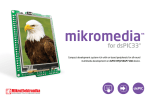
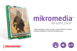
user's guide to mikrome ia board for ATmega Compact development system rich with on-board peripherals for all-round multimedia development on ATmega1280 device TO OUR VALUED CUSTOMERS I want to express my thanks to you for being interested in our products and for having confidence in Mikroelektronika. The primary aim of our company is to design and produce high quality electronic products and to constantly improve the performance thereof in order to better suit your needs. Nebojsa Matic General Manager The ATMEGA and Windows® logos and product names are trademarks of ATMEL® and Microsoft® in the U.S.A. and other countries. Table of Contents Introduction to mikromedia for ATmega 4 Programing with exernal programmer 16 Package Contains 5 4. Reset buttons 20 Key Features 6 5. Crystal oscillator 22 7 6. microSD Card Slot 23 8 7. Touch Screen 24 10 8. Audio Module 26 Key microcontroller features 10 9. USB UART communication 28 3. Programming the microcontroller 11 10. Accelerometer 30 Programming with mikroBootloader 12 11. Flash Memory 31 Identifying COM port 14 12. Pads 32 step 1 – Choosing COM port 14 13. Pinout 33 step 2 – Establishing connection 15 14. Dimensions 34 step 3 – Browse for .hex file 15 15. Mikromedia accessories 35 step 4 – Select .hex file 16 What’s next 36 step 4 – Uploading .hex file 16 step 6 – Progress bar 17 step 5 – Finish upload 17 System Specification 1. Power supply 2. ATmega1280 microcontroller Page 3 Introduction to mikromedia for ATmega The mikromedia for ATmega is a compact development system with lots of on-board peripherals which allow development of devices with multimedia contents. The central part of the system is the 8-bit ATmega1280 microcon troller. The mikromedia for ATmega features integrated modules such as stereo MP3 codec, TFT 320x240 touch screen display, accelerometer, USB connector, audio connector, MMC/SD card slot, 8 Mbit flash memory, 2x26 connection pads and other. It comes pre-programmed with USBUART bootloader, but can also be programmed with external AVR JTAGICE mkII. Mikromedia is compact and slim, and perfectly fits in the palm of the hand, which makes it convenient platform for mobile devices. Page 4 Package Contains 20122011 www.mikroe.com Copyright ©2011 Mikroelektronika. All rights reserved. Mikroelektronika, Mikroelektronika logo and other Mikroelektronika trademarks are the property of Mikroelektronika. All other tradmarks are the property of their respective owners. Unauthorised copying, hiring, renting, public performance and broadcasting of this DVD prohibited. 01 Damage resistant protective box 02 mikromedia for ATmega development system 04 mikromedia for ATmega user’s guide 05 mikromedia for ATmega schematic Page 5 03 DVD with documentation and examples 06 USB cable 10 Key Features 01 Connection Pads 02 TFT 320x240 display 03 USB MINI-B connector 04 CHARGE indication LED (RED) 05 Li-Polymer battery connector 06 3.5mm headphone connector 01 07 Power supply regulator 08 USB-UART IC 09 8MHz crystal oscillator 10 RESET button 11 VS1053 stereo audio codec 12 12.288MHz crystal oscillator 02 13 Atmel AVR ATmega 1280 device 14 Accelerometer 15 Serial 8Mbit Flash memory 16 15 microSD Card Slot 15 17 JTAG programmer connector 18 Power indication LED (GREEN) Page 6 04 05 03 06 System Specification 07 power supply Over a USB cable (5V DC) 08 09 power consumption 11 10 68 mA with erased MCU (when on-board modules are inactive) 12 13 board dimensions 8 x 6 cm (3.14 x 2.36 inch) 14 weight 15 17 ~46 g (0.10 lbs) 16 18 Page 7 1. Power supply 1. USB power supply Figure 1-1: Connecting USB power supply You can apply power supply to the board using MINI-B USB cable provided with the board. On-board voltage regulators will make sure that are avaibale the appropriate voltage levels to each part of the board. Power LED (GREEN) will indicate the presence of power supply. 2. Battery power supply You can also power the board using Li-Polymer battery, via on-board battery connector. On-board battery charger circuit MCP73832 enables you to charge the battery over USB connection. CHARGE LED (RED) will indicate battery charging. Led is off when battery is full. Charging current is ~250mA and charging voltage is 4.2V DC. Figure 1-2: Connecting Li-Polymer battery Page 8 DATA BUS VCC-SYS VCC-USB PMEG3010ER D1 C28 10nF VCC-BAT M1 DMP2160UW + - 1 2 3 4 5 R43 10K VCC-1.8 C29 R6 4K7 2.2uF R49 4K7 R34 4K7 1 2 3 Figure 1-3: Power supply schematics E10 VCC-1.8 10uF U3 Vin GND EN Vout ADJ R47 120K 5 4 AP7331-ADJ R46 22K R50 12K1 VCC-3.3 VCC-3.3 R35 10K 27 28 29 30 31 32 33 34 35 36 37 38 39 40 41 42 43 44 45 46 47 48 49 50 51 52 USB MINIB VCC-3.3 R39 4K7 HDR1 HDR2 VBUS DD+ ID GND CN1 BATT CONN VCC-BAT VSENSE VCC-SYS CN3 FP2 FERRITE 1 2 3 4 5 6 7 8 9 10 11 12 13 14 15 16 17 18 19 20 21 22 23 24 25 26 VCC-3.3 VCC-3.3 M1X26 M1X26 VCC-3.3 LD2 CHARGE VCC-3.3 VCC-BAT R36 10K STAT R37 10K Q4 BC846 Q5 BC846 R38 10K E5 10uF R45 1K VCC-SYS E7 C40 10uF 2.2uF 1 2 3 U5 STAT VSS VBAT PROG VDD 4 Charging Current approx. 250mA R44 3K9 LD1 POWER VCC-3.3 1 2K2 5 MCP73832 Page 9 VCC-SYS R26 3 E3 10uF REG1 Vin Vout GND E4 LD29080DT33 10uF 2 2. ATmega1280 microcontroller The mikromedia for ATmega development board comes with the AVR ATmega1280 microcontroller. This high-performance 8-bit microcontroller with its integrated modules and in combination with other on-board modules is ideal for multimedia applications. PORTS (A, B Key microcontroller features JTAG - Up to 16 MIPS Operation; - 128KB of Flash memory; TWI SPI FLASH XRAM ADC - 8KB of SRAM memory; TIMERS - 4KB of EEPROM - UART, SPI, TWI; , H, I, J, K, L) Analog Comparator - 8-bit architecture; - 86 I/O pins; Watchdog timer , C, D, E, F, G USART0 - ADC, Analog Comparator; - JTAG programming interface, etc. Page 10 USART1 EEPROM SRAM USART2 USART3 3. Programming the microcontroller Figure 3-1: ATmega1280 microcontroller The microcontroller can be programmed in two ways: 01 Via USB-UART mikroBootloader 02 Using external AVR JTAGICE mkII programmer Page 11 Programming with mikroBootloader mikroBootloader software You can program the microcontroller with UART bootloader which is preprogrammed into the device by default. To transfer .hex file from a PC to MCU you need bootloader software (mikroBootloader) which can be downloaded from: http://www.mikroe.com/eng/downloads/get/1822/ mikrobootloader_atmega1280_v210.zip After software is downloaded unzip it to desired location and start mikroBootloader software. Figure 3-2: mikroBootloader window 01 When you start mikroBootloader software, a window shown on Figure 3-2 should appear. Page 12 NOTE: Connect mikromedia for ATmega with a PC before starting mikroBootloader software Page 13 step 1 – Choosing COM port Identifying device COM port 02 01 03 01 Figure 3-3: Identifying COM port Figure 3-4: Selecting COM port 01 Click the Change Settings button 01 In Device Manager you can see which COM port is assigned to mikromedia (in this case COM32) 02 From drop down list select COM port which is used for communication with a PC (in this case COM32) 03 Click OK button Page 14 step 2 – Establishing connection step 3 – Browse for .hex file 01 01 Figure 3-5: Connecting mikromedia with mikroBootloader Figure 3-6: Browsing for .hex file 01 Reset mikromedia board and within 5s click the Connect button. If connected, caption on a button will be changed to “Disconnect”. 01 Click the Browse for HEX button and from pop-up window (figure 3-5) select .hex file which will be uploaded to MCU memory NOTE: Baud Rate is set to 56000bps by default Page 15 step 5 – Uploading .hex file step 4 – Select .hex file 01 02 01 Figure 3-7: Selecting HEX Figure 3-8: Begin uploading 01 To start .hex file uploading click the Begin uploading button 01 Select a .hex file via open dialog window 02 Click the Open button Page 16 step 6 – Progress bar step 7 – Finish upload 01 Figure 3-9: Progress bar Figure 3-10: Restarting MCU 01 You can monitor .hex file uploading via progress bar 01 Click the OK button after uploading is finished. Reset MCU and your mikromedia will start with new firmware. Page 17 Programing with external programmer NOTE: If bootloader program is accidently erased you can upload it again via AVR JTAGICE mkII programmer. Program mikroMedia for ATmega Bootloader Firmware.hex can be found under Firmware folder (page 12) Page 18 The microcontroller can be programmed with an external pro grammer (AVR JTAGICE mkII or other supported programer with JTAG interface). The external programmer is connected to the development system via pads marked with JTAG, Figure 3-11. In order to connect the external programmer to the development system, it is necessary to solder the 2x5 male headers provided with the product to JTAG pads Figure 3-11: mikroProg™ JTAG connector TCK TMS TDO TDI VCC-3.3 100 99 98 97 96 95 94 93 92 91 90 89 88 87 86 85 84 83 82 81 80 79 78 77 76 AVCC PB7 PH7 PG3/TOSC2 PG4/TOSCI1 RESET VCC GND XTAL2 XTAL1 PL0/ICP4 PL1/ICP5 PL2/T5 PL3/OC5A PL4/OC5B PL5/OC5C PL6 PL7 PD0/SCL PD1/SDA PD2/RXD1 PD3/TXD1 PD4/ICP1 PD5/XCK1 PD6/T1 PD7/T0 75 74 73 72 71 70 69 68 67 66 65 64 63 62 61 60 59 58 57 56 55 54 53 52 51 VCC-3.3 10K 10K 10K 10K ATmega1280 100pin TQFP AD3/PA3 AD4/PA4 AD5/PA5 AD6/PA6 AD7/PA7 ALE/PG2 PCINT15/PJ6 PCINT14/PJ5 PCINT13/PJ4 PCINT12/PJ3 XCK3/PJ2 TXD3/PJ1 RXD3/PJ0 GND VCC A15/PC7 A14/PC6 A13/PC5 A12/PC4 A11/PC3 A10/PC2 A9/PC1 A8/PC0 PG1 PG0 TCK TDO TMS TDI VCC-3.3 1 3 5 7 9 CN5 JTAG RESET# RESET# Figure 3-12: JTAG programmer connection schematics Page 19 R60 R61 R62 R63 PG5 PE0/RXD0 PE1/TXD0 PE2/XCK0 PE3/OC3A PE4/INT4 PE5/INT5 PE6/INT6 PE7/INT7 VCC GND PH0/RXD2 PH1/TXD2 PH2/XCK2 PH3/OC4A PH4/OC4B PH5/OC4C PH6/OC2B PB0/PCINT0 PB1/SCK PB2/MOSI PB3/MISO PB4/OC2A PB5/OC1A PB6/OC1B 26 27 28 29 30 31 32 33 34 35 36 37 38 39 40 41 42 43 44 45 46 47 48 49 50 1 2 3 4 5 6 7 8 9 10 11 12 13 14 15 16 17 18 19 20 21 22 23 24 25 AVCC GND AREF ADC0/PF0 ADC1/PF1 ADC2/PF2 ADC3/PF3 TCK/PF4 TMS/PF5 TDO/PF6 TDI/PF7 ADC8/PK0 ADC9/PK1 ADC10/PK2 ADC11/PK3 ADC12/PK4 ADC13/PK5 ADC14/PK6 ADC15/PK7 GND VCC PJ7 AD0/PA0 PA1 PA2 U1 2 4 6 8 10 4. Reset Buttons Board is equipped with two reset buttons. First is located at the back side of the board (Figure 4-1), and second one is at the top of front side (Figure 4-2). If you want to reset the circuit, press either of two buttons. It will generate low voltage level on microcontroller reset pin (input). In addition, a reset can be externally provided through pin 27 on side headers (Figure 4-3). Figure 4-1: Reset button located at the backside of the board Page 20 Figure 4-2: Frontal reset button AVCC VCC-3.3 VCC-3.3 100 99 98 97 96 95 94 93 92 91 90 89 88 87 86 85 84 83 82 81 80 79 78 77 76 R8 10K RST PG5 PE0/RXD0 PE1/TXD0 PE2/XCK0 PE3/OC3A PE4/INT4 PE5/INT5 PE6/INT6 PE7/INT7 VCC GND PH0/RXD2 PH1/TXD2 PH2/XCK2 PH3/OC4A PH4/OC4B PH5/OC4C PH6/OC2B PB0/PCINT0 PB1/SCK PB2/MOSI PB3/MISO PB4/OC2A PB5/OC1A PB6/OC1B PB7 PH7 PG3/TOSC2 PG4/TOSCI1 RESET VCC GND XTAL2 XTAL1 PL0/ICP4 PL1/ICP5 PL2/T5 PL3/OC5A PL4/OC5B PL5/OC5C PL6 PL7 PD0/SCL PD1/SDA PD2/RXD1 PD3/TXD1 PD4/ICP1 PD5/XCK1 PD6/T1 PD7/T0 ATmega1280 100pin TQFP AD3/PA3 AD4/PA4 AD5/PA5 AD6/PA6 AD7/PA7 ALE/PG2 PCINT15/PJ6 PCINT14/PJ5 PCINT13/PJ4 PCINT12/PJ3 XCK3/PJ2 TXD3/PJ1 RXD3/PJ0 GND VCC A15/PC7 A14/PC6 A13/PC5 A12/PC4 A11/PC3 A10/PC2 A9/PC1 A8/PC0 PG1 PG0 75 74 73 72 71 70 69 68 67 66 65 64 63 62 61 60 59 58 57 56 55 54 53 52 51 C3 100nF T1 T2 VCC-3.3 VCC-3.3 VCC-3.3 VCC-3.3 E8 10uF C5 100nF XTAL2 XTAL1 RST R7 100 X1 8MHz VCC-3.3 C2 22pF C6 100nF C7 100nF HDR2 RST 26 27 28 29 30 31 32 33 34 35 36 37 38 39 40 41 42 43 44 45 46 47 48 49 50 1 2 3 4 5 6 7 8 9 10 11 12 13 14 15 16 17 18 19 20 21 22 23 24 25 AVCC GND AREF ADC0/PF0 ADC1/PF1 ADC2/PF2 ADC3/PF3 TCK/PF4 TMS/PF5 TDO/PF6 TDI/PF7 ADC8/PK0 ADC9/PK1 ADC10/PK2 ADC11/PK3 ADC12/PK4 ADC13/PK5 ADC14/PK6 ADC15/PK7 GND VCC PJ7 AD0/PA0 PA1 PA2 U1 C1 22pF 27 28 29 30 31 32 33 34 35 36 37 38 39 40 41 42 43 44 45 46 47 48 49 50 51 52 M1X26 Figure 4-3: Reset circuit schematics Page 21 5. Crystal oscillator ATmega1280 is equipped with internal 128kHz RC oscillator that can provide base frequency. Board also contains 8MHz crystal oscillator (X1), which is the most optimal because chip is powered by 3.3V supply. Since chip does not have integrated PLL, maximum operating frequency is also 8MHz, which is just enough for your multimedia applications. AVCC 100 99 98 97 96 95 94 93 92 91 90 89 88 87 86 85 84 83 82 81 80 79 78 77 76 VCC-3.3 AVCC GND AREF ADC0/PF0 ADC1/PF1 ADC2/PF2 ADC3/PF3 TCK/PF4 TMS/PF5 TDO/PF6 TDI/PF7 ADC8/PK0 ADC9/PK1 ADC10/PK2 ADC11/PK3 ADC12/PK4 ADC13/PK5 ADC14/PK6 ADC15/PK7 GND VCC PJ7 AD0/PA0 PA1 PA2 U1 PG5 PE0/RXD0 PE1/TXD0 PE2/XCK0 PE3/OC3A PE4/INT4 PE5/INT5 PE6/INT6 PE7/INT7 VCC GND PH0/RXD2 PH1/TXD2 PH2/XCK2 PH3/OC4A PH4/OC4B PH5/OC4C PH6/OC2B PB0/PCINT0 PB1/SCK PB2/MOSI PB3/MISO PB4/OC2A PB5/OC1A PB6/OC1B PB7 PH7 PG3/TOSC2 PG4/TOSCI1 RESET VCC GND XTAL2 XTAL1 PL0/ICP4 PL1/ICP5 PL2/T5 PL3/OC5A PL4/OC5B PL5/OC5C PL6 PL7 PD0/SCL PD1/SDA PD2/RXD1 PD3/TXD1 PD4/ICP1 PD5/XCK1 PD6/T1 PD7/T0 ATmega1280 100pin TQFP AD3/PA3 AD4/PA4 AD5/PA5 AD6/PA6 AD7/PA7 ALE/PG2 PCINT15/PJ6 PCINT14/PJ5 PCINT13/PJ4 PCINT12/PJ3 XCK3/PJ2 TXD3/PJ1 RXD3/PJ0 GND VCC A15/PC7 A14/PC6 A13/PC5 A12/PC4 A11/PC3 A10/PC2 A9/PC1 A8/PC0 PG1 PG0 75 74 73 72 71 70 69 68 67 66 65 64 63 62 61 60 59 58 57 56 55 54 53 52 51 26 27 28 29 30 31 32 33 34 35 36 37 38 39 40 41 42 43 44 45 46 47 48 49 50 1 2 3 4 5 6 7 8 9 10 11 12 13 14 15 16 17 18 19 20 21 22 23 24 25 X1 C2 22pF 8MHz C1 22pF Figure 5-2: Crystal oscillator schematics Page 22 Figure 5-1: 8MHz crystal oscillator 6. microSD Card Slot Board contains microSD card slot for using microSD cards in your projects. It enables you to store large amounts of data externally, thus saving microcontroller memory. microSD cards use Serial Peripheral Interface (SPI) for communication with the microcontroller. Figure 6-1: microSD card slot module connection schematics VCC-3.3 100 99 98 97 96 95 94 93 92 91 90 89 88 87 86 85 84 83 82 81 80 79 78 77 76 75 74 73 72 71 70 69 68 67 66 65 64 63 62 61 60 59 58 57 56 55 54 53 52 51 VCC-MMC VCC-3.3 FP1 SD-CD# SD-CS# FERRITE C38 100nF VCC-MMC VCC-MMC R11 10K R10 10K CN4 R9 10K SD-CS# MOSI-PB2 SCK-PB1 MISO-PB3 SD-CD# E6 10uF R16 27 1 2 4 5 6 7 CD CS CS Din Din +3.3V +3.3V SCK SCK GND GND Dout Dout CD CD G R5 27 ATmega1280 100pin TQFP AD3/PA3 AD4/PA4 AD5/PA5 AD6/PA6 AD7/PA7 ALE/PG2 PCINT15/PJ6 PCINT14/PJ5 PCINT13/PJ4 PCINT12/PJ3 XCK3/PJ2 TXD3/PJ1 RXD3/PJ0 GND VCC A15/PC7 A14/PC6 A13/PC5 A12/PC4 A11/PC3 A10/PC2 A9/PC1 A8/PC0 PG1 PG0 PB7 PH7 PG3/TOSC2 PG4/TOSCI1 RESET VCC GND XTAL2 XTAL1 PL0/ICP4 PL1/ICP5 PL2/T5 PL3/OC5A PL4/OC5B PL5/OC5C PL6 PL7 PD0/SCL PD1/SDA PD2/RXD1 PD3/TXD1 PD4/ICP1 PD5/XCK1 PD6/T1 PD7/T0 R4 27 PG5 PE0/RXD0 PE1/TXD0 PE2/XCK0 PE3/OC3A PE4/INT4 PE5/INT5 PE6/INT6 PE7/INT7 VCC GND PH0/RXD2 PH1/TXD2 PH2/XCK2 PH3/OC4A PH4/OC4B PH5/OC4C PH6/OC2B PB0/PCINT0 PB1/SCK PB2/MOSI PB3/MISO PB4/OC2A PB5/OC1A PB6/OC1B 26 27 28 29 30 31 32 33 34 35 36 37 38 39 40 41 42 43 44 45 46 47 48 49 50 SCK-PB1 MOSI-PB2 MISO-PB3 AVCC GND AREF ADC0/PF0 ADC1/PF1 ADC2/PF2 ADC3/PF3 TCK/PF4 TMS/PF5 TDO/PF6 TDI/PF7 ADC8/PK0 ADC9/PK1 ADC10/PK2 ADC11/PK3 ADC12/PK4 ADC13/PK5 ADC14/PK6 ADC15/PK7 GND VCC PJ7 AD0/PA0 PA1 PA2 U1 1 2 3 4 5 6 7 8 9 10 11 12 13 14 15 16 17 18 19 20 21 22 23 24 25 GND G AVCC X1 C2 22pF 8MHz Figure 6-2: Inserting microSD card C1 22pF Page 23 7. Touch Screen The development system features a TFT 320x240 display covered with a resistive touch panel. Together they form a functional unit called a touch screen. It enables data to be entered and displayed at the same time. The TFT display is capable of showing data in 262.144 different colors. Figure 7-1: Touch Screen Page 24 TFT1 T-D0 T-D1 T-D2 VREF-1.8 LCD-XL LCD-YD VCC-3.3 VCC-SYS AVCC VCC-3.3 100 99 98 97 96 95 94 93 92 91 90 89 88 87 86 85 84 83 82 81 80 79 78 77 76 VCC-SYS AVCC GND AREF ADC0/PF0 ADC1/PF1 ADC2/PF2 ADC3/PF3 TCK/PF4 TMS/PF5 TDO/PF6 TDI/PF7 ADC8/PK0 ADC9/PK1 ADC10/PK2 ADC11/PK3 ADC12/PK4 ADC13/PK5 ADC14/PK6 ADC15/PK7 GND VCC PJ7 AD0/PA0 PA1 PA2 PB7 PH7 PG3/TOSC2 PG4/TOSCI1 RESET VCC GND XTAL2 XTAL1 PL0/ICP4 PL1/ICP5 PL2/T5 PL3/OC5A PL4/OC5B PL5/OC5C PL6 PL7 PD0/SCL PD1/SDA PD2/RXD1 PD3/TXD1 PD4/ICP1 PD5/XCK1 PD6/T1 PD7/T0 75 74 73 72 71 70 69 68 67 66 65 64 63 62 61 60 59 58 57 56 55 54 53 52 51 R40 12 E13 10uF T-D15 T-D14 T-D13 T-D12 T-D11 T-D10 T-D9 T-D8 VCC-3.3 VCC-3.3 R24 10K T-D15 T-D14 T-D13 T-D12 T-D11 T-D10 T-D9 T-D8 PMRD PMWR R25 10K LCD-RST LCD-CS# VCC-1.8 R41 1K VCC-3.3 10K R15 LCD-XR Q10 BC846 10K T-D7 T-D6 T-D5 T-D4 T-D3 T-D2 T-D1 T-D0 Q9 BC856 R58 R3 1K LCD-RST Q3 BC846 VCC-3.3 T-D3 T-D4 T-D5 T-D6 T-D7 LCD-RS LCD-RST LCD-CS# PMRD PMWR LCD-RS LCD-CS# VCC-1.8 Q8 BC856 R55 10K XTAL2 XTAL1 LCD-BLED ATmega1280 100pin TQFP AD3/PA3 AD4/PA4 AD5/PA5 AD6/PA6 AD7/PA7 ALE/PG2 PCINT15/PJ6 PCINT14/PJ5 PCINT13/PJ4 PCINT12/PJ3 XCK3/PJ2 TXD3/PJ1 RXD3/PJ0 GND VCC A15/PC7 A14/PC6 A13/PC5 A12/PC4 A11/PC3 A10/PC2 A9/PC1 A8/PC0 PG1 PG0 Q2 BC846 BAT43 26 27 28 29 30 31 32 33 34 35 36 37 38 39 40 41 42 43 44 45 46 47 48 49 50 DRIVEA DRIVEB PG5 PE0/RXD0 PE1/TXD0 PE2/XCK0 PE3/OC3A PE4/INT4 PE5/INT5 PE6/INT6 PE7/INT7 VCC GND PH0/RXD2 PH1/TXD2 PH2/XCK2 PH3/OC4A PH4/OC4B PH5/OC4C PH6/OC2B PB0/PCINT0 PB1/SCK PB2/MOSI PB3/MISO PB4/OC2A PB5/OC1A PB6/OC1B 1K D2 LCD-BLED U1 1 2 3 4 5 6 7 8 9 10 11 12 13 14 15 16 17 18 19 20 21 22 23 24 25 Q1 BC846 R23 LCD-YU LCD-XL X1 VCC-1.8 VREF-1.8 8MHz DRIVEA FP3 10K FERRITE C2 22pF R14 C1 22pF E11 10uF VCC-3.3 Q6 BC846 C21 100nF R42 100K LCD-YD R54 1K DRIVEB R56 10K Figure 7-2: Touch Screen connection schematics Page 25 Q7 BC846 C22 100nF R57 100K LCD-XR LCD-YD LCD-XL LCD-YU 1 2 3 4 5 6 7 8 9 10 11 12 13 14 15 16 17 18 19 20 21 22 23 24 25 26 27 28 29 30 31 32 33 34 35 36 37 38 39 40 41 42 43 44 45 46 47 LED-K LED-A1 LED-A2 LED-A3 LED-A4 IM0 IM1 IM2 IM3 RESET VSYNC HSYNC DOTCLK ENABLE DB17 DB16 DB15 DB14 DB13 DB12 DB11 DB10 DB9 DB8 DB7 DB6 DB5 DB4 DB3 DB2 DB1 DB0 SDO SDI RD WR/SCL RS CS FMARK VCC-IO VCC VCC-I GND XR YD XL YU MI0283QT2 8. Audio Module Figure 8-1: on-board VS1053 stereo audio codec mikromedia for ATmega features stereo audio codec VS1053. This module enables audio reproduction by using stereo headphones connected to the system via a 3.5mm connector CN2. All functions of this module are controlled by the microcontroller via Serial Peripheral Interface (SPI). Page 26 VCC-3.3 MP3-DCS 100 99 98 97 96 95 94 93 92 91 90 89 88 87 86 85 84 83 82 81 80 79 78 77 76 1 2 3 75 74 73 72 71 70 69 68 67 66 65 64 63 62 61 60 59 58 57 56 55 54 53 52 51 XTAL2 XTAL1 Vin GND EN Vout ADJ R47 120K 5 4 C4 100nF VCC-3.3 VCC-3.3 R46 22K C12 100nF C9 100nF C10 100nF C11 100nF VCC-3.3 VCC-3.3 VCC-3.3 C23 100nF C24 100nF C26 100nF C27 100nF MP3-DREQ VCC-1.8 R19 10K MP3-RST# VCC-3.3 MP3-CS# R33 VCC-3.3 E2 470 12 11 10 9 8 7 6 5 4 3 2 1 MP3-DCS 13 14 15 16 17 18 19 20 21 22 23 24 MP3-CS# XDCS/BSYNC IOVDD1 VC0 DGND1 XTAL0 XTAL1 IOVDD2 DGND2 DGND3 DGND4 XCS CVDD2 VS1053 GPIO5 RX TX SCLK SI SO CVDD3 XTEST GPIO0 GPIO1 GND GPIO4 12.288MHz C20 22pF 25 26 27 28 29 30 31 32 33 34 35 36 C19 22pF R32 C1 22pF R20 10K VCC-3.3 R21 10K R22 27 Figure 8-2: Audio module connection schematics Page 27 MISO-PB3 GPIO 8MHz E1 470 U2 LN2 AGND3 LEFT AVDD2 RCAP AVDD1 GBUF AGND2 AGND1 RIGHT AVDD0 AGND0 48 47 46 45 44 43 42 41 40 39 38 37 RIGHT GBUF 10uF L R17 100K R28 10 R29 10 CN2 PHONEJACK RIGHT C13 1uF R R18 100K C17 3.3nF LEFT LEFT 10uF C18 3.3nF MP3-RST# R2 10K X2 C2 22pF VCC-1.8 R50 12K1 R1 1M X1 10uF U3 GPIO7 GPIO6 GPIO3 GPIO2 DREQ CVDD1 IOVDD0 CVDD0 DGND0 XRESET MICN MCP/LN1 AVCC GND AREF ADC0/PF0 ADC1/PF1 ADC2/PF2 ADC3/PF3 TCK/PF4 TMS/PF5 TDO/PF6 TDI/PF7 ADC8/PK0 ADC9/PK1 ADC10/PK2 ADC11/PK3 ADC12/PK4 ADC13/PK5 ADC14/PK6 ADC15/PK7 GND VCC PJ7 AD0/PA0 PA1 PA2 PB7 PH7 PG3/TOSC2 PG4/TOSCI1 RESET VCC GND XTAL2 XTAL1 PL0/ICP4 PL1/ICP5 PL2/T5 PL3/OC5A PL4/OC5B PL5/OC5C PL6 PL7 PD0/SCL PD1/SDA PD2/RXD1 PD3/TXD1 PD4/ICP1 PD5/XCK1 PD6/T1 PD7/T0 R5 27 ATmega1280 100pin TQFP AD3/PA3 AD4/PA4 AD5/PA5 AD6/PA6 AD7/PA7 ALE/PG2 PCINT15/PJ6 PCINT14/PJ5 PCINT13/PJ4 PCINT12/PJ3 XCK3/PJ2 TXD3/PJ1 RXD3/PJ0 GND VCC A15/PC7 A14/PC6 A13/PC5 A12/PC4 A11/PC3 A10/PC2 A9/PC1 A8/PC0 PG1 PG0 VCC-1.8 VCC-1.8 AP7331-ADJ 26 27 28 29 30 31 32 33 34 35 36 37 38 39 40 41 42 43 44 45 46 47 48 49 50 R4 27 PG5 PE0/RXD0 PE1/TXD0 PE2/XCK0 PE3/OC3A PE4/INT4 PE5/INT5 PE6/INT6 PE7/INT7 VCC GND PH0/RXD2 PH1/TXD2 PH2/XCK2 PH3/OC4A PH4/OC4B PH5/OC4C PH6/OC2B PB0/PCINT0 PB1/SCK PB2/MOSI PB3/MISO PB4/OC2A PB5/OC1A PB6/OC1B MP3-CS# MP3-RST# MP3-DREQ SCK-PB1 MOSI-PB2 MISO-PB3 1 2 3 4 5 6 7 8 9 10 11 12 13 14 15 16 17 18 19 20 21 22 23 24 25 VCC-1.8 E10 2.2uF U1 VCC-1.8 VCC-1.8 C29 VCC-3.3 SCK-PB1 MOSI-PB2 AVCC R30 20 R31 20 C15 C16 R27 10 C14 10nF 10nF 47nF 9. USB-UART communication Figure 9-1: USB-UART communication Mikromedia contains USB MINI-B connector which is positioned next to the battery connector. FT232RL USB-UART IC enables you to implement UART serial communication functionality via USB cable, since ATmega1280 does not support USB protocol. Before connecting the board, make sure that you have FTDI drivers installed on your computer. Rx/Tx LED flashes when USB and controller communicate. Page 28 VCC-3.3 100 99 98 97 96 95 94 93 92 91 90 89 88 87 86 85 84 83 82 81 80 79 78 77 76 AVCC PG5 PE0/RXD0 PE1/TXD0 PE2/XCK0 PE3/OC3A PE4/INT4 PE5/INT5 PE6/INT6 PE7/INT7 VCC GND PH0/RXD2 PH1/TXD2 PH2/XCK2 PH3/OC4A PH4/OC4B PH5/OC4C PH6/OC2B PB0/PCINT0 PB1/SCK PB2/MOSI PB3/MISO PB4/OC2A PB5/OC1A PB6/OC1B PB7 PH7 PG3/TOSC2 PG4/TOSCI1 RESET VCC GND XTAL2 XTAL1 PL0/ICP4 PL1/ICP5 PL2/T5 PL3/OC5A PL4/OC5B PL5/OC5C PL6 PL7 PD0/SCL PD1/SDA PD2/RXD1 PD3/TXD1 PD4/ICP1 PD5/XCK1 PD6/T1 PD7/T0 ATmega1280 100pin TQFP AD3/PA3 AD4/PA4 AD5/PA5 AD6/PA6 AD7/PA7 ALE/PG2 PCINT15/PJ6 PCINT14/PJ5 PCINT13/PJ4 PCINT12/PJ3 XCK3/PJ2 TXD3/PJ1 RXD3/PJ0 GND VCC A15/PC7 A14/PC6 A13/PC5 A12/PC4 A11/PC3 A10/PC2 A9/PC1 A8/PC0 PG1 PG0 VCC-3.3 75 74 73 72 71 70 69 68 67 66 65 64 63 62 61 60 59 58 57 56 55 54 53 52 51 RX0-MCU TX0-MCU 1 2 3 4 5 6 7 8 9 10 11 12 13 14 VCC-3.3 U4 OSCO TXD OSCI DTR# TEST RTS# VCCIO AGND NC RXD CBUS0 RI# GND FT232RL CBUS1 GND NC DSR# VCC RESET# DCD# GND CTS# CBUS4 3V3OUT CBUS2 USBDM CBUS3 USBDP FT232RL USBDET XTAL2 XTAL1 26 27 28 29 30 31 32 33 34 35 36 37 38 39 40 41 42 43 44 45 46 47 48 49 50 1 2 3 4 5 6 7 8 9 10 11 12 13 14 15 16 17 18 19 20 21 22 23 24 25 AVCC GND AREF ADC0/PF0 ADC1/PF1 ADC2/PF2 ADC3/PF3 TCK/PF4 TMS/PF5 TDO/PF6 TDI/PF7 ADC8/PK0 ADC9/PK1 ADC10/PK2 ADC11/PK3 ADC12/PK4 ADC13/PK5 ADC14/PK6 ADC15/PK7 GND VCC PJ7 AD0/PA0 PA1 PA2 U1 USBDET RX0-MCU TX0-MCU X1 C2 22pF 8MHz C1 22pF Figure 9-2: USB-UART connection schematics Page 29 R53 220 28 27 26 25 24 23 22 21 20 19 18 17 16 15 LD3 RX/TX VCC-USB R51 4K7 C34 100nF C36 100nF R52 10K FP2 FERRITE R64 100 CN3 1 USBDM 2 USBDP 3 4 5 C28 10nF VBUS DD+ ID GND USB MINIB 10. Accelerometer On board ADXL345 accelerometer, among other features, can be used to measure acceleration in three axis: x, y, and z. The accelerometer function is defined by the user in the program loaded into the microcontroller. Communication between the accelerometer and the microcontroller is performed via the I2C interface. VCC-3.3 100 99 98 97 96 95 94 93 92 91 90 89 88 87 86 85 84 83 82 81 80 79 78 77 76 AVCC 26 27 28 29 30 31 32 33 34 35 36 37 38 39 40 41 42 43 44 45 46 47 48 49 50 Figure 10-1: Accelerometer connection schematics VCC-3.3 SDA ADD Res NC INT2 INT1 ADXL345 13 SDA-PD1 12 ACC ADDRESS 11 10 VCC-3.3 9 8 SCL-PD0 SDA-PD1 XTAL2 XTAL1 C2 22pF 3 VCC GND Res GND GND VCC 2 1 2 3 4 5 6 J1 VCC-3.3 X1 R13 10K R12 10K SCL-PD0 U9 Figure 10-2: Accelerometer module 14 VCC-3.3 SCL 75 74 73 72 71 70 69 68 67 66 65 64 63 62 61 60 59 58 57 56 55 54 53 52 51 1 PB7 PH7 PG3/TOSC2 PG4/TOSCI1 RESET VCC GND XTAL2 XTAL1 PL0/ICP4 PL1/ICP5 PL2/T5 PL3/OC5A PL4/OC5B PL5/OC5C PL6 PL7 PD0/SCL PD1/SDA PD2/RXD1 PD3/TXD1 PD4/ICP1 PD5/XCK1 PD6/T1 PD7/T0 ATmega1280 100pin TQFP AD3/PA3 AD4/PA4 AD5/PA5 AD6/PA6 AD7/PA7 ALE/PG2 PCINT15/PJ6 PCINT14/PJ5 PCINT13/PJ4 PCINT12/PJ3 XCK3/PJ2 TXD3/PJ1 RXD3/PJ0 GND VCC A15/PC7 A14/PC6 A13/PC5 A12/PC4 A11/PC3 A10/PC2 A9/PC1 A8/PC0 PG1 PG0 CS PG5 PE0/RXD0 PE1/TXD0 PE2/XCK0 PE3/OC3A PE4/INT4 PE5/INT5 PE6/INT6 PE7/INT7 VCC GND PH0/RXD2 PH1/TXD2 PH2/XCK2 PH3/OC4A PH4/OC4B PH5/OC4C PH6/OC2B PB0/PCINT0 PB1/SCK PB2/MOSI PB3/MISO PB4/OC2A PB5/OC1A PB6/OC1B 7 AVCC GND AREF ADC0/PF0 ADC1/PF1 ADC2/PF2 ADC3/PF3 TCK/PF4 TMS/PF5 TDO/PF6 TDI/PF7 ADC8/PK0 ADC9/PK1 ADC10/PK2 ADC11/PK3 ADC12/PK4 ADC13/PK5 ADC14/PK6 ADC15/PK7 GND VCC PJ7 AD0/PA0 PA1 PA2 U1 1 2 3 4 5 6 7 8 9 10 11 12 13 14 15 16 17 18 19 20 21 22 23 24 25 VCC-3.3 C33 100nF C32 100nF 8MHz C1 22pF Page 30 You can set the accelerometer address to 0 or 1 by re-soldering the SMD jumper (zero-ohm resistor) to the appropriate position. Jumper is placed in address 1 position by default. 11. Flash Memory VCC-3.3 100 99 98 97 96 95 94 93 92 91 90 89 88 87 86 85 84 83 82 81 80 79 78 77 76 AVCC PG5 PE0/RXD0 PE1/TXD0 PE2/XCK0 PE3/OC3A PE4/INT4 PE5/INT5 PE6/INT6 PE7/INT7 VCC GND PH0/RXD2 PH1/TXD2 PH2/XCK2 PH3/OC4A PH4/OC4B PH5/OC4C PH6/OC2B PB0/PCINT0 PB1/SCK PB2/MOSI PB3/MISO PB4/OC2A PB5/OC1A PB6/OC1B AD3/PA3 AD4/PA4 AD5/PA5 AD6/PA6 AD7/PA7 ALE/PG2 PCINT15/PJ6 PCINT14/PJ5 PCINT13/PJ4 PCINT12/PJ3 XCK3/PJ2 TXD3/PJ1 RXD3/PJ0 GND VCC A15/PC7 A14/PC6 A13/PC5 A12/PC4 A11/PC3 A10/PC2 A9/PC1 A8/PC0 PG1 PG0 75 74 73 72 71 70 69 68 67 66 65 64 63 62 61 60 59 58 57 56 55 54 53 52 51 Figure 11-2: Flash memory module VCC-3.3 VCC-3.3 R48 10K 26 27 28 29 30 31 32 33 34 35 36 37 38 39 40 41 42 43 44 45 46 47 48 49 50 PB7 PH7 PG3/TOSC2 PG4/TOSCI1 RESET VCC GND XTAL2 XTAL1 PL0/ICP4 PL1/ICP5 PL2/T5 PL3/OC5A PL4/OC5B PL5/OC5C PL6 PL7 PD0/SCL PD1/SDA PD2/RXD1 PD3/TXD1 PD4/ICP1 PD5/XCK1 PD6/T1 PD7/T0 ATmega1280 100pin TQFP R59 C37 VCC-3.3 FLASH-CS# MISO-PB3 FLASH-CS# R4 27 SCK-PB1 MOSI-PB2 MISO-PB3 R5 27 AVCC GND AREF ADC0/PF0 ADC1/PF1 ADC2/PF2 ADC3/PF3 TCK/PF4 TMS/PF5 TDO/PF6 TDI/PF7 ADC8/PK0 ADC9/PK1 ADC10/PK2 ADC11/PK3 ADC12/PK4 ADC13/PK5 ADC14/PK6 ADC15/PK7 GND VCC PJ7 AD0/PA0 PA1 PA2 U1 1 2 3 4 5 6 7 8 9 10 11 12 13 14 15 16 17 18 19 20 21 22 23 24 25 27 1 2 3 4 CS SDO WP GND M25P80 Figure 11-1: Flash memory module connection schematics Page 31 100nF U10 VCC HOLD SCK SDI 8 7 6 5 SCK-PB1 MOSI-PB2 Since multimedia applications are getting increasingly demanding, it is necessary to provide additional memory space to be used for storing more data. The flash memory module enables the microcontroller to use additional 8Mbit flash memory. It is connected to the microcontroller via the Serial Peripheral Interface (SPI). PK0 PK1 PK2 PK3 PK4 PK5 PK6 12. Pads VCC-3.3 100 99 98 97 96 95 94 93 92 91 90 89 88 87 86 85 84 83 82 81 80 79 78 77 76 AVCC L R PH3 PH4 PL3 PL4 PL0 PL1 PL2 PL5 PL6 PL7 PB5 PB6 PD4 PD5 PD6 PD7 RX1-PD2 TX1-PD3 SCL-PD0 SDA-PD1 VCC-3.3 PE4 PE5 PE6 PE7 PH0 PH1 PH2 PH3 PH4 PH5 PH6 R4 27 SCK-PB1 MOSI-PB2 MISO-PB3 PB5 R5 27 PB6 1 2 3 4 5 6 7 8 9 10 11 12 13 14 15 16 17 18 19 20 21 22 23 24 25 PG5 PE0/RXD0 PE1/TXD0 PE2/XCK0 PE3/OC3A PE4/INT4 PE5/INT5 PE6/INT6 PE7/INT7 VCC GND PH0/RXD2 PH1/TXD2 PH2/XCK2 PH3/OC4A PH4/OC4B PH5/OC4C PH6/OC2B PB0/PCINT0 PB1/SCK PB2/MOSI PB3/MISO PB4/OC2A PB5/OC1A PB6/OC1B ATmega1280 100pin TQFP AD3/PA3 AD4/PA4 AD5/PA5 AD6/PA6 AD7/PA7 ALE/PG2 PCINT15/PJ6 PCINT14/PJ5 PCINT13/PJ4 PCINT12/PJ3 XCK3/PJ2 TXD3/PJ1 RXD3/PJ0 GND VCC A15/PC7 A14/PC6 A13/PC5 A12/PC4 A11/PC3 A10/PC2 A9/PC1 A8/PC0 PG1 PG0 PB7 PH7 PG3/TOSC2 PG4/TOSCI1 RESET VCC GND XTAL2 XTAL1 PL0/ICP4 PL1/ICP5 PL2/T5 PL3/OC5A PL4/OC5B PL5/OC5C PL6 PL7 PD0/SCL PD1/SDA PD2/RXD1 PD3/TXD1 PD4/ICP1 PD5/XCK1 PD6/T1 PD7/T0 27 28 29 30 31 32 33 34 35 36 37 38 39 40 41 42 43 44 45 46 47 48 49 50 51 52 RST AVCC GND AREF ADC0/PF0 ADC1/PF1 ADC2/PF2 ADC3/PF3 TCK/PF4 TMS/PF5 TDO/PF6 TDI/PF7 ADC8/PK0 ADC9/PK1 ADC10/PK2 ADC11/PK3 ADC12/PK4 ADC13/PK5 ADC14/PK6 ADC15/PK7 GND VCC PJ7 AD0/PA0 PA1 PA2 U1 HDR2 VCC-SYS 75 74 73 72 71 70 69 68 67 66 65 64 63 62 61 60 59 58 57 56 55 54 53 52 51 M1X26 HDR1 PJ2 PJ1 PJ0 PK0 PK1 PK2 PK3 PK4 PK5 PK6 PE4 PE5 PE6 PE7 PJ0 PJ1 PJ2 PH0 PH1 PH2 PH5 PH6 SCK-PB1 MISO-PB3 MOSI-PB2 VCC-3.3 1 2 3 4 5 6 7 8 9 10 11 12 13 14 15 16 17 18 19 20 21 22 23 24 25 26 XTAL2 XTAL1 PL0 PL1 PL2 PL3 PL4 PL5 PL6 PL7 SCL-PD0 SDA-PD1 RX1-PD2 TX1-PD3 PD4 PD5 PD6 PD7 26 27 28 29 30 31 32 33 34 35 36 37 38 39 40 41 42 43 44 45 46 47 48 49 50 M1X26 X1 Pads HDR2 C2 22pF 8MHz C1 22pF Figure 12-1: Pads connecting schematics Pads HDR1 Most microcontroller pins are available for further connectivity via two 1x26 rows of connection pads on both sides of the mikromedia board. They are designed to match additional shields, such as Battery Boost shield, Gaming, PROTO shield and others. Pads with underlined silkscreen markings have multiple functions (see the complete schematics for more information). Page 32 13. Pinout System power supply Reference Ground Analog Lines Interrupt Lines Digital I/O lines SCK SDI SPI Lines SDO 3.3V power supply Reference Ground VSYS GND PK0 PK1 PK2 PK3 PK4 PK5 PK6 PE4 PE5 PE6 PE7 PJ0 PJ1 PJ2 PH0 PH1 PH2 PH5 PH6 PB1 PB3 PB2 3.3V GND RST GND L R PH3 PH4 PL3 PL4 PL0 PL1 PL2 PL5 PL6 PL7 PB5 PB6 PD4 PD5 PD6 PD7 PD2 PD3 PD0 PD1 3.3V GND Reset pin Reference Ground left ch. audio out right ch. PWM lines Digital I/O lines RX TX UART Lines SCL2 I2C Lines SDA2 3.3V power supply Reference Ground Pin functions Pin functions Digital lines Analog Lines Interrupt Lines SPI Lines Page 33 I2C Lines UART lines PWM lines 14. Dimensions 80.90 mm (3.18”) 73.01 mm (2.87”) 36.55 mm (1.44”) 50.27 mm (1.98”) 55.47 mm (2.18”) 5.08 mm (0.20”) 60.56 mm (2.38”) 69.85 mm (2.75”) 4.45 mm (0.17”) 2.54 mm (0.10”) Page 34 2.77 mm (0.11”) 15. mikromedia accessories We have prepared a set of extension boards pin-compatible with your mikromedia, which enable you to easily expand your board basic functionality. We call them mikromedia shields. But we also offer other accessories, such as Li-polymer battery, stacking headers, wire jumpers and more. 04 Gaming shield 01 Connect shield 02 BatteryBoost shield 03 PROTO shield 05 Li-Polimer battery 06 Wire Jumpers 07 Stacking headers Page 35 What’s next? You have now completed the journey through each and every feature of mikromedia for ATmega board. You got to know it’s modules and organization. Now you are ready to start using your new board. We are suggesting several steps which are probably the best way to begin. We invite you to join the users of mikromedia™ brand. You will find very useful projects and tutorials and can get help from a large ecosystem of users. Welcome! Compiler You still don’t have an appropriate compiler? Locate AVR® compiler that suits you best on the Product DVD provided with the package: DVD://download/eng/software/compilers/ Choose between mikroC™, mikroBasic™ and mikroPascal™ and download fully functional demo version, so you can begin building your first applications. Projects Once you have chosen your compiler, and since you already got the board, you are ready to start writing your first projects. Visual TFT software for rapid development of graphical user interfaces enables you to quickly create your GUI. It will automatically create necessary code which is compatible with mikroElektronika compilers. Visual TFT is rich with examples, which are an excellent starting point for your future projects. Just load the example, read well commented code, and see how it works on hardware. Visual TFT is also available on the Product DVD. Page 36 Notes: Page 37 Notes: Page 38 DISCLAIMER All the products owned by MikroElektronika are protected by copyright law and international copyright treaty. Therefore, this manual is to be treated as any other copyright material. No part of this manual, including product and software described herein, may be reproduced, stored in a retrieval system, translated or transmitted in any form or by any means, without the prior written permission of MikroElektronika. The manual PDF edition can be printed for private or local use, but not for distribution. Any modification of this manual is prohibited. MikroElektronika provides this manual ‘as is’ without warranty of any kind, either expressed or implied, including, but not limited to, the implied warranties or conditions of merchantability or fitness for a particular purpose. MikroElektronika shall assume no responsibility or liability for any errors, omissions and inaccuracies that may appear in this manual. In no event shall MikroElektronika, its directors, officers, employees or distributors be liable for any indirect, specific, incidental or consequential damages (including damages for loss of business profits and business information, business interruption or any other pecuniary loss) arising out of the use of this manual or product, even if MikroElektronika has been advised of the possibility of such damages. MikroElektronika reserves the right to change information contained in this manual at any time without prior notice, if necessary. HIGH RISK ACTIVITIES The products of MikroElektronika are not fault – tolerant nor designed, manufactured or intended for use or resale as on – line control equipment in hazardous environments requiring fail – safe performance, such as in the operation of nuclear facilities, aircraft navigation or communication systems, air traffic control, direct life support machines or weapons systems in which the failure of Software could lead directly to death, personal injury or severe physical or environmental damage (‘High Risk Activities’). MikroElektronika and its suppliers specifically disclaim any expressed or implied warranty of fitness for High Risk Activities. TRADEMARKS The MikroElektronika name and logo, the MikroElektronika logo, mikroC™, mikroBasic™, mikroPascal™, mikroProg™, EasyAVR6™, BIGAVR6™, AVRPLC16 v6™ and mikromedia™ are trademarks of MikroElektronika. All other trademarks mentioned herein are property of their respective companies. All other product and corporate names appearing in this manual may or may not be registered trademarks or copyrights of their respective companies, and are only used for identification or explanation and to the owners’ benefit, with no intent to infringe. Copyright © MikroElektronika, 2012, All Rights Reserved. Page 39 If you want to learn more about our products, please visit our website at www.mikroe.com If you are experiencing some problems with any of our products or just need additional information, please place your ticket at www.mikroe.com/esupport If you have any questions, comments or business proposals, do not hesitate to contact us at [email protected] mikromedia for ATMEGA Manual (Mini) ver. 1.00 0 100000 018798