1
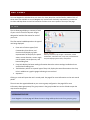
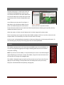
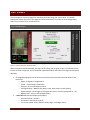
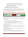
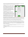
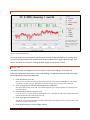
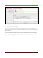
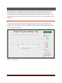
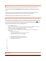
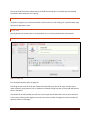
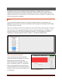
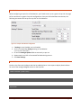
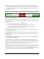
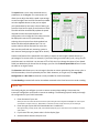
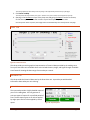
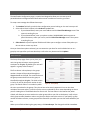
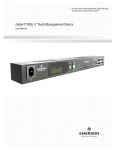
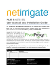
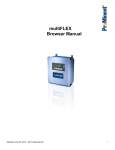
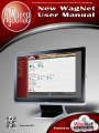
259 Dakota Ave South | PO Box 53 | Huron, SD 57350 | www.agsense.net | 605.352.8350 Introduction December 2012 Page 1 TABLE OF CONTENTS INTRODUCTION AVAILABILITY OF OLD WAGNET LIST OF NEW FEATURES SUMMARY OF MANUAL WE WOULD LIKE YOUR FEEDBACK 3 3 3 3 3 UNIT VIEWS LIST VIEW MAP VIEW SIDEBAR 4 4 5 5 UNIT PAGES FIELD COMMANDER CROP LINK WEATHER TRAC (CROP LINK) GRAIN TRAC (CROP LINK) TANK MONITOR (CROP LINK) PUMP CONTROL (CROP LINK) SOIL MOISTURE MONITOR (CROP LINK) AQUATRAC PRECISION LINK PIVOT POINT 6 6 13 16 18 19 20 20 20 21 22 ACCOUNT MANAGEMENT ACCOUNT INFORMATION ACCOUNT SETTINGS CHANGE YOUR PASSWORD NOTIFICATION CONFIGURATION GROUP SETUP 28 28 28 28 29 29 GETTING HELP KNOWLEDGE DATABASE INSTALLATION GUIDES CONTACT US TICKETS OVERVIEW 30 30 30 30 30 Introduction Page 2 INTRODUCTION AVAILABILITY OF OLD WAGNET LIST OF NEW FEATURES SUMMARY OF MANUAL WE WOULD LIKE YOUR FEEDBACK Introduction Page 3 UNIT VIEWS Our new WagNet site includes three unit views: List View, Map View, and the familiar sidebar. Each of these views was available on our old WagNet site, but has been drastically improved for our new site. List View and Map View can each be located in the View Units menu option at the top of the page. LIST VIEW The List View page displays a summary of each of your units as a series of dynamic images designed to load the information for each of your units. The information loaded depends on the type of unit being displayed: Pivot units of various types (Field Commanders, Pivot Points, and Precision Links) display a graphic Figure 1 - List View representation of the pivot, the power From top to bottom, left to right: a Pivot Point, a Field status, current direction, current angle, Commander, a Precision Link, a Crop Link, a Tank Monitor Crop Link displaying three tanks, an Aquatrac current speed, current pressure, and latest reading time. Crop Links display the latest reading information about the various analogs installed on them and the latest reading time. Tank Monitors, which are a special type of Crop Link, display the same information as the Crop Links in addition to a graphic gauge indicating its current level. Aquatracs … Clicking on a unit will open that unit’s control panel. See page 6 for more information on the unit control panels. The units are also organized based on your current group configuration. See page 29 for more information about group setup. The group names in the group header bars can be clicked to open the map view for that group. UPCOMING FEATURE Soon WagNet’s List View page will allow the user to drag and drop their units from group to group. Unit Views Page 4 MAP VIEW The Map View page is a radical new screen for viewing and managing groups of units at one time. Many new features have been added from our previous Map View to allow you to get a fast an accurate picture of what is happening in your fields. A new feature you may notice from Figure 2 Map View is the information bubble over the Figure 2 - Map View A pivot point and its information bubble pivot. This bubble displays the most need-toknow information about the unit and a few of the command buttons allowing you to quickly send any needed commands to your unit. Other than pivots, all other units will display their List View image and its power status. There are two ways you can get the information bubble to display. The first is to click on the unit in the Groups sidebar. The second way is to click on the unit itself in the map. On this screen, each group displays separately to decrease loading time and increase performance. To view another group, simply click on the group name in the Groups sidebar. SIDEBAR This sidebar represents the list of units that was available to you in our old website. It is a list of units organized by groups with images indicating what the units are and what any pivots are doing. Note: If you do not see this sidebar, it may be because your screen is not wide enough to support displaying it at all times. To open the sidebar, simply click the View Units item in the menu bar to the right of the WagNet logo. This sidebar is designed to give you quick and easy access to any of your units from any page you may be viewing. It also provides links to the Map View and to your Group Setup (for more detail about Group Setup, see page 29). Unit Views Figure 3 - Sidebar Page 5 UNIT PAGES The unit pages are a series of pages for controlling and monitoring your various units. This section explains the various parts of the unit pages for Field Commanders, Crop Links (of each configuration), Aqua Tracs, Precision Links, and Pivot Points. FIELD COMMANDER Figure 4 - Field Commander Information Panel When you open a Field Commander unit page, the first thing you are going to see is an information box, like the one seen in Figure 4 - Field Commander Information Panel, at the top of the page containing the following: An image displaying the current activity and status of the pivot with numerical details at the bottom of: o Angle – 0 degrees is straight North o Speed – in percentage of maximum o Pressure – the current water pressure o GPS signal status – WAAS is best, Basic is okay, None means no GPS reading o Signal strength – the strength of the signal your pivot is communicating with (0 – 31) o Battery level – 4.2V is a fully charged battery A Pivot Info tab with the following information: o Serial and version numbers o If and who it was shared to you by o The current power status, direction status, angle, and endgun status Unit Pages Page 6 o The timestamp of the most recent reading generated by the Field Commander o The amount of time the Field Commander has been on its current cycle o Information about the most recent 2 commands sent to the Field Commander o Information about upcoming timed commands o The most recent note entered in the notes tab A Timed Commands tab listing all currently set timed commands A Notes tab where you can enter various notes to yourself about the unit Below the information panel is a series of tabbed panels: CMD, Chart, Config, Readings, Report, CMD History, Tickets. The CMD tab displays various command controls you can use to control your Field Commander unit including Start/Stop/Change Direction commands, Endgun/Speed table controls, Run table controls, and the ability to request a reading. CMD TAB Figure 5 – Basic Field Commander Commands The Start and Stop commands can be used to send an immediate or timed command to start and stop the unit respectively based on the option chosen in the dropdown box to the right of the command. The available options are: Now – Immediately sends a start/stop command to the unit Once – Gives you the option to choose a specific date and time to start/stop the unit Always – Gives you the option to choose a specific time to start/stop the unit every day Clear – Clears all once/always timed start/stop commands The Start FWD and Start REV commands allow you to send an immediate start command to start the pivot in the direction of your choice. The Stop @ Angle command allows you to send a timed command to the Field Commander to stop the unit at a specified angle. You can also use the dropdown box to the immediate right of the command to clear the timed command. The Change Dir FWD and Change Dir REV commands can be used to send an immediate command to the unit to change its current direction. Also note that when the unit is powered off, all of these commands will be disabled until the unit is powered on. When the unit is on and idle, the stop commands will be disabled. When the unit is on and Unit Pages Page 7 moving, the start commands will be disabled. When the unit is moving forward, the Change Dir FWD command will be disabled and vice versa for the Change Dir REV command. The End Gun table allows you to adjust the angles at which the end gun on your pivot will run. There are three customizable tables that can be renamed and two tables called Always On and Always Off. In the customizable tables, once you have entered your preferred settings click Save & Send command to lock in those settings. Also click this command to lock in tables when switching between them. The Speed Table is much more advanced than its predecessor in old WagNet. This new version still allows you to adjust the table’s speed in percentage at various angles from 0 to 359. Now we have added an Inches Applied column so that you can adjust your speed tables by how many inches of water you want the Field Commander to apply to each section of field. The table will then automatically update the Figure 6 – End Gun & Speed tables and Misc. Commands speed required to match that value based on the configuration in the Config tab. This column can also be displayed in metric units (centimeters) by selecting the unit system from the dropdown box below the table name dropdown box. This unit system selection will be automatic for users who have set their preferred unit measuring system in their Account Settings page (see page 28 for details). Another new feature of the speed table is the ability to adjust the entire table’s Speed column by a percentage of its current value. For example, if you had a setting set to 40% duty cycle, raising it by 5% would increase it to 42 (which is an increase of 5% of 40). Also if you change the values of your Speed Table, but decide that you do not like the changes, you can click the Reset Speed Table button to reset the table to its original values. As of right now, the Large Table Configuration and Run Table commands will direct you to a page from old WagNet for these settings. The Get Reading command will send an immediate command to the Field Commander unit to send a reading. Unit Pages Page 8 CHART TAB Figure 7 - Field Commander Chart This tab provides you with a graphical representation of historical data provided by the readings sent from your Field Commander unit. Available chart series include Pressure, Angle, Signal Strength, and Battery. Available time frames for viewing this data range from one day to a month. CONFIG TAB The Config tab give you configure your unit to ensure accurate data readings. Please note that inaccurate configuration could result in inaccurate readings. The following steps will walk you through the configuration of your Field Commander. 1. Enter the name of your unit. What you enter here will be the name that shows up describing the unit throughout the WagNet site. A descriptive name about its location is best (ex. ‘Behind Barn’) to know at all times exactly which unit you are looking at. 2. Enter the type of pivot the Field Commander box is installed on. We support Valley, Lindsay, Reinke, T&L, and Lockwood specifically. If your Field Commander is not installed on one these, select ‘Other.’ 3. Selection which direction the pivot runs. If your unit runs in a circle, then this option should be set as such. A pivot that runs side to side is called a lateral pivot and you should choose which direction the pivot runs. 4. Enter the length of the pivot in feet. This number is used in several calculations involved in Speed Tables and reading generation; so, please make sure this number is as accurate as you can get it. 5. Enter the distance your pivot’s end gun reaches Unit Pages Page 9 This number is used in several calculations involved in Speed Tables and reading generation; so, please make sure this number is as accurate as you can get it. 6. (For circle pivots) Enter the minimum angle of the unit’s operation Remember that 0 degrees represents straight North. This number is used in several calculations involved in Speed Tables and reading generation; so, please make sure this number is as accurate as you can get it. 7. (For circle pivots) Enter the maximum angle of the unit’s operation Remember that 0 degrees represents straight North. This number is used in several calculations involved in Speed Tables and reading generation; so, please make sure this number is as accurate as you can get it. 8. Enter the time it takes for the pivot to complete one revolution at 100% duty cycle (speed). This number is used in several calculations involved in Speed Tables and reading generation; so, please make sure this number is as accurate as you can get it. 9. 10. 11. 12. Enter the type of pressure sensor being used. Enter the low pressure Enter the high pressure Enter the voltage at 0 PSI 0.5 volts is the correct normal value. 13. Enter the estimated flow in gallons per minute This number is used in several calculations involved in Speed Tables and reading generation; so, please make sure this number is as accurate as you can get it. 14. The External 1 and External 2 fields are set by AgSense, call 1-605-352-8350 for details. 15. Enter the conditions for speed and end gun usage. 16. Click Save Settings and then proceed to the instructions below to set your pivot’s GPS location. Now that you have your Field Commander configured to the correct settings, the next step is to set the GPS location on the map at the bottom of the Config tab. For circle pivots: 1. Enter the GPS coordinates of the center of your pivot in the text boxes provided for latitude and longitude. Coordinates must be entered in decimal degrees. 2. If you wish to adjust the zoom setting, feel free to do so. This setting adjusts the zoom level for the map image in the information panel at the top of the page. 3. Click Center on Map. A marker should appear on the map 4. In the map provided, if the marker is not exactly over the center location of your pivot, you can fix it by clicking on the map where the center should be. 5. Click Save Settings again to save the GPS coordinates. Unit Pages Page 10 For lateral pivots: 1. Enter the GPS coordinates of the center of your pivot in the text boxes provided for latitude and longitude. Coordinates must be entered in decimal degrees. 2. If you wish to adjust the zoom setting, feel free to do so. This setting adjusts the zoom level for the map image in the information panel at the top of the page. 3. Click Center on Map. This will position the map to where your pivot is. Unlike a circle pivot a marker will not appear on the map. 4. Starting in the Northwest corner of the pivot area and going clockwise in each of its corners, click on the map to mark the four corners of your lateral pivot’s operation area. Once the fourth marker is placed, the configuration will automatically save and refresh the unit page. READINGS TAB This tab provides the historical data sent by the Field Commander unit. It provides you with detailed information about what your unit is doing. REPORT TAB The report tab provides a highly detailed report of your unit’s reading data. You can generate or print three types of reports for a specified period of time. The three report types are an event report, an inches applied by angle report, or an inches applied by month report. Figure 8 - Report Options An Event report is a report that displays tabular information about the change in the Field Commander’s power, direction, status, and pump status and the duration of those periods of activity. A By Angle report is more graphical and displays two graphs of the amount of acre inches applied to each angle degree of the pivot area in a circular pivot. The report also displays tabular information for each of those angle ranges. A By Month report shows information about the amount of acre inches applied to the entire field by month. Note that entering in partial months will result in information returned about the entire month. For example, a report for 1/15/2013 to 2/15/13 will result a report for 1/1/2013 to 2/28/2013. CMD HISTORY TAB Similar to the Readings tab, the CMD History tab provides the information about commands sent to the unit. It provides detailed information about what your unit is doing and why. Unit Pages Page 11 TICKETS TAB Figure 9 - Tickets Tab First, for details about tickets, see page 30. This tab gives you access to all of your tickets associated with your units of all types. It allows you to make comments, post pictures, links, or videos to us without having to create an email and look back on them in the future. The section on the left provides you with a list of your open and closed tickets. You can open the ticket in the unit by clicking on the spyglass icon next to the ticket number. Clicking on the ticket number will open the ticket in a new page. Unit Pages Page 12 CROP LINK Because there are many configurations for Crop Links, the Crop Link unit page’s appearance will vary from configuration to configuration. The following five sections: Weather Trac, Grain Trac, Tank Monitor, Pump Control, and Soil Moisture Monitor explain the various differences those types of Crop Links have in their unit pages. The rest of this section will discuss all parts of the unit page that all Crop Links share. CHART In most Crop Link unit pages, the chart is at the top of the page. However, in Tank Monitors and Weather Tracs, the chart is in a tab and is replaced by a series of graphics illustrating the latest reading information from the Crop Link. Figure 10 - Crop Link Chart Unit Pages Page 13 MAIN TAB The Main tab is the tab that displays all information about the Crop Link’s current status and its commands. All Crop Links have a Get Reading command which requests a reading from the Crop Link unit. Each Crop Link can have two relays. When relays are enabled in the Config tab (see page 14), two commands will appear on the Main tab that allow you to turn the relays on and off. Additional information will be displayed here for other types of Crop Links. CONFIG TAB The Config tab is how you configure a Crop Link to be whatever type of Crop Link you want it to be . This guide will walk you through step by step how to set up each part of the configuration that is not related to those options, but for generic Crop Links. Configuration instructions for each type of Crop Link other than generic types will be given in their corresponding sections. 1. Enter the Name of your unit. What you enter here will be the name that shows up describing the unit throughout the WagNet site. A descriptive name is best (ex. ‘Outdoor Tank’) to know at all times exactly which unit you are looking at. 2. If your unit has relays, set the Relays field to Enabled. A few more options will appear to configure the relays. The following sub-instructions will walk you through configuring them. a. Enter a name for relay 1 This step is optional. If blank, the relay name will default to ‘Relay 1.’ b. Check Momentary if the relay is momentary c. Check Continuous if the relay is continuous d. Check Disable if you do not wish to use the relay. e. Repeat steps a-d for Relay 2. 3. 4. 5. 6. 7. 8. 9. 10. 11. 12. READINGS TAB Unit Pages Page 14 This tab provides the historical data sent by the Field Commander unit. It provides you with detailed information about what your unit is doing. REPORT TAB The Report tab gives you a summarized table of information from the readings for a specified date range that you can generate or print. NOTES TAB This tab allows you to enter notes to yourself about a unit. It will automatically be timestamped. TICKETS TAB Figure 11 - Tickets Tab First, for details about tickets, see page 30. This tab gives you access to all of your tickets associated with your units of all types. It allows you to make comments, post pictures, links, or videos to us without having to create an email and look back on them in the future. The section on the left provides you with a list of your open and closed tickets. You can open the ticket in the unit by clicking on the spyglass icon next to the ticket number. Clicking on the ticket number will open the ticket in a new page. Unit Pages Page 15 WEATHER TRAC (CROP LINK) CHART In most Crop Link unit pages, the chart is at the top of the page. However, in Tank Monitors and Weather Tracs, the chart is in a tab and is replaced by a series of graphics illustrating the latest reading information from the Crop Link. When your Weather Trac (Crop Link) unit page loads, you’ll notice that the top of the page is no longer a chart, but rather a series of gauges displaying the latest reading data graphically. In old WagNet, this information was given to you as text in the Main tab; however, in our new WagNet site we have upgraded this to a graphic display as shown in Figure 12 - Weather Trac Reading Display. Figure 12 - Weather Trac Reading Display In this type of Crop Link, the chart has been moved to a tab below the gauges. The chart has additional series for the historical data represented by each of the gauges in the top panel. For example, in Figure 13 - Weather Trac Chart, you’ll notice that the series of this chart include: Hum1, Wind Dir5, Temp6, WindSpd1, and Rain2. These names represent the type of sensor on the crop link and the port it is connected to. Figure 13 - Weather Trac Chart Unit Pages Page 16 CONFIG TAB All weather sensors are analog and digital sensors. So the first thing you need to do is make sure they are enabled. Figure 14 – Enable Analogs and Digitals Humidity (Analogs 1-4) 1. Set the corresponding Analog # to RHT Hum. Only analogs 1 – 4 support humidity sensors. 2. Set the trlo if you want the unit to send a reading when the humidity falls below a certain value. 3. Set the trhi if you want the unit to send a reading when the humidity rises above a certain value. Temperature (Analogs 5-6) Figure 15 – Humidity Sensor 1. Set the corresponding Analog # to Thermistor. Only analogs 5 – 6 support temperature sensors. 2. Set the trlo if you want a reading when the temperature falls below a certain value. 3. Set the trhi if you want a reading when the temperature rises above a certain value. Figure 16 - Temperature Sensor Wind Direction (Analogs 5-6) 1. Set the corresponding Analog # to Davis Wind Dir. Only analogs 5 – 6 support wind direction sensors. 2. Set the trlo if you want a reading when the wind direction bearing falls below a certain value. 3. Set the trhi if you want a reading when the wind direction bearing rises above a certain value. Figure 17 – Wind Direction Sensor Wind Speed (Digitals 1-2) 1. Set the corresponding Digital # to Davis Wind Spd. 2. Ignore Debounce values or call AgSense. Figure 18 - Wind Speed Sensor Rain (Digitals 1-2) 1. Set the corresponding Digital # to Tipping Bucket. 2. Ignore Debounce values or call AgSense. Unit Pages Figure 19 - Tipping Bucket Sensor Page 17 REPORT TAB Similar to the Chart tab, the Report tab also has added columns in the report to display historical data for each of the analog and digital sensors on the Crop Link. GRAIN TRAC (CROP LINK) Grain Tracs (Crop Links) are displayed somewhat differently in WagNet. When a single unit is configured for multiple grain bins, each will be displayed as a separate unit. The unit page for each bin displays information for each individual unit. For information on how to configure a Grain Trac (Crop Link) for multiple bins, see page 18. MAIN TAB The Main tab is the tab that displays all information about the Crop Link’s current status and its commands. All Crop Links have a Get Reading command which requests a reading from the Crop Link unit. Each Crop Link can have two relays. When relays are enabled in the Config tab (see page 14), two commands will appear on the Main tab that allow you to turn the relays on and off. The Main tab in a Grain Trac (Crop Link) unit page will also contain the chart of readings from the unit’s sensors and cables as shown in Figure 20 - Grain Trac Data. Figure 20 - Grain Trac Data CONFIG TAB Figure 21 – Grain Bin Board Configuration 1. REPORT TAB Similar to the Chart tab, the Report tab also has added columns in the report to display historical data for each of the analog and digital sensors on the Crop Link. Unit Pages Page 18 TANK MONITOR (CROP LINK) Tank Monitors (Crop Links) are displayed somewhat differently in WagNet. When a single unit is configured for multiple tanks, each will be displayed as a separate unit. The unit page for each tank displays information for each individual unit. For information on how to configure a Tank Monitor (Crop Link) for multiple tanks, see page 20. CHART In most Crop Link unit pages, the chart is at the top of the page. However, in Tank Monitors and Weather Tracs, the chart is in a tab and is replaced by a series of graphics illustrating the latest reading information from the Crop Link. When your Tank Monitor (Crop Link) unit page loads, you’ll notice that the top of the page is no longer a chart, but rather a series of gauges displaying the latest reading data graphically. In old WagNet, this information was given to you as text in the Main tab; however, in our new WagNet site we have upgraded this to a graphic display as shown in Figure 23 - Tank Monitor Reading Display. Figure 23 - Tank Monitor Reading Display In this type of Crop Link, the chart has been moved to a tab below the gauges. The chart has additional series for the historical data represented by each of the gauges in the top panel. For example, in Figure 22 - Tank Monitor Chart, you’ll notice that the series of this chart include: Tank Monitor1. These names represent the type of sensor on the crop link and the port it is connected to. Unit Pages Figure 22 - Tank Monitor Chart Page 19 CONFIG TAB Before configuring a crop link as a Tank Monitor, you’ll need to set it up as a generic Crop Link. See page 14 for instructions on generic Crop Link configurations. Once you’ve finished those instructions, the following instructions will set up the crop link as a Tank Monitor. Figure 24 - Example Tank Monitor Configuration 1. If Analog is set to Disabled, set it to Enabled. 2. Set the corresponding Analog # setting to Tank Monitor. A series of fields should appear. 3. Fill out the Analog # Options fields as accurately as you can. 4. Repeat steps 2 and 3 for all connected Tank Monitoring sensors. 5. Click Save Settings. REPORT TAB Similar to the Chart tab, the Report tab also has added columns in the report to display historical data for each of the analog and digital sensors on the Crop Link. PUMP CONTROL (CROP LINK) SOIL MOISTURE MONITOR (CROP LINK) AQUATRAC Unit Pages Page 20 PRECISION LINK Unit Pages Page 21 PIVOT POINT Figure 25 - Pivot Point Information Panel As you can see, the Pivot Point unit page is almost identical to the Field Commander unit page. When you open the unit page, the first thing you are going to see is an information box, like the one seen in Figure 25 - Pivot Point Information Panel, at the top of the page containing the following: An image displaying the current activity and status of the pivot with numerical details at the bottom of: o Angle – 0 degrees is straight North o Speed – in percentage of maximum o Pressure – the current water pressure o GPS signal status – WAAS is best, Basic is okay, None means no GPS reading o Signal strength – the strength of the signal your pivot is communicating with (0 – 31) o Battery level – 4.2V is a fully charged battery A Pivot Info tab with the following information: o If and who it was shared to you by o The current power status, direction status, angle, and endgun status o The timestamp of the most recent reading generated by the Pivot Point o Information about the most recent 2 commands sent to the Pivot Point o Information about upcoming timed commands o The most recent note entered in the notes tab A Timed Commands tab listing all currently set timed commands A Notes tab where you can enter various notes to yourself about the unit Unit Pages Page 22 Below the information panel is a series of tabbed panels: CMD, Chart, Config, Readings, Report, CMD History, Tickets. The CMD tab displays various command controls you can use to control your Pivot Point unit including Start/Stop/Change Direction commands, Endgun/Speed/Direction table controls, and the ability to request a reading. CMD TAB Figure 26 – Basic Pivot Point Commands The Start and Stop commands can be used to send an immediate or timed command to start and stop the unit respectively based on the option chosen in the dropdown box to the right of the command. The available options are: Now – Immediately sends a start/stop command to the unit Once – Gives you the option to choose a specific date and time to start/stop the unit Always – Gives you the option to choose a specific time to start/stop the unit every day Clear – Clears all once/always timed start/stop commands The Start FWD and Start REV commands allow you to send an immediate start command to start the pivot in the direction of your choice. The Stop @ Angle command allows you to send a timed command to the Pivot Point to stop the unit at a specified angle. You can also use the dropdown box to the immediate right of the command to clear the timed command. The Change Dir FWD and Change Dir REV commands can be used to send an immediate command to the unit to change its current direction. Also note that when the unit is powered off, all of these commands will be disabled until the unit is powered on. When the unit is on and idle, the stop commands will be disabled. When the unit is on and moving, the start commands will be disabled. When the unit is moving forward, the Change Dir FWD command will be disabled and vice versa for the Change Dir REV command. The End Gun table allows you to adjust the angles at which the end gun on your pivot will run. There are three customizable tables that can be renamed and two tables called Always On and Always Off. In the customizable tables, once you have entered your preferred settings click Save & Send command to lock in those settings. Also click this command to lock in tables when switching between them. Unit Pages Page 23 The Speed table is much more advanced than its predecessor in old WagNet. This new version still allows you to adjust the table’s speed in percentage at various angles from 0 to 359. Now we have added an Inches Applied column so that you can adjust your speed tables by how many inches of water you want the Pivot Point to apply to each section of field. The table will then automatically update the speed required to match that value based on the configuration in the Config tab. This column can also be displayed in metric units (centimeters) by selecting the unit system from the dropdown box below the table name dropdown box. This unit system selection will be automatic for users who have set their preferred unit measuring system in their Account Settings page (see page 28 for details). Figure 27 – End Gun & Speed tables and Misc. Commands Another new feature of the speed table is the ability to adjust the entire table’s Speed column by a percentage of its current value. For example, if you had a setting set to 40% duty cycle, raising it by 5% would increase it to 42 (which is an increase of 5% of 40). Also if you change the values of your Speed Table, but decide that you do not like the changes, you can click the Reset Speed Table button to reset the table to its original values. The Direction table allows you to set a change in direction at various points during the current cycle. In Field Commanders, this was replaced by the Run Table. However, as of right now, the Large Table Configuration and Run Table commands are only available for Field Commanders. The Get Reading command will send an immediate command to the Pivot Point unit to send a reading. CONFIG TAB The Config tab give you configure your unit to ensure accurate data readings. Please note that inaccurate configuration could result in inaccurate readings. The following steps will walk you through the configuration of your Field Commander. 1. Enter the name of your unit. What you enter here will be the name that shows up describing the unit throughout the WagNet site. A descriptive name about its location is best (ex. ‘Behind Barn’) to know at all times exactly which unit you are looking at. 2. Enter the type of pivot the Field Commander box is installed on. We support Valley, Lindsay, Reinke, T&L, and Lockwood specifically. If your Pivot Point is not installed on one these, select ‘Other.’ 3. If you have a T&L unit, please select it for the Display Type. 4. Selection which direction the pivot runs. Unit Pages Page 24 If your unit runs in a circle, then this option should be set as such. A pivot that runs side to side is called a lateral pivot and you should choose which direction the pivot runs. 5. Enter the length of the pivot in feet. This number is used in several calculations involved in Speed Tables and reading generation; so, please make sure this number is as accurate as you can get it. 6. Enter the distance your pivot’s end gun reaches This number is used in several calculations involved in Speed Tables and reading generation; so, please make sure this number is as accurate as you can get it. 7. (For circle pivots) Enter the minimum angle of the unit’s operation Remember that 0 degrees represents straight North. This number is used in several calculations involved in Speed Tables and reading generation; so, please make sure this number is as accurate as you can get it. 8. (For circle pivots) Enter the maximum angle of the unit’s operation Remember that 0 degrees represents straight North. This number is used in several calculations involved in Speed Tables and reading generation; so, please make sure this number is as accurate as you can get it. 9. Enter the time it takes for the pivot to complete one revolution at 100% duty cycle (speed). This number is used in several calculations involved in Speed Tables and reading generation; so, please make sure this number is as accurate as you can get it. 10. Enter the estimated flow in gallons per minute This number is used in several calculations involved in Speed Tables and reading generation; so, please make sure this number is as accurate as you can get it. 11. Select the type of pressure sensor being used and enter the voltage at 0 PSI and 100 PSI 0.5 volts is the correct normal value for 0 PSI and 4.5 is the correct normal value for 100 PSI. 12. Click Save Settings and then proceed to the instructions below to set your pivot’s GPS location. Now that you have your Field Commander configured to the correct settings, the next step is to set the GPS location on the map at the bottom of the Config tab. For circle pivots: 1. Enter the GPS coordinates of the center of your pivot in the text boxes provided for latitude and longitude. Coordinates must be entered in decimal degrees. 2. If you wish to adjust the zoom setting, feel free to do so. This setting adjusts the zoom level for the map image in the information panel at the top of the page. 3. Click Center on Map. A marker should appear on the map 4. In the map provided, if the marker is not exactly over the center location of your pivot, you can fix it by clicking on the map where the center should be. 5. Click Save Settings again to save the GPS coordinates. For lateral pivots: 1. Enter the GPS coordinates of the center of your pivot in the text boxes provided for latitude and longitude. Coordinates must be entered in decimal degrees. 2. If you wish to adjust the zoom setting, feel free to do so. Unit Pages Page 25 This setting adjusts the zoom level for the map image in the information panel at the top of the page. 3. Click Center on Map. This will position the map to where your pivot is. Unlike a circle pivot a marker will not appear on the map. 4. Starting in the Northwest corner of the pivot area and going clockwise in each of its corners, click on the map to mark the four corners of your lateral pivot’s operation area. Once the fourth marker is placed, the configuration will automatically save and refresh the unit page. CHART TAB Figure 28 - Pivot Point Chart This tab provides you with a graphical representation of historical data provided by the readings sent from your Pivot Point unit. Available chart series include Pressure, Angle, and Signal Strength. Available time frames for viewing this data range from one day to a month. READINGS TAB This tab provides the historical data sent by the Pivot Point unit. It provides you with detailed information about what your unit is doing. REPORT TAB The report tab provides a highly detailed report of your unit’s reading data. You can generate or print two types of reports for a specified period of time. The two report types are an inches applied by angle report and an inches applied by month report. Unit Pages Figure 29 - Report Options Page 26 A By Angle report is more graphical and displays two graphs of the amount of acre inches applied to each angle degree of the pivot area in a circular pivot. The report also displays tabular information for each of those angle ranges. A By Month report shows information about the amount of acre inches applied to the entire field by month. Note that entering in partial months will result in information returned about the entire month. For example, a report for 1/15/2013 to 2/15/13 will result a report for 1/1/2013 to 2/28/2013. CMD HISTORY TAB Similar to the Readings tab, the CMD History tab provides the information about commands sent to the unit. It provides detailed information about what your unit is doing and why. TICKETS TAB Figure 30 - Tickets Tab First, for details about tickets, see page 30. This tab gives you access to all of your tickets associated with your units of all types. It allows you to make comments, post pictures, links, or videos to us without having to create an email and look back on them in the future. The section on the left provides you with a list of your open and closed tickets. You can open the ticket in the unit by clicking on the spyglass icon next to the ticket number. Clicking on the ticket number will open the ticket in a new page. Unit Pages Page 27 ACCOUNT MANAGEMENT The account management page is where you can update your profile information including: username, password, contact information, account settings, and notification configuration. You can also setup groups to put your units in to organize them on your page and more easily manage them. ACCOUNT INFORMATION The Account Information page is where you can update your contact information. We strongly recommend you enter your email address. We will need this for you to be able to reset your password when you forget it. ACCOUNT SETTINGS The Account Settings page has several options you can configure to make your WagNet experience better. These options include: which page you wish to be directed to when you log in, your time zone, and your preferred unit system (imperial, metric). CHANGE YOUR PASSWORD The Change Password page allows you to change your password at any time, given that you know your original password. If you don’t, then follow these steps to request a new password. 1. Log out of WagNet. 2. Click the Forgot? button at the top right corner of the page by the Login button. 3. Fill in your email address and the human verification box. We use the email address you have in your profile to identify your account and send you a new password. 4. Click Reset Password. When you first log into WagNet we strongly recommend you visit this page to change your password. Account Management Page 28 NOTIFICATION CONFIGURATION The Notification Configuration page is a special tool designed to allow you to create up to 10 personalized text message and email alerts when certain conditions are met by your units. To setup a text message alert follow these steps: 1. The Number field tells you which alert configuration you are looking at. You can have up to 10. 2. Select either Email or Phone in the Send to dropdown box. a. If you selected Email, enter your email address and click Send Test Message to see if the system is working for you. b. If you selected Phone, enter your phone number (1XXXXXXXXXX) with no spaces or special characters, select your carrier, and click Send Test Message to see if the system is working for you. 3. Silent Period is a special optional field that will allow you to configure a time of day when you do not wish to receive any alerts. Once you have these options selected, you can customize your alert for each individual unit or as a group by unit type. After you have done that, scroll to the very bottom and click Update. GROUP SETUP The Group Setup page allows you to place your units into groups to keep a more organized workspace on WagNet. By default your units will appear in a group called “Group 0.” The first column in Group Setup is the group number. Groups will be ordered throughout WagNet based on this field. The second column is the group name and will be how the group is identified throughout WagNet. The third column is the list of units by alias/serial number in each Figure 31 - Group Setup group. The fourth column is a number by which the units are ordered in the groups. They do not have to be exactly sequential. You can also have multiple of the same order #, in which case the units are ordered by other means depending on where you are viewing them. The default value for all units is 0. The last column is the button that, when clicked, will allow you to move each unit to other groups. When you click on the button, it will ask you which group number (based on column one) that you wish to move the units to. If you specify a group number that does not exist, a new group will be created for you which you can then name whatever you like. When you are finished altering the group setup, click Save Groups. The changes should be immediate. Account Management Page 29 GETTING HELP We have a variety of new features for providing you with information you need right on our WagNet site. KNOWLEDGE DATABASE The Knowledge Database is a repository for our frequently asked questions. It will not be very filled out as of the launch of the new WagNet site, but as time progresses, we will add more and more content for your needs. You can find this page by clicking Help at the top of the page. INSTALLATION GUIDES The installation manuals are written by our Director of Engineering Mike Meyer specifically for each type of unit we have. They are organized by the year the unit was manufactured. So, for example, if you have a unit manufactured in the year 2013, then you would look at the manuals listed under 2013. You can find this page by clicking Help at the top of the page. CONTACT US Most of the time you can contact us at our phone number 1-605-352-8350, but if you can’t get a hold of us due to holiday or other reasons, please feel free to click the Contact Us link at the top of the WagNet page and send us an email. TICKETS OVERVIEW One of our biggest new features is our Ticket system. One of your concerns might be that this is a “take-a-number” system, but believe us it is not. This system provides us a way to keep track of conversations requiring multiple phone calls over periods of time. They can also be updated and monitored by you, our users. If you have tickets, you can view them at any time (even if they have already been resolved) by visiting your account page and clicking on My Tickets in the menu on the left side of the screen. Both you and our support agents can assign units to the ticket, which will then allow you to view the ticket in the unit pages (see page 12) for those units. Our advanced comment editor allows you to post more than just text comments in the ticket. You also have the ability to post pictures, videos, and links from the Web. Getting Help Page 30