1
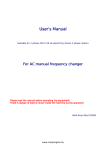
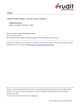
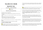
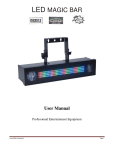
DV-5128 RGB IP 66
VERSION:V 1.0
This manual contains important operation information. Read and
understand all instructions prior to powering on unit the first time. Keep
this manual in a safe place for future reference.
WARNING
SAFETY INFORMATION (service personnel)
READ ALL CAUTIONS AND WARNINGS PRIOR TO OPERATE THIS EQUIPMENT
INSTRUCTION TO PREVENT INJURY OR DAMAGE DUE TO ELECTRIC SHOCK, FIRE, MECHANICAL
HAZARDS,
DANGEROUS
1 MATTERS.
USER MANUAL
This device has left our premises in absolutely perfect condition. In order to maintain this
condition and to ensure a safe operation, it is absolutely necessary for the user to follow
the safety instructions and warning notes written in this manual.
The manufacturer will not accept liability for any resulting damages caused by the
non-observance of this manual or any unauthorized modification to the device.
Please consider that damages caused by manual modifications to the device are not
subject to warranty.
Caution!
Indicates a skill or other useful information for special situations.
Important!
Indicates important information, to protect people from laser incident
or damage.
WARNING
Prevent damage or injury from incorrect operation.
Recycle
To protect the environment, recycle packing material wherever
possible.
•PROTECTION AGAINST DANGEROUS MATTERS
At the end of its working life, the product must not be disposed of as urban waste. It must
be taken to a special local authority differentiate waste collection centre or to a dealer
providing this service. The wrong disposal must be cause of environment and people
damages in the presence of possible dangerous matters. There are provided for sanctions
to a unauthorized disposal of these products.
•PROTECTION AGAINTS FIRE
1) Maintain minimum distance of 0.2 meter from walls or any other type flammable surfaces.
2) Maintain minimum distance of 0.2 meter to lighted objects .
3) Replace fuses (if present) only with the specified type and rating.
4) Do not install the spot close to heat sources. Do not lay the connection cable on the spot when it is
warm.
5) Fixture designed to be installed on normally flammable surfaces
•
•PROTECTION AGAINST ELECTRIC SHOCK
1) This equipment must be earthed.
1
USER MANUAL
2) Class I equipment. The power supply cord includes a protective earthing conductor as part of the
cord.
3) Disconnect power before servicing (service personnel).
•PROTECTION AGAINST MECHANICAL HAZARDS
1) Use secondary safety chain when fixing this equipment.
2) Equipment surface may reach temperature up to 60°C.
3) The protection screens and the lenses must be replaced with genuine parts only
if they are visibly damaged and their effectiveness has been
reduced, for example, by cracks or deep scratches.
Caution!
CONNECTION TO THE MAIN POWER
This equipment must be earthed.
Class I equipment. The power supply cord includes a protective earthing conductor as part of the cord.
IMPORTANT: to ensure the IP66 rate, in case of replacement of the conductor cable, refer to the
CONDUCTOR SIZE TABLE
•Make sure that the available voltage is not higher than stated on the rear panel of the fixture.
•Always disconnect the fixture from AC power before cleaning, removing or installing the fuses, or any
2
USER MANUAL
part.
•Do not overload wall outlets and extension cords as this can result in fire or electric shock.
•Make sure that the power/data cord is never crimped or damaged by sharp edges. Check the fixture
and the power/data cord from time to time.
•Do not install the unit near naked flames.
•Refer servicing to qualified service personnel.
DMX CONNECTION
DMX TERMINAL LINE
•The wrong connection of the terminal line or its non-connection are probably the most frequent
reasons for the defective functioning of the DMX line. The terminator is a terminal resistor fitted at the
end of the cable furthest from the transmitter.
•The terminal resistor should have the same value as the impedance of the connection cable.
•We suggest to use a terminal with a 100 ohm resistor.
•It is recommanded that all DMX 512 systems have the terminal resistor fitted in the DMX output of the
last fixture.
WARNING
LED light emission. Risk of eye injury
Do not look straight at the fixture′s LEDs during operation. The intense light beam may damage your eyes.
3
USER MANUAL
INSTALLATION
•When choosing the installation spot, please make sure that the fixture is not exposed to extreme heat
or dust.
•Avoid using the unit in locations subject to possible impacts.
•The fixture body never must be covered with cloth or other materials.
•Only operate the fixture after having checked that the housing is firmly closed and all screws are
tightly fastened.
•Make sure that the area below the installation place is blocked when rigging, derigging or servicing the
fixture.
•Do not block the front objective LEDs with any object when the fixture is under operation.
•The fixture becomes very hot during operation. Allow the fixture to cool approximately 40 minutes prior
tomanipulate with it.
•Operate the fixture only after having familiarized with its functions. Do not permit operation by persons
not qualified for operating the fixture. Most damages are the result of unprofessional operation!
•Do not attempt to dismantle or modify the unit.
•Please consider that unauthorized modifications on the fixture are forbidden due to safety reasons!
•Please use the original packaging if the fixture is to be transported.
•If this device will be operated in any way different to the one described in this manual, the product may
suffer damages and the guarantee becomes void. Furthermore, any other operation may lead to
dangers like shortcircuit, burns, electric shock etc.
FIXTURE EXTERIOR VIEW
•This device has left out premise in absolutely perfect condition. In order to maintain this condition and
to ensure safe operation, it is necessary for the user to follow the safety instructions and warning
notes written in this manual.
•The manufacturer will not accept liability for any resulting damages caused by the non-observance of
this manual or any unauthorized modification to the device.
4
USER MANUAL
1.
2.
3.
4.
5.
LED module
LED supply
Instal support
Power line and signal line for LED lamp
DMX in cable
6.
7.
8.
9.
DMX out cable
Power in cable
Power out cable
Control board
CONTROL & FUNCTION
•When fixture is powered on, LED monitor on rear panel shows the current
operating standalone mode or DMX address of DMX mode. With help of LED
control panel, it is very easy to set and change the operating mode of laser.
•After every resetting and saved, the new mode information will be shown on
LED monitor at next power on.
Mode Option, to choose the operating mode.
Confirmation, to confirm adjusted values and leaves menu(the parameter is flashing).
The UP/DOWN buttons allow to scroll forward/backward the menu list, sets values.
5
USER MANUAL
Master/slave connection
To build a master/slave-chain:
Connect the DMX output of the master fixture in the data chain with the DMX input of the first slave.
Always connect output with the input of the next slave until all slaves are connected.
Caution:
It is necessary to terminate the input of the master fixture and the output of the last slave with a
100 Ohm resistor in order to ensure the proper transmission on the data link.
Stand-alone operation
•The fixtures on a data link are not connected to the controller but can execute pre-set programs which
can be different for every fixture. To set the program to be played. "Stand-alone operation" can be
applied to the single fixture or to multiple fixtures operating synchronously. Synchronous operation of
multiple fixtures requires that they must be connected on a data link and one of them is set as a
master (master mode) and the rest as the slaves (slave mode).
•Only one fixture can be set as the master.
•The master fixture starts simultaneous program start in the other slave fixtures. All fixtures have a
definite, synchronized starting point when playing back their programs.
OPERATION
6
USER MANUAL
Fixture Menu
The control panel menu allows to set the fixture according to your needs, obtain information on its
operation, test its various parts and lastly program it, if it has to be used in a Stand-alone mode.
All InStand-alone model
LED Display function
DISPALY
MODE
FUNCTION
Manual
setting
R00-R99,G00-G99,B00-B99:(0-100% DIMMER,0 OFF,99 ON)
F00-F99:(Strobe Speed Adjusting,0 internal time,1 slowest,99
fastest)
D00-D99:(Gradual Change Control,0internal time,1slowest,99
fastest)
Note:Strobe and Gradual change cannot occur at the same time。
Color
hopping
FCH:Hopping time setting C00-C99(0internal time,1 slowest,99
fastest)
Color
Gradual
Change
FDH: dreamlike time control d00-d99(0 internal time,1 slowest,99
fastest)
Slave
function
As slave in master and slave model
DMX model
DMX address setting from 001-506 to 001-506
DMX Mode
Operating through a DMX controller give the user the freedom to create their own Programs tailored to
their own individual needs. This function also allows you to use your units as spot lights.
•This function will allow ypu to control each individual unit`s traits with a standard DMX 512 controller.
•The LED series uses 7DMX channels to operate. Please see “DMX Values and Functions” for the
DMX traits.
•To run your unit in DMX mode, plug in the unit via the XLR connections to any standard DMX
controller. Set your desired DMX address following the setup specifications that come with your DMX
controller.
7
USER MANUAL
CANNEL
FUNCTION
DESCRIPTION
CH 1
MODE
MAIN DIMMER
CH 2
selection
R DIMMER
CH 3
Strobe
G DIMMER
CH 4
B DIMMER
0-100% Blue
CH 5
Strobe time
control
Slow to fast
CH 6
Internal
program time
Slow to fast
0-100% DIMMER
0-100% Red
0-100% Green
000-057
Channels control CH1-CH4
058-107
Strobe speed control
108-123
CH 7
Function
selection
124-139
140-155
156-205
206-255
Brightness hanging from dark to bright,
gradual speed controlled by CH6
Brightness hanging from bright to dark,
gradual speed controlled by CH6
Brightness hanging, dark-bright-dark, gradual
speed controlled by CH6
7-color program automatically hopping, time
controlled by CH6
Romantic effect, time controlled by CH6
8
USER MANUAL
Technical Features
SOURCE:
ArkiShine 12TC-180 12*15W COB; RGB IP66. Total: 4150. 1180lm of R, 2400lm of G and 570lm of B
OPTIC:
ArkiShine 12TC-180 12*15W COB; RGB IP66.: 36°lenses
TILT: manual 180°
IP RATE: IP 66
CONTROL:
Standard interface: DMX512
Stand-alone operation
POWER SUPPLY:
Swithcing power supply(universal main voltage)
Rated voltage: 170-265V~; 50/60Hz
Rated voltage: 90-130V~; 50/60Hz
IP66, Self-Protection in Over-Load, Over-Voltage, Over-Heated
Rated power: 165W
DMX CHANNELS: 7channels
PHISICAL:
WxHxL: 200x250x600mm
Weight: 12.5kg
9