1
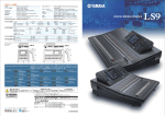
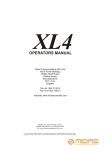
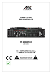
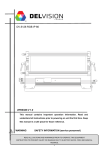
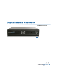
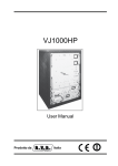
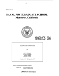
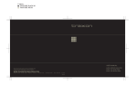
64PXL Board RGB
INSTALLATION GUIDE
V1.3
Cover:
64PXL Board RGB
8PXL Add-On Strip
16PXL Add-On Board
CONTENT
1. INTRODUCTION
3
2. installation
5
3. Safety And Operation
7
4. SYSTEM CONFIGURATION
8
5. Care and Maintenance
12
6. TECHNICAL SPECIFICATION
13
7. Troubleshooting
14
8. Warranty Statement
14
9. Add-On Fixtures
15
For your own safety and that of the product, please read this installation guide
carefully before beginning setup and installation.
www.traxontechnologies.com
©2015 traxon technologies - AN OSRAM Business. all rights reserved. traxon™, tx connect ® , are trademarks of traxon technologies. u.s. patents, e.u.
patents, japan patents, other patents pending. specifications are subject to change without notice.
Installation Guide
05/15 V1.3
2 of 18
1. INTRODUCTION
1.1 General
64PXL Board RGB features 64 ultra bright RGB SMD LEDs on a 8 x 8matrix with a
31.25mm/1.23” pitch. Although the LEDs provide ultra brightness, high resolution videos
and graphic replays can be created by combining multiple boards. The 64PXL Board is DMX
compatible which allows daisy chaining with the Traxon TX Connect™ system. On-board
SMART CHIP™ technology with the powerful feature of auto-addressing enables easy setup
and installation.
Features:
• 64 Ultra Bright RGB SMD LEDs
• TX Connect™ System
• DMX512 / e:pix / DVI capable
• Auto-Addressing
• SMART CHIP™ Technology
• Indoor Applications
www.traxontechnologies.com
©2015 traxon technologies - AN OSRAM Business. all rights reserved. traxon™, tx connect ® , are trademarks of traxon technologies. u.s. patents, e.u.
patents, japan patents, other patents pending. specifications are subject to change without notice.
Installation Guide
05/15 V1.3
3 of 18
DIMENSIONS
1.2 Dimensions
240mm/9.45”
16.00mm/0.63”
DIMENSIONS
222mm/8.74”
FIG.1: 64PXL Board RGB Dimensions
4.32mm/0.17”
222mm/8.74”
222mm/8.74”
222mm/8.74”
125mm/4.92” (2x)
31.25mm/1.23” (typ.)
240mm/9.45”
31.25mm/1.23” (typ.)
240mm/9.45”
16.00mm/0.63”
125mm/4.92” (2x)
240mm/9.45”
31.25mm/1.23” (typ.)
180mm/7.09” (2x)
4.32mm/0.17”
31.25mm/1.23” (typ.)
180mm/7.09” (2x)
1.3 PackingCONTENTS
Contents
2. PACKING
FIG.2: Packing Contents
2. PACKING CONTENTS
4 x Mounting Spacers
4 x Mounting Spacers
1 x 64PXL Board RGB
1 x 64PXL Board RGB
1 x TX Connect Smart Interconnection Cable (300mm/11.82”)
1 x TX Connect Smart Interconnection Cable (300mm/11.82”)
4 x Mounting Screws
4 x Mounting Screws
2
www.traxontechnologies.com
©2015 traxon technologies - AN OSRAM Business. all rights reserved. traxon™, tx connect ® , are trademarks of traxon technologies. u.s. patents, e.u.
patents, japan patents, other patents pending. specifications are subject to change without notice.
Installation Guide
05/15 V1.3
4 of 18
2. installation
2.1 Points To Consider
Plan your installation before mounting the String. The following should be considered for a
successful installation.
• Installation distances and appropriate cable lengths. Please consult your local Traxon™
office or authorized agent for necessary aid.
• The number of 64PXL Board RGBs and appropriate LED Engines.
• Any DMX512 controllers to be used with the products.
2.2 On-Site Installation
• ALWAYS keep the cables protected from sharp objects and ensure no
damage is generated on the cables.
• 4.Failure
to keep the product within the operating temperature range of 0°C
MOUNTING
to 50°C (+32°F to +122°F) and storage temperature range of −20°C to
+70°C (–4°F to +158°F) will void the product’s warranty.
4.1 BOARD
2.2.1 Mounting
To mount the Board, first fit the nylon spacers into the mounting holes from the rea
1. To mount thethe
board,
firstThen
fit theuse
nylon
the mounting
from
of
board.
thespacers
screws into
to firmly
fasten theholes
board
to athe
flatrear
surface.
Careful
the board. Then
use the screws
to firmly(see
fasten
to over-tighten
the screws
FIGthe
1). board to a flat surface. Careful not to
over-tighten the screws, see below diagram.
FIG 1: Board
Mounting
FIG.3: Board
Mounting
125mm/4.92”
MOUNTING SPACER (4x)
SCREW (4x)
www.traxontechnologies.com
To keep a consistent LED pitch when mounting mulltiple boards, use the dimens
shown in FIG 2.
©2015 traxon technologies - AN OSRAM Business. all rights reserved. traxon™, tx connect ® , are trademarks of traxon technologies. u.s. patents, e.u.
patents, japan patents, other patents pending. specifications are subject to change without notice.
Installation Guide
05/15 V1.3
5 of 18
2. To keep a consistent LED pitch when mounting multiple boards, use the dimensions
shown in below diagram.
FIG 2: Mounting Multiple Boards
FIG.4: Mounting Multiple Boards
30mm/1.81”
180mm/7.09”
70mm/2.76”
180mm/7.09”
31.25mm/1.23”
31.25mm/1.23”
31.25mm/1.23”
10mm/0.39”
125mm/4.92”
125mm/4.92”
125mm/4.92”
57.5mm/2.26”
10mm/0.39”
31.25mm/1.23”
31.25mm/1.23”
31.25mm/1.23”
5
www.traxontechnologies.com
©2015 traxon technologies - AN OSRAM Business. all rights reserved. traxon™, tx connect ® , are trademarks of traxon technologies. u.s. patents, e.u.
patents, japan patents, other patents pending. specifications are subject to change without notice.
Installation Guide
05/15 V1.3
6 of 18
3. Safety And Operation
• CAUTION - Unplug the power supply from the mains power before connecting any cables
as this can damage the products.
• CAUTION - Avoid looking directly into the LED light source at close range for your own
safety.
• Persons installing this products should make sure:
1. The installation complies with all applicable codes, state and local laws,
ordinances, standards and safety regulations.
2. The installation environment is carefully studied and suitable surge protection
measure(s) is taken.
3. He or she is qualified for the handling of electrical equipment.
• Do not attempt to install or use the product until installation instructions and safety labels
are fully understood. This product is designed for indoor use only.
• Ensure product operates within the specified temperature range. (Refer to 6. TECHNICAL
SPECIFICATION for more details.)
• Do not attempt to open the product. Not user serviceable.
• Do not use the product if any part of it, or the power cables are damaged.
• Only use product for specified voltage, do not exceed. (Refer to 6. TECHNICAL
SPECIFICATION for more details.)
• If the product has been subjected to drastic temperature variances, for example, following
transportation, do not connect the fixture until it has reached room temperature, as
moisture condensation may cause electric shock and product damages.
• When installing the products and system power supplies, please ensure they will not be
exposed to moisture and extreme heat. Besides, keep a clean operating environment for
the fixtures and system power supplies.
• Please study this Installation Guide thoroughly and check the latest Technical Specification
Sheets available from the Traxon website www.traxontechnologies.com before setup.
• Any non-compliance of the Installation Guide will void the Traxon warranty.
www.traxontechnologies.com
©2015 traxon technologies - AN OSRAM Business. all rights reserved. traxon™, tx connect ® , are trademarks of traxon technologies. u.s. patents, e.u.
patents, japan patents, other patents pending. specifications are subject to change without notice.
Installation Guide
05/15 V1.3
7 of 18
4. SYSTEM CONFIGURATION
4.1 TYPICAL CONNECTION COMPONENTS
TX Connect System is a interconnection system that combines power and DMX data on
a single connector cables so that only one connection is required between light fixutres.
The Board uses TX Connect System for all interconnections. Below diagram shows some
components for the TX Connect System
FIG.5: TX Connect System Components
TX Connect Data Cable
Part No.:
DI.IC.0020000
DI.IC.0300000
DI.IC.1000000
Butler S2
DMX/RDM Output Engine
EN.BU.0000001
Video Micro Converter
Part No.: 160185
0.2m
3m
10m
DI.IC.0100000
DI.IC.0500000
DI.IC.2000000
1m
5m
20m
Butler S2
Part No.: EN.BU.0000001
TX Connect Smart Power Injector Cable
Part No.: TI.PI.0000100
TX Connect Smart Interconnection Cable
LED Engine Smart 100W Indoor
Part No.: PS.IA.0010000
Part No.:
TI.IC.0008000
0.08m
TI.IC.0030000
0.3m
TI.IC.0060000
0.6m
TX Connect Smart Extension Cable
Part No.:
TX Connect Smart
Power/Data Injector Box
Part No.: TI.ZI.0000100
TX Connect Smart
Data Extractor Box
Part No.: TI.DO.0000100
TI.EC.0050000
0.5m
TI.EC.0100000
1m
TI.EC.0300000
3m
TI.EC.0500000
5m
TI.EC.1000000
10m
www.traxontechnologies.com
©2015 traxon technologies - AN OSRAM Business. all rights reserved. traxon™, tx connect ® , are trademarks of traxon technologies. u.s. patents, e.u.
patents, japan patents, other patents pending. specifications are subject to change without notice.
Installation Guide
05/15 V1.3
8 of 18
Installation Guide
AC Power Cord
05/15 V1.3
CONTROLLER
Butler S2
Butler S2
POWER SUPPLY
100W Indoor
LED Engine Smart
C
A
TX Connect Data Cable
512 DMX Channels per output
Interconnection Cable
TX Connect Smart
TX Connect Smart
Power/Data Injector Box
Back
Back
TX Connect Smart
Power Injector Cable
TX Connect Smart Extension Cable
TX Connect Smart Interconnection Cable
D
64PXL Board RGB
POWER SUPPLY to last FIXTURE in chain.
C to D: 30 meters
CONTROLLER to first FIXTURE.
A to B: 100 meters
CABLING LENGTHS
PER CONTROLLER OUTPUT (512 DMX CHANNELS).
2x 64PXL BOARD RGB CAN BE DAISY CHAINED
ONE LED ENGINE SMART 100W INDOOR.
4x 64PXL BOARD RGB CAN BE POWERED BY
B
FIG.6: System Diagram - Butler S2
www.traxontechnologies.com
©2015 traxon technologies - AN OSRAM Business. all rights reserved. traxon™, tx connect ® , are trademarks of traxon technologies. u.s. patents, e.u.
patents, japan patents, other patents pending. specifications are subject to change without notice.
9 of 18
Installation Guide
05/15 V1.3
A
LCE2 fx
DVI
Source
PSU6
PSU5
PSU4
PSU3
PSU2
PSU6 O/P1
PSU5 O/P3
PSU5 O/P2
PSU5 O/P1
PSU4 O/P3
PSU4 O/P2
PSU4 O/P1
PSU3 O/P3
PSU3 O/P2
PSU3 O/P1
PSU2 O/P3
PSU2 O/P2
PSU2 O/P1
PSU1 O/P3
PSU1 O/P2
PSU1 O/P1
CHAINED PER VMC OUTPUT.
UP TO EIGHT 64PXL BOARD RGBs CAN BE DAISY
Configured to grab 4096 pixels
from DVI input.
Video Micro Converter (VMC)
PSU5 DMX IN 3
PSU5 DMX IN 1
PSU4 DMX IN 2
PSU3 DMX IN 3
PSU3 DMX IN 1
PSU2 DMX IN 2
PSU1 DMX IN 3
PSU1
LED Engine Smart 300W Indoor
PSU1 DMX IN 1
TX Connect Data Cable
Configuration
via Ethernet
C
B
TX Connect Smart Interconnection Cable
(300mm length included with each board)
D
BY ONE O/P OF LED ENGINE SMART 300W INDOOR.
UP TO FOUR 64PXL BOARD RGBs CAN BE POWERED
Back View
Back View
Back View
64PXL Board RGB
POWER SUPPLY to last FIXTURE in chain.
C to D: 30 meters
CONTROLLER to first FIXTURE.
A to B: 100 meters
CABLING LENGTHS
TX Connect Smart Power Injector Cable
FIG.7: System Diagram - VMC
www.traxontechnologies.com
©2015 traxon technologies - AN OSRAM Business. all rights reserved. traxon™, tx connect ® , are trademarks of traxon technologies. u.s. patents, e.u.
patents, japan patents, other patents pending. specifications are subject to change without notice.
10 of 18
CONNECTING BETWEEN
FIXTURES
4.2 5.3Connection
between
Fixtures
5.3 CONNECTING BETWEEN FIXTURES
Use the TX BETWEEN
Connect Smart
Interconnection Cable to connect between boards (FIG 6).
5.3 CONNECTING
Use
the TX Connect
Smart FIXTURES
Interconnection Cable to connect between boards. Use the
Use
Connect Smart
Cable to
connectFor
between
(FIGuse
6).
Use the
the TX
pre-installed
cablesInterconnection
to connect between
Modules.
longer boards
distances,
pre-installed
cables
to connect
between
modules.
ForModules.
longer distances,
existing
cable
the
pre-installed
cables
between
For boards
longer use
distances,
use
Use theUse
TX Connect
Smart
Interconnection
Cable
to connect
between
(FIG 6).
existing
cable
together
with a to
TXconnect
Connect
Smart
Extension
Cable.
together
with acable
TX Connect
Smart
Extension
Cable.
together
with
a TX
Connect
Extension
Cable.distances, use
Use theexisting
pre-installed
cables to
connect
betweenSmart
Modules.
For longer
FIG 6: Connecting Fixtures
FIG 7: LED Positions on the Board
FIG.8: FIG
Connecting
Fixtures
FIG.9: LED Positions
existing
cable
together
with
a TX Connect Smart Extension
6:
Connecting
Fixtures
FIG 7: LEDCable.
Positions
on the Board on Board
FIG 6: Connecting Fixtures
FIG 7: LED Positions
the Board
(1,1) on
(2,1)
(3,1) (4,1)
BOARD CONNECTION
BOARD CONNECTION
(1,1)
(1,2)
BOARD CONNECTION
(1,3)
(1,4)
(1,5)
(1,6)
(1,7)
5.4 LED CONTROL
4.3 5.4
LED
Control
LED CONTROL
(1,8)
(5,1)
(6,1)
(7,1)
(8,1)
(1,1) (2,1) (3,1) (4,1) (5,1) (6,1) (7,1)
(1,2) (2,2) (3,2) (4,2) (5,2) (6,2) (7,2)
(2,1) (3,1) (4,1) (5,1) (6,1) (7,1) (8,1)
(1,2) (2,2) (3,2) (4,2) (5,2) (6,2) (7,2)
(1,3) (2,3) (3,3) (4,3) (5,3) (6,3) (7,3)
(2,2) (3,2) (4,2) (5,2) (6,2) (7,2) (8,2)
(1,3) (2,3) (3,3) (4,3) (5,3) (6,3) (7,3)
(1,4) (2,4) (3,4) (4,4) (5,4) (6,4) (7,4)
(2,3) (3,3) (4,3) (5,3) (6,3) (7,3) (8,3)
(1,4) (2,4) (3,4) (4,4) (5,4) (6,4) (7,4)
(1,5) (2,5) (3,5) (4,5) (5,5) (6,5) (7,5)
(2,4) (3,4) (4,4) (5,4) (6,4) (7,4) (8,4)
(1,5) (2,5) (3,5) (4,5) (5,5) (6,5) (7,5)
(1,6) (2,6) (3,6) (4,6) (5,6) (6,6) (7,6)
(2,5) (3,5) (4,5) (5,5) (6,5) (7,5) (8,5)
(1,6) (2,6) (3,6) (4,6) (5,6) (6,6) (7,6)
(1,7) (2,7) (3,7) (4,7) (5,7) (6,7) (7,7)
(2,6) (3,6) (4,6) (5,6) (6,6) (7,6) (8,6)
(1,7) (2,7) (3,7) (4,7) (5,7) (6,7) (7,7)
(1,8) (2,8) (3,8) (4,8) (5,8) (6,8) (7,8)
(2,7) (3,7) (4,7) (5,7) (6,7) (7,7) (8,7)
(1,8) (2,8) (3,8) (4,8) (5,8) (6,8) (7,8)
(8,1)
(8,2)
(2,8)
(3,8)
(4,8)
(5,8)
(6,8)
(7,8)
(8,2)
(8,3)
(8,3)
(8,4)
(8,4)
(8,5)
(8,5)
(8,6)
(8,6)
(8,7)
(8,7)
(8,8)
(8,8)
(8,8)
LEDs on the 64PXL Board RGB are controlled by DMX. The LED location and on
5.4 LEDThe
CONTROL
The
LEDs
on
the
Board
are incontrolled
by
LED
location
The LEDs
the and
64PXL
board
RGBisRGB
are
controlled
DMX.
TheThe
LED
location
onand
theonBoard
theon
Board
its 64PXL
DMX
channel
shown
FIG 7by
and
theDMX.
following
table.
the on
Board
its
DMX
channel
is shown
in FIG
7DMX.
and
following
table.
and
DMX
channel
is shown
in above
diagram
and
in the
following
table.and on
Theits
LEDs
the and
64PXL
Board
RGB
are
controlled
by
The
LED location
LED Dice
LED Dice
R
LED Dice R
G
DMX Channel Number
DMX Channel Number
192(n-1) + 24(x-1) + 3(y-1) + 1
DMX192(n-1)
Channel Number
192(n-1) +
+ 24(x-1)
24(x-1) +
+ 3(y-1)
3(y-1) +
+ 12
the Board and its DMX channel is shown in FIG 7 and the following table.
R
192(n-1)192(n-1)
+ 24(x-1)+
3(y-1) +
13(y-1) +
G
192(n-1)
++24(x-1)
24(x-1)
+ 3(y-1)
+ 23
B
192(n-1)
++24(x-1)
+ 3(y-1)
+3
B
192(n-1)
+
24(x-1)
3(y-1)
2
Where: n is the Board position in the chain.
192(n-1)
+ 24(x-1)in
+the
3(y-1)
+ 3the Board.
B Where: nx is
Board
position
chain.
is the
the
LED horizontal
position
on
xy is
LED
position
Board.
Where: n is the Board
in theposition
chain.
is the
theposition
LED horizontal
vertical
onon
thethe
Board.
y is the
LED vertical
position
the Board.
x is the LED
horizontal
position
on theon
Board.
G
9
9
y is theON:
LEDThe
vertical
position
on the
Board.
POWER
64PXL
Board
RGB
has an approximately one second initialization
POWER
ON:power-on.
The 64PXL
Board
hasthe
anLEDs
approximately
onemay
second
initialization
period after
During
thisRGB
period,
on the board
light up
randomly.
period
after
power-on.
During
this
period,
the LEDs on the
mayinitialization
light up randomly.
POWER
ON:
64PXL
Board
RGB
has
an approximately
oneboard
second
This
is The
normal
behavior
of the
Board.
Power
Board
RGB
an approximately
second
initialization
period after
This 64PXL
is
normal
behavior
of has
the
Board.
period On:
after
power-on.
During
this
period,
the LEDs on theone
board
may light
up randomly.
power-on.
During
this of
period,
the LEDs on the board may light up randomly. This is normal
This is normal
behavior
the Board.
behavior of the board.
www.traxontechnologies.com
©2015 traxon technologies - AN OSRAM Business. all rights reserved. traxon™, tx connect ® , are trademarks of traxon technologies. u.s. patents, e.u.
patents, japan patents, other patents pending. specifications are subject to change without notice.
Installation Guide
05/15 V1.3
11 of 18
5. Care and Maintenance
Traxon™ products are of superior design and quality and should be treated with care. The
recommendations below will help fulfill any warranty obligations and gain good use and
longevity from the products.
• Do not attempt or use the product(s) until you read and understand the installation
instructions. Failure to adhere to these instructions could result in serious injury or property
damage.
• Do not use product(s) if cables are damaged.
• Do not connect cables and connectors when wet or in wet area. Moisture on bare
connectors can cause electric shock and damage to product(s).
• Do not use product(s) in extreme heat environment. Ensure there is sufficient airflow and
use cool air circulation if required.
• Do not drop, knock, or shake product(s). Rough handling can damage the electronics and
void the warranty.
• Do not use harsh chemicals, cleaning solvents, or strong detergents to clean products.
Wipe with a damp cloth on housings and a dry cloth on electronics to remove dirt or dust.
• Do not use product(s) outdoors.
• Do not attempt to service or repair the product(s) unless done by an authorized service
personnel. Contact your local Traxon office or distributor for details.
• If the product is not working as specified, please contact your nearest authorized service
center or Traxon Technologies office for assistance.
www.traxontechnologies.com
©2015 traxon technologies - AN OSRAM Business. all rights reserved. traxon™, tx connect ® , are trademarks of traxon technologies. u.s. patents, e.u.
patents, japan patents, other patents pending. specifications are subject to change without notice.
Installation Guide
05/15 V1.3
12 of 18
6. TECHNICAL SPECIFICATION
64PXL Board RGB
Color Range
16.7 Million additive RGB colors with variable intensity
Light Source
64 Ultra Bright SMD LED
Beam Angle
120°
Power Input*
24V DC
Power Consumption
24W max.
Operating Temperature
0°C to +50°C / +32°F to +122°F
Storage Temperature
–20°C to 70°C / –4°F to +158°F
*For use with TRAXON LED Engine Smart 100W Indoor (PS.IA.0010000) power unit.
This device complies with Part 15 of the FCC Rules. Operation is subject to the following two
conditions: (1) this device may not cause harmful interference, and (2) this device must accept
any interference received, including interference that may cause undesired operation.
As with all electronic devices, LED output degrades over time - a term called lumen
depreciation. This also explains why it is nearly impossible to expect photometric
performances of two LED products with different service life spans to be the same. The
rate of LED degradation is a complex function of many factors such as operating efficiency,
duration of continuous operation, and operating conditions (e.g. ambient temperature).
Because LEDs are semiconductor devices, their performances are subject to inherent
variability commonly found in semiconductor industry. To improve consistency in performance
across the same product, LED manufacturers “sort” LEDs into bins according to different
preset parameters, such as forward driving voltage, illumination, etc. Whereas binning is a
sorting function, it is not a correction process. Inherent variability in the manufacturing process
always results in different binning distributions according to different production lots. Traxon
uses automatically binned LEDs on its products, thereby minimizing output variations within
the model range.
www.traxontechnologies.com
©2015 traxon technologies - AN OSRAM Business. all rights reserved. traxon™, tx connect ® , are trademarks of traxon technologies. u.s. patents, e.u.
patents, japan patents, other patents pending. specifications are subject to change without notice.
Installation Guide
05/15 V1.3
13 of 18
7. Troubleshooting
CAUTION: Ensure power supply is OFF when disconnecting / connecting
cables.
Problem
Cause
Possible Solutions
Product does
NOT light up
after installation
Incorrect power
connection
• Check Mains Power
• Check power supply leads and wire
connections
• Ensure output wires are connected
with proper polarity
Shadowing
Light source covered
• Check for cables, wires or unwanted
debris covering LED light source
Modules are
dim
Excess products
connected
• Ensure the power supplies are not
overloaded due to an excess of
products connected
Flickering
Incorrect power input/
Excess products
connected
• Ensure the input voltage is correct
• Ensure the power supplies are not
overloaded due to an excess of
products connected
If problems persist or the product is not working as specified, please contact your nearest
authorized service center or Traxon Technologies office for assistance.
8. Warranty Statement
Traxon Technologies warrants its Products against material or workmanship defects for a
period of five (5) years from date of purchase, provided that the purchased items are used
under the conditions stated in this user manual.
Please refer www.traxontechnologies.com for all warranty terms and conditions.
www.traxontechnologies.com
©2015 traxon technologies - AN OSRAM Business. all rights reserved. traxon™, tx connect ® , are trademarks of traxon technologies. u.s. patents, e.u.
patents, japan patents, other patents pending. specifications are subject to change without notice.
Installation Guide
05/15 V1.3
14 of 18
9. Add-On Fixtures
8PXL 9.
Add-On
Strip FIXTURES
RGB 31.25 (MB.ST.7213000)
ADD-ON
16PXL8PXL
Add-On
Board
31.25
(MB.BO.7110100)
ADD-ON
STRIPRGB
RGB 31.25
(MB.ST.7213000)
16PXL ADD-ON BOARD RGB 31.25 (MB.BO.7110100)
8PXL Add-On Strip and 16PXL Add-On Board are Add-On extensions for the 64PXL Board
Add-on
16PXL
Board for
are all
add-on
extensions for the 64PXL
RGB. The
The8PXL
Add-On
StripStrip
andand
Board
useAdd-on
TX Connect
interconnections.
Board RGB. The Add-on Strip and Board use TX Connect for all interconnections.
9.1 Dimensions
9.1 DIMENSIONS
FIG.10: Add-On Strip (31.25) / Add-On Board (31.25)
ADD-ON STRIP (31.25)
ADD-ON BOARD (31.25)
9mm/0.35”
Ø5.85mm/0.23” (2x)
115mm/4.53”
115mm/4.53”
31.25mm/1.23” typ. pitch
57.50mm/2.26”
31.25mm/1.23” typ. pitch
240mm/9.45”
Ø5.85mm/0.23” (2x)
31.25mm/1.23” typ. pitch
10.6mm/0.42”
57.5mm/2.26” 125mm/4.92”
21.20mm/0.83”
8mm/0.31”
55mm/2.17” 30mm/1.18”
1 x TX Connect Smart Interconnection Cable (300mm/11.81”)
1 x TX Connect Smart Interconnection Cable (300mm/11.81”)
1 x TX Connect Smart Interconnection Cable (40mm/1.57”)
1 x TX Connect Smart Interconnection Cable (80mm/3.15”)
2 x Mounting Spacers
2 x Mounting Spacers
2 x Mounting Screws
2 x Mounting Screws
9.2 TECHNICAL SPECIFICATION
9.2 Technical Specifications
Color Range:
16.7 million additive RGB colors with variable intensity
Light
Source:
8 / Board
16 Ultra(31.25)
Bright SMD LED
Add-On Strip (31.25) / Add-On
Beam Angle:
120°
Color Range
16.7 Million additive RGB colors with variable intensity
Power Input:
24V DC
LightPower
Source
85W
/ 16
Ultra
Bright SMD LED
Consumption:
max.
(MB.ST.7213000),
10W max. (MB.BO.7110100)
Operating
0°C to 50°C (32°F to 122°F)
Beam
Angle Temperature: 120°
Power Input*
24V DC
Power Consumption
5W max. (MB.ST.7213000), 10W max. (MB.BO.7110100)
Operating Temperature
0°C to +50°C / +32°F to +122°F
12
www.traxontechnologies.com
©2015 traxon technologies - AN OSRAM Business. all rights reserved. traxon™, tx connect ® , are trademarks of traxon technologies. u.s. patents, e.u.
patents, japan patents, other patents pending. specifications are subject to change without notice.
Installation Guide
05/15 V1.3
15 of 18
FIG.11: Mounting 64PXL Board RGB with Add-On Strips and Add-On Boards
FIG 8: Mounting 64PXL Board RGB with Add-on Strips and Add-on Boards
31.25 [1.23]
10.6 [0.42]
KEEP LED PITCH (31.25mm)
CONSISTENT WHEN MOUNTING.
10 [0.39]
Dimensions in mm [inch]
55 [2.17]
55 [2.17]
125 [4.92]
10 [0.39]
125 [4.92]
125 [4.92]
70 [2.76]
10 [0.39]
10 [0.39]
(1)
(2)
64PXL Board RGB
30 [1.18]
(3)
10 [0.39]
180 [7.09]
50.6 [1.99]
50.6 [1.99]
DMX CHANNEL ALLOCATION
LED Dice
DMX Channel Number
RED
GREEN
Start Address + 3L - 3
BLUE
Start Address + 3L - 1
Start Address + 3L - 2
Where: L is the LED position on the board.
LED POSITIONS
ON THE ADD-ON
STRIP AND BOARD.
(4)
(5)
(1)
(5)
(9)
(13)
(6)
(2)
(6)
(10)
(14)
(7)
(3)
(7)
(11)
(15)
(8)
(4)
(8)
(12)
(16)
www.traxontechnologies.com
©2015 traxon technologies - AN OSRAM Business. all rights reserved. traxon™, tx connect ® , are trademarks of traxon technologies. u.s. patents, e.u.
patents, japan patents, other patents pending. specifications are subject to change without notice.
Installation Guide
05/15 V1.3
16 of 18
Installation Guide
0
16PXL Add-on Board (31.25)
AC Power Cord
(PS.AC.xxxxxxx)
5
8PXL Add-on Strip (31.25)
consume the power equivalent to
ONE 64PXL Board RGB.
2
0
1
3
2
1
The following Add-on Strip/Board combinations
05/15 V1.3
CONTROLLER
Butler S2
Butler S2
POWER SUPPLY
LED Engine Smart
100W Indoor
(PS.IA.0010000)
C
A
(MB.BO.7110100)
16PXL Add-on Board (31.25)
D
8PXL Add-on Strip (31.25)
(MB.ST.7213000)
Back
64PXL Board RGB
POWER SUPPLY to last FIXTURE in chain.
C to D: 30 meters
CONTROLLER to first FIXTURE.
A to B: 100 meters
CABLING LENGTHS
PER CONTROLLER OUTPUT (512 DMX CHANNELS).
2x 64PXL BOARD RGB CAN BE DAISY CHAINED
ONE LED ENGINE SMART 100W INDOOR.
4x 64PXL BOARD RGB CAN BE POWERED BY
TX Connect Smart
Power Injector Cable
(TI.PI.0000100)
B
Back
CAUTION: PLEASE ENSURE THAT THE POWER IS SWITCHED OFF WHEN THE
DATA CABLES ARE BEING CONNECTED. FAILURE TO DO SO WILL RESULT IN
DAMAGE TO THE PRODUCTS AND VOID THE PRODUCT WARRANTY.
TX Connect Data Cable
(DI.IC.xxxxxxx)
512 DMX Channels per output
TX Connect Smart
Interconnection Cable
(TI.IC.xxxxxxx)
(TI.ZI.0000100)
TX Connect Smart
Power/Data Injector Box
TX Connect Smart Extension Cable (TI.EC.xxxxxxx)
TX Connect Smart Interconnection Cable (TI.IC.xxxxxxx)
FIG.12: 64PXL Board RGB with Add-On Strip and Add-On Board Connection
Example
FIG 9: 64PXL Board RGB with Add-on Strip and Add-on Board Connection Example
www.traxontechnologies.com
©2015 traxon technologies - AN OSRAM Business. all rights reserved. traxon™, tx connect ® , are trademarks of traxon technologies. u.s. patents, e.u.
patents, japan patents, other patents pending. specifications are subject to change without notice.
17 of 18
Please check for the latest updates and changes on the Traxon website.
© 2015 TRAXON TECHNOLOGIES ALL RIGHT RESERVED. Information is subject to change without prior notice.
www.traxontechnologies.com