1
1336 PLUS II
Adjustable
Frequency AC Drive
AQF05 - AQF75
BRF05 - BRF200
CWF10, CWF20 - CWF200
Troubleshooting Guide
Important User Information
Solid state equipment has operational characteristics differing from those of
electromechanical equipment. “Safety Guidelines for the Application,
Installation and Maintenance of Solid State Controls” (Publication SGI-1.1
available from your local Allen-Bradley Sales Office or online at http://
www.ab.com/manuals/gi) describes some important differences between
solid state equipment and hard-wired electromechanical devices. Because of
this difference, and also because of the wide variety of uses for solid state
equipment, all persons responsible for applying this equipment must satisfy
themselves that each intended application of this equipment is acceptable.
In no event will the Allen-Bradley Company be responsible or liable for
indirect or consequential damages resulting from the use or application of
this equipment.
The examples and diagrams in this manual are included solely for
illustrative purposes. Because of the many variables and requirements
associated with any particular installation, the Allen-Bradley Company
cannot assume responsibility or liability for actual use based on the
examples and diagrams.
No patent liability is assumed by Allen-Bradley Company with respect to
use of information, circuits, equipment, or software described in this
manual.
Reproduction of the contents of this manual, in whole or in part, without
written permission of the Allen-Bradley Company is prohibited.
Throughout this manual we use notes to make you aware of safety
considerations.
!
ATTENTION: Identifies information about practices or
circumstances that can lead to personal injury or death, property
damage, or economic loss.
Attentions help you:
• identify a hazard
• avoid the hazard
• recognize the consequences
Important: Identifies information that is especially important for successful
application and understanding of the product.
Shock Hazard labels may be located on or inside the drive to
alert people that dangerous voltage may be present.
SCANport is a trademark of Rockwell Automation.
PLC is a registered trademark of Rockwell Automation.
COLOR-KEYED is a registered trademark of Thomas & Betts Corporation.
IBM is a registered trademark of International Business Machines Corporation.
Windows 95 is a registered trademark of Microsoft Corporation.
Chapter
1
Introduction
Manual Objectives
This document is intended as a supplementary addition to the 1336 PLUS
6.1 Troubleshooting Guide. This supplement covers the additional
information you will need to help troubleshoot or repair an Allen-Bradley
Bulletin 1336 PLUS II Adjustable Frequency AC Drive with A1 - A4
Frames.
Who Should Use This
Manual
This manual is intended for qualified service personnel responsible for
troubleshooting and repairing the 1336 PLUS II Adjustable Frequency AC
Drive. You should:
• Read this entire manual before performing maintenance or repairs to
drives.
• Have previous experience with, and basic understanding of, electrical
terminology, procedures, required troubleshooting equipment, equipment
protection procedures and methods, and safety precautions.
!
ATTENTION: Some printed circuit boards and drive
components may contain hazardous voltage levels. Remove and
lock out power before you disconnect or reconnect wires, and
before you remove or replace fuses and circuit boards. Verify bus
voltage by measuring the voltage between +DC and -DC on
Terminal Block TB1. Do not attempt to service the drive until the
bus voltage has discharged to zero volts.
ATTENTION: Potentially fatal voltages may result from
improper useage of oscilliscope and other test equipment. The
oscilliscope chassis may be at a potentially fatal voltage if not
properly grounded. If an oscilliscope is used to measure high
voltage waveforms, use only a dual channel oscilliscope in the
differential mode with X 100 probes. It is recommended that the
oscilliscope be used in the A minus B Quasi-differential mode with
the oscilloscope chassis correctly grounded to an earth ground.
ATTENTION: Only personnel familiar with the 1336 PLUS II
AC Drive and associated machinery should plan or implement the
installation, start-up and subsequent maintenance of the system.
Failure to comply may result in personal injury and/or equipment
damage.
1-2
Introduction
Electrostatic Discharge
!
ATTENTION: This assembly contains parts and
sub-assemblies that are sensitive to electrostatic discharge. Static
control precautions are required when servicing this assembly.
Component damage may result if you ignore electrostatic
discharge control procedures. If you are not familiar with static
control procedures, reference Allen-Bradley Publication
8000-4.5.2, Guarding Against Electrostatic Damage, or any other
applicable ESD protection handbook.
Electrostatic discharge generated by static electricity can damage the
complimentary metallic oxide semiconductor devices on various drive
boards. It is recommended that you perform these procedures to guard
against this type of damage when circuit boards are removed or installed:
• Wear a wrist-type grounding strap that is grounded to the drive chassis.
• Attach the wrist strap before removing the new circuit board from the
conductive packet.
• Remove boards from the drive and immediately insert them into their
conductive packets.
1336 PLUS II Product
Identification
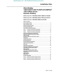
Drive Nameplate Location - The drive nameplate is located on the
the Main Control Board Mounting Plate on B thru G frame drives and on
the chassis of A frame drives. The drive nameplate contains the drive’s
catalog number and other important drive information. Reference the
catalog number when ordering replacement parts.
Figure 1.1
Drive Nameplate Location
1 Refer
to page 1-1 for frame reference classifications.
Frames1 A1, A2, A3, A4
Nameplate Located on
Bottom Portion of
Chassis Behind Cover
1336 PLUS - 6.16 - September, 2001
Introduction
1-3
Software Compatibility
Three-Phase Drive Rating 1
200-240V
0.37-0.75 kW
0.5-1 HP
1.2-1.5 kW
1.5-2 HP
2.2-3.7 kW
3-5 HP
5.5 kW
7.5 HP
380-480V
0.37-1.2 kW
0.5-1.5 HP
1.5-2.2 kW
2-3 HP
3.7 kW
5 HP
5.5-15 kW
7.5-20 HP
500-600V
–
Compatible with
Version . . .
1.0 & Up
Frame
Reference
A1
–
1.0 & Up
A2
–
1.0 & Up
A3
0.75-15 kW
1-20 HP
1.0 & Up
A4
1 kW and HP are constant torque.
Drive and Option
Identification
The following is an explanation of the catalog numbering system for the
PLUS II Adjustable Frequency AC Drives and options. The catalog number
is coded to identify the drive power rating and can be found on the drive
shipping carton and nameplate.
1336 PLUS-6.16 - September, 2001
1-4
Introduction
1336 PLUS II Drive Catalog Numbers
1336F – BR
F30
First Position
Second Position
Third Position
Fourth Position
Fifth Position
Sixth Position
Bulletin Number
Voltage
Nominal HP Rating
Enclosure Type
Language Group ➀
Options
Code Type
Code Language
AA
IP 20 (NEMA 1)
AE
IP 20 (NEMA 1)/EMC
AF
IP 65 (NEMA 4) ➂
AJ
IP 54 (NEMA 12) ➂
AN
IP 00 (Open)
EN
FR
DE
IT
ES
JP
Letter
Voltages
AQ
200-240V AC or
310V DC
BR
380-480VAC or
513-620V DC
CW
500-600V AC or
775V DC
A
200-240V AC
B
380-480V AC
BP/BPR ➃380-480V AC
(F Frame)
BX
Special Rating
C
500-600V AC
CP/CPR ➃500-600V AC
(F Frame)
Q
310V DC
R
513-620V DC
RX
Special Rating
W
775V DC
– EN
– AA
Refer to table below for
ratings and possible
voltage combinations.
Code
– MODS
English
French
German
Italian
Spanish
Japanese
Description
Human Interface Module, Snap-In, IP20 (NEMA Type 1)
HASB Snap-In Cradle/Blank Plate
HASP Programmer Only
HCSP Programmer Only & Upload/Download Capability
HAS1 Programmer/Controller w/Analog Pot
HCS1 Programmer/Controller w/Analog Pot & Upload/Download Capability
HAS2 Programmer/Controller w/Digital Pot
HCS2 Programmer/Controller w/Digital Pot & Upload/Download Capability
Human Interface Module, IP65/54 (NEMA Type 4/12)
HJP
Programmer Only
HJ2
Programmer/Controller w/Digital Pot
Voltage and Nominal HP Rating Combinations
Communication Options –- B Frame & Up (Adapter 6)
GM1
Single Point Remote I/O B Frame
BP/
CP/
Code Rating
AQ BR CW A B BPR BX C CPR Q R RX W
GM2
RS-232/422/485, DF1 & DH485 B Frame
● ●
F05
0.37 (0.5)
GM5
DeviceNet™
● ●
F07
0.56 (0.75)
GM6
Enhanced DeviceNet™
● ● ●
F10
0.75 (1)
Communication Options –- All Frames (Adapter 1)
● ●
F15
1.2 (1.5)
GMS1 GM1 with Snap-In Cradle
● ● ●
F20
1.5 (2)
GMS2 GM2 with Snap-In Cradle
● ● ●
F30
2.2 (3)
GMS5 GM5 with Snap-In Cradle
● ● ●
F50
3.7 (5)
GMS6 GM6 with Snap-In Cradle
● ● ●
F75
5.5 (7.5)
Control Interface Options
● ●
F100 7.5 (10)
● ●
F150 11 (15)
L4
TTL Contact
● ●
F200 15 (20)
L4E
TTL Contact & Encoder Feedback
●
●
007
5.5 (7.5)
L7E
TTL Contact & Encoder Fdbck. for use with Encoder Loss Detection
●
●
010
7.5 (10)
L5
24V AC/DC
● ●
● ●
015
11 (15)
L5E
24V AC/DC & Encoder Feedback
● ●
● ●
020
15 (20)
L8E
24V AC/DC & Encoder Feedback for use with Encoder Loss Detection
● ●
●
● ●
●
025
18.5 (25)
L6
115V AC
030
22 (30)
● ●
●
● ●
●
L6E
115V AC & Encoder Feedback
● ●
● ●
● ● ● ●
040
30 (40)
L9E
115V AC & Encoder Feedback for use with Encoder Loss Detection
● ●
●
● ●
●
050
37 (50)
● ●
● ●
● ● ● ●
060
45 (60)
Analog Interface Options – Slot A
● ●
●
● ●
●
075
56 (75)
• Choose No More than One – Configurable Inputs/Outputs are 10V or 20mA
● ●
●
● ●
●
100
75 (100)
LA2
Two Isolated Configurable Inputs
● ●
●
● ●
●
125
93 (125)
LA6
One Isolated Bi-polar Input (±10V or ±20mA) and One Isolated
●
● ●
● ● ●
150
112 (150)
Thermistor Input
●
●
●
●
200
149 (200)
LA7
One Isolated Bi-polar Input (±10V or ±20mA) and One Isolated
● ●
● ●
● ● ●
250
187 (250)➁
Configurable Input
● ●
●
●
●
300
224 (300)➁
Analog Interface Options – Slot B
● ●
● ●
●
●
350
261 (350)➁
• Choose No More than One – Configurable Inputs/Outputs are 10V or 20mA
● ●
● ●
●
●
400
298 (400)➁
LA1
Single-ended, Non-isolated Configurable (including Pot) Input & 2
● ●
●
●
●
450
336 (450)➁
Single-ended, Non-isolated Outputs (1 - Configurable, 1 - 20mA)
●
●
●
●
500
373 (500)➁
LA3
Two Isolated Configurable Outputs
●
●
●
●
600
448 (600)
LA4
One Isolated Configurable Input & Output
➀ Language must be specified to ensure shipment of appropriate User Manual.
LA5
Isolated Pulse Input, Non-isolated Pulse Output & Single-ended,
➁ G Frame Standard Drives in enclosed construction are supplied through the Configured Drives ProNon-isolated Configurable Output
gram and will have an "A" suffix after the HP rating.
Common Mode Choke –- F & G Frame (must be specified for F Frame)
➂ D through G Frame drives in IP 65 (NEMA Type 4) and IP 54 (NEMA Type 12) configurations are
CM
Internal Common Mode Choke (factory installed)
supplied through the Configured Drives Program.
NCM
No Common Mode Choke
➃ "xPR" has a "roll=in" type chassis.
1336 PLUS - 6.16 - September, 2001
Introduction
1-5
Drive Rating Qualifications
Several factors can affect drive rating. If more than one factor exists,
derating percentages must be multiplied. For example, if a 14-amp drive is
installed at a 2km (6,600 ft.) altitude and has a 2% high-input line voltage,
the actual amp rating is:
14 x 94% altitude derating x 96% high-input line derating = 12.6 amps.
User Supplied Enclosures
1336 PLUS II drives installed in user supplied enclosures may be mounted
within an enclosure or may be mounted to allow the heat sink to extend
outside the enclosure. Use the information in the 1336 PLUS II User
Manual (1336 PLUS-5.3) to help determine if a possible enclosure sizing or
derating problem exists.
Conventions
To help differentiate parameter names and display text in this manual, the
following conventions will be used.
• Parameter Names will appear in [brackets].
• Display Text will appear in “quotes”.
The following is a list of conventions used throughout this manual, and
definitions of the conventions. For a list of terminology and definitions,
refer to the Glossary in the back of this manual.
Auxiliary Input
The Auxiliary Input is a terminal connection on the Control Interface
Board. This connection provides an external input for use as an Auxiliary
Interlock. Unless this interlock is closed, the drive will be faulted with an
AuxiliaryFault.
Auxiliary Interlock
The Auxiliary Interlock is a user supplied circuit consisting of reset,
overload, or other interlocking circuitry. The interlock is wired to the drive
Auxiliary input.
Bit
A bit is a single character or status point used in programmable logic. Eight
bits form a BYTE, 16 bits form a word. Drive parameters are actually eight
bits or 16 bit words.
Check
To check means to examine either the physical condition of something or
the setting of some control, such as a Parameter. Checking a drive board or
component may also require measurements and tests.
Connector
A connector connects one drive board to another. Connectors come in two
designs, male and female. Male connectors are stationary and contain pins,
which are sometimes joined by jumpers. Female connectors are at the ends
of wires or ribbon cables and plug into male connectors.
1336 PLUS-6.16 - September, 2001
1-6
Introduction
Default
When a drive defaults, it automatically changes to a pre-programmed
setting.
Enable Input
The Enable Input is a terminal connection on the Control Interface Board.
This connection provides an external input to enable or disable the Drive
Output section. It must be true to permit the drive to operate.
False
False refers to a logical false state. For instance, a Control Interface signal
on TB3 is false when the input contact is open or the appropriate voltage is
not applied to the Control Interface Board.
Jumper
A jumper completes a circuit between two pins within a male connector on
a drive board. In the absence of certain optional equipment using female
connectors, jumpers are applied to certain pins within a male connector to
complete specific and necessary circuits.
Control Interface Board
A Control Interface Board plugs into connectors J2 & J4, located on the
lower portion of the Main Control Board. This board is identified as L4/4E,
L5/L5E, L6/L6E, L7E, L8E or L9E and provides optional control wiring
configurations for a drive Control Interface Board.
Parameter
Parameters are programmable drive functions that define various operating
functions or status displays of a drive. Refer to Bulletin 1336 PLUSII User
Manual (1336 PLUS-5.3) for Parameter details.
Press
Press a button on the Human Interface Module to change Parameter settings
and drive functions.
True
True refers to a logical true state. For example, a Control Interface signal on
TB3 is true when: L4/L4E contact input is closed, L8E input terminal
registers 24V, or L9E input terminal registers 115 VAC.
1336 PLUS - 6.16 - September, 2001
Chapter
2
Control Logic Wiring and Adapters
Chapter Objectives
This chapter introduces you to terminal block locations and wiring and
adapter locations and functions.
Chapter Overview
This chapter illustrates and describes:
• Control Logic Interface Options L4, L5, L6, L7, L8 and L9 including
terminal block TB3.
• TB3 terminal designations.
• TB3 input mode selections and functions.
All printed circuit boards, except the Main Control Board assembly, are
referenced to negative ground (-bus).
!
ATTENTION: Some printed circuit boards and drive
components may contain hazardous voltage levels. Remove and
lock out power before you disconnect or reconnect wires, and
before you remove or replace fuses and circuit boards. Verify bus
voltage by measuring the voltage between +DC and -DC on
Terminal Block TB1. Do not attempt to service the drive until the
bus voltage has discharged to zero volts.
ATTENTION: This assembly contains parts and
sub-assemblies that are sensitive to electrostatic discharge. Static
control precautions are required when servicing this assembly.
Component damage may result if you ignore electrostatic
discharge control procedures. If you are not familiar with static
control procedures, reference Allen-Bradley Publication
8000-4.5.2, Guarding Against Electostatic Discharge, or any
other applicable ESD protection handbook.
1336 PLUS II - 6.16 - June, 2001
2-2
Control Logic Wiring and Adapters
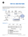
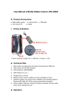
Figure 2.1 Terminal Block Locations
TB1
TB2
TB3
TE
Power Terminal Block
Control & Signal Wiring
Control Interface Option
Control & Signal Shield Terminals
Control Interface
Option
TB3
TB1
TB2
TB1
Frames A1-A4
!
Control Interface Option
ATTENTION: The National Electrical Code (NEC) and local
codes outline provisions for safely installing electrical
equipment. Installation must comply with specifications
regarding wire types, conductor sizes, branch circuit protection
and disconnect devices. Failure to do so may result in personal
injury and/or equipment damage.
The Control Interface Option provides a means of interfacing various
signals and commands to the 1336 PLUS II by using contact closures.
Nine different versions of the option are available:
L4
Contact Closure Interface 1
L4E
L5
L5E
L6
L6E
L7E
L8E
L9E
Contact Closure Interface with Encoder Feedback Inputs 1
24V AC/DC
24V AC/DC & Encoder Feedback
115V AC
115V AC & Encoder Feedback
TTL Contact & Encoder Fdback for use with Encoder Loss Detection
24V AC/DC & Encoder Fdback for use with Encoder Loss Detection
115V AC & Encoder Feedback for use with Encoder Loss Detection
1
Uses internal +5V DC supply.
The user inputs are connected to the option board through TB3. The L4 thru
L9 options each have nine control options. The function of each input must
be selected through programming as explained later in this chapter. The
L4E, L5E and L6E options are similar to L4, L5 and L6 with the addition of
encoder feedback inputs.
1336 PLUS - 6.16 - September, 2001
Control Logic Wiring and Adapters
Control Interface Board
Jumpers
2-3
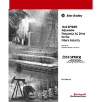
IMPORTANT: If the Control Interface Board is being installed, Main
Control Board Jumpers at pins 3 & 4 and 17 & 18 of J2 must be removed
and the proper [Input Mode] selected. If this board is removed, these
jumpers must be reinstalled and the [Input Mode] parameter must be
programmed to “Status (1).”
Figure 2.2 Jumper Locations
J2
3
J1
L
E
S
1
J1
C
S
E
J8
G
JO
Frames1 A1 - A4
1 Refer
Digital Inputs
to page 1–1 for frame reference classifications.
Digital Inputs are connected at TB3.
Input Mode Select
A number of combinations are available by first programming [Input Mode]
to the desired control scheme (i.e. 2 wire, 3 wire or Status). The remaining
inputs can then be configured by programming [TB3 Term 22 Sel] through
[TB3 Term 28 Sel]. Refer to the Digital I/O parameter group in Chapter 6 of
the PLUS II User Manual for programming information.
1336 PLUS - 6.16 - September, 2001
2-4
Control Logic Wiring and Adapters
Figure 2.3 Digital I/O Default Settings - TB3.
Input Mode (Start/Stop Functions Only)
Status2
(Factory Default)
2-Wire Control
Single-Source Control
3-Wire Control
Single-Source Reversing
Input 1
19
Status
Run Forward
Start
Input 2
20
Stop/Fault Reset3
Stop/Fault Reset3
Stop/Fault Reset3
Factory Default Inputs
Common
Input 3
Common
21
Status Only
22
Default Mode
shown at right
is not active
when
[Input Mode]
is set to "Status"
Rev/For4
(Programmable)
Jog
(Programmable)
Auxiliary3
(Programmable)
Input 4
23
Input 5
24
Common
25
Input 6
26
Speed Select 31
(Programmable)
Input 7
27
Speed Select 21
(Programmable)
Input 8
28
Speed Select 11
(Programmable)
Common
29
Common
Input 9
30
Common
Enable3
Enable3
See Speed Select Table.
2
If this mode is selected, the status of all inputs can
be read at the [Input Status] parameter. However,
only “Stop/Fault Reset” and “Enable” will have
control function.
3
These inputs must be present (reprogram if
necessary) before drive will start.
Bit 0 of [Direction Mask] must = 1 to allow TB3
direction change/bipolar operation.
Requires "2 Wire" control selection for [Input
Mode].
[TB3 Term 22] must be programmed to "Run
Reverse."
Encoder B
31
Encoder NOT A
32
Encoder NOT B
33
Encoder A
34
+12V (200mA max.)
35
5
Encoder Common
36
6
Included on
L4E through L9E
Only
4
2-Wire Control Example
19
20
21
22
!
Run Forward
3-Wire Control Example
19
5
Stop/Fault Reset
3
20
21
Common
Run Reverse
(Not Programmable)
1
6
22
Start
Stop
Common
Rev/For (Default)
A hazard of personal injury from automatic restart exists with 2-wire control.
2-wire control uses maintained Run contacts that act as both Run (closed)
and Stop (open) devices. Opening the Stop contact (terminal 20) will stop the
drive. If this contact is reclosed, any fault will be reset. If a valid Start
command is still present, the drive will restart. Only use 2-wire control for
applications outlined in NFPA79, "Under Voltage Protection."
If a 3-wire device (i.e. HIM) is also used, pressing the HIM Stop key will also
stop the drive. Releasing the Stop key will clear any faults that are present,
but the drive will not restart without cycling the Start contact.
1336 PLUS - 6.16 - September, 2001
Control Logic Wiring and Adapters
2-5
The following table defines the input state of the Speed Select inputs for a
desired frequency source.
Table 2.A Speed Select Input State vs. Frequency Source.
Speed Select 3
Speed Select 2
Open
Open
Open
Open
Accessed through [Freq Select 2] parameter
Open
Closed
Open
Closed
Closed
Open
Closed
Open
Closed
Closed
Closed
Closed
Speed Select 1
Open
Closed
Open
Closed
Open
Closed
Open
Closed
Frequency Source
[Freq Select 1]
[Freq Select 2]
[Preset Freq 1]
[Preset Freq 2]
[Preset Freq 3]
[Preset Freq 4]
[Preset Freq 5]
[Preset Freq 6]
[Preset Freq 7]
Local Programming
For local programming and control information, refer to the 1336 PLUS II
User Manual.
Human Interface Module
For a complete description of the Human Interface Module (HIM) including
key descriptions, module removal and overall HIM operation refer to
Chapter 3 of the 1336 PLUS II User manual (1336 PLUS 5.3).
1336 PLUS - 6.16 - September, 2001
2-6
Control Logic Wiring and Adapters
This Page Intentionally Blank
1336 PLUS - 6.16 - September, 2001
Chapter
3
Troubleshooting and Error Codes
Chapter Objectives
This chapter helps you trace faults to field-replaceable components.
NOTE: On 1336 PLUS II A1 - A4 Frames, the only replaceable parts are the
Main Control Board and Fans.
Troubleshooting Overview
To troubleshoot a 1336 PLUS II Adjustable Frequency AC Drive, you need
a Range DVM, or VOM with a range capacity of at least 1000V.
IMPORTANT: All printed circuit boards, except the Main Control Board
assembly, are referenced to negative ground (-bus).
!
ATTENTION: Power circuits are optically isolated from
control driver circuits. Power circuit components are “floating”
with respect to “ground”. Use only approved methods of
isolating test equipment when making measurements in power
circuits.
ATTENTION: Some printed circuit boards and drive
components may contain hazardous voltage levels. Remove
power before you disconnect or reconnect wires, and before you
remove or replace fuses and circuit boards. Verify bus voltage by
measuring the voltage between +DC and -DC on Terminal Block
TB1. Do Not attempt to service the drive until the bus voltage has
discharged to zero volts.
ATTENTION: Potentially fatal voltages may result from
improper useage of oscilliscope and other test equipment. The
oscilliscope chassis may be at a potentially fatal voltage if not
properly grounded. We do not recommend use of an oscilliscope
to directly measure high voltages. Use an isolated measuring
device with a high voltage probe. Contact Allen-Bradley for
recommendations.
ATTENTION: To guard against equipment damage when
troubleshooting the drive, always check the following before
issuing a Start command:
– Set the Speed Reference to minimum.
– Select the proper motor-rotation direction.
– Disconnect the motor from its mechanical load.
3-2
Troubleshooting and Error Codes
!
ATTENTION: This assembly contains parts and
sub-assemblies that are sensitive to electrostatic discharge. Static
control precautions are required when servicing this assembly.
Component damage may result if you ignore electrostatic
discharge control procedures. If you are not familiar with static
control procedures, reference Allen-Bradley Publication
8000-4.5.2, Guarding Against Electrostatic Discharge, or any
other applicable ESD protection handbook.
Electrostatic Discharge
Precautions
Electrostatic Discharge generated by static electricity can damage the
complimentary metallic oxide semiconductor devices on various drive
boards. It is recommended that you perform these procedures to guard
against this type of damage when circuit boards are removed or installed.
• Wear a wrist type grounding strap that is grounded to the chassis.
• Attach the wrist strap before removing the new circuit board from the
conductive packet.
• Remove boards from the drive and immediately insert them into their
conductive packets.
Fault Descriptions
Fault Display
The LCD display is used to indicate a fault by showing a brief text
statement relating to the fault as shown in the following figure. The fault
will be displayed until “Clear Faults” is initiated or drive power is cycled. A
Series A (version 3.0) or Series B & up HIM will display a fault when it
occurs, no matter what state the display is in. In addition, a listing of past
faults can be displayed by selecting “Fault queue” from the Control Status
menu (See Chapter 3 of the 1336 PLUS II user manual for more
information). Refer to Table 3.A for a listing and description of the various
faults.
Figure 3.1 Fault Display
Clearing a Fault
When a fault occurs, the cause must be corrected before the fault can be
cleared. After corrective action has been taken, simply cycling drive power
will clear the fault. Issuing a valid Stop command from the HIM or Control
Interface option (TB3) will also clear a fault if the {Flt Clear Mode]
parameter is set to “Enabled”. In addition, a “Clear Faults” command can be
issued anytime from a serial device (if connected).
1336 PLUS - 6.16 - September, 2001
Troubleshooting and Error Codes
3-3
Contact Description
A schematic representation of contacts CR1-CR4 is shown in Figure 2-5 of
the 1336 PLUS II User Manual. When powered these contacts will change
state. For Example: During normal operating conditions (no faults present,
drive running), the CR3 contacts (default firmware setting) at TB2-13 & 14
are open, and the contacts at TB2-14 & 15 are closed. When a fault occurs,
the state of these contacts will change.
Table 3.A
1336 PLUS II Fault Descriptions
Name & Fault #
Adptr Freq Err
65
Auxiliary Fault
02
Bgnd 10ms Over
51
Bipolar Dir Flt
16
Blwn Fuse Flt
58
C167 Watchdog
17
Diag C Lim Flt
36
Drive -> HIM
DSP Checksum
37
DSP Comm Fault
27
DSP Protected
46
DSP Queue Fault
31
1336 PLUS II - 6.16 - September, 2001
Description
The SCANport adapter that was
the selected frequency reference
sent a frequency greater than
32767 to the drive.
The auxiliary input interlock is
open.
Action
Correct the problem that is causing the
SCANport adapter to send the illegal
frequency reference to the drive.
If Control Interface option is installed,
check TB3 connections. If not installed,
set [Input Mode] to “Status.”
Microprocessor loop fault. Occurs if Replace Main Control Board or comthe 10ms background task hasn’t plete drive as required.
been run in 15 ms.
3 Wire – Bi-polar input is the active a) Mask out direction control at bit 7 of
frequency reference and direction [Direction Mask]. b) Remove or mask
control is not possible.
other direction control sources.
2 Wire – Run Forward or Reverse Set bit 7 of [Direction Mask] to zero.
commands attempt direction control, but bi-polar input is not
masked from direction control.
If the difference between the com- Locate cause, replace fuse.
manded voltage and the measured voltage is greater than 1/8 of
rated voltage for 0.5 seconds, then
a fault will be issued indicating that
the bus fuse in 30 kW (40HP) & up
drives has blown.
Internal microprocessor fault.
If there is only one occurrence, reset
the fault and continue. If the fault continuously or frequently reoccurs, contact your local service representative or
replace the Main Control Board.
The drive output current has
Check [Cur Lim Trip En]. Check for
exceeded the hardware current
excess load, improper DC boost setlimit and the [Cur Lim Trip En]
ting, DC brake volts set too high or
parameter was enabled.
other causes of excess current.
Refer to Table 3B.
There was a breakdown in commu- Reset to factory defaults. Replace Main
nications between the DSP and
Control Board or Gate Driver Board.
main processors.
Refer to the “Description” and “Action” statements for C167 Watchdog (F17)
above.
Flash download included a new
Remove power from the drive. Install
DSP Main Block and J14 was not J14 per download kit instructions and
installed when power was restored. reapply power. When transfer is complete, remove power and J14.
Refer to the “Description” and “Action” statements for C167 Watchdog (F17)
above.
3-4
Troubleshooting and Error Codes
Name & Fault #
DSP Reset Fault
22
DSP Timeout Fault
28
EE Init Read
53
EE Init Value
54
EEprom Checksum
66
EEprom Fault
32
Encoder Loss
60
Fgnd 10ms Over
52
Ground Fault
13
Ground Warning
57
Hardware Trap
18
Description
Action
Power-up has been attempted with Check/verify wiring and contact operaan Open Stop contact or Closed
tion.
Start contact.
Refer to the “Description” and “Action” statements for C167 Watchdog (F17)
on page 3.3.
1. Gate Drive Bd. replacement (re- 1. Reset to factory defaults & cycle inquires re-initialization).
put power.
2. Trouble reading EEPROM dur- 2. Check all connections to Power/
ing initialization.
Driver Board. Replace board or complete drive as needed.
Stored parameter value out of
1. Reset to factory defaults & cycle input power.
range on initialization.
2. Check all connections to the Power/
Driver Bd. Replace the board or
complete drive as needed.
The checksum read from the
1. Reset to factory defaults & cycle input power.
EEPROM does not match the
checksum calculated from the
2. Check all wire and cable connections to the Power Driver Board.
EEPROM data.
Replace Power Driver Board or complete drive as required.
EEPROM is being programmed
Check all wire and cable connections
and will not write a new value.
to the Main Control Board. Replace
Main Control Board or complete drive
as required.
The drive has detected an error in Check encoder and wiring.
the encoder signals at TB3, terminals 31-36. The error could be due
to a:
1. Loss of 1 or more channels.
2. Loss of quadrature.
3. Loss of differential signal (A & A
NOT or B & B NOT were high at
the same time).
Microprocessor loop fault. Occurs if Replace Main Control Board or coma 10ms interrupt is pending before plete drive as required.
the current interrupt is complete.
A current path to earth ground in Check the motor and external wiring to
excess of 100A has been detected the drive output terminals for a
at one or more of the drive output grounded condition.
terminals. NOTE: If ground current
exceeds 220% of drive rated current, “Overcurrent Flt” may occur
instead of Ground Fault.
A current path to earth ground in Check the motor and external wiring to
excess of 2A has been detected at the drive output terminals for a
one or more of the drive output ter- grounded condition.
minals. See [Ground Warning].
Refer to the “Description” and “Action” statements for C167 Watchdog (F17)
on page 3.3.
1336 PLUS - 6.16 - September, 2001
Troubleshooting and Error Codes
Name & Fault #
Hertz Err Fault
29
Hertz Sel Fault
30
HIM -> Drive
Ill Prog Input
62
Input Phase Flt
49
Load Loss Flt
20
Loop Overrn Flt
23
Max Retries Fault
33
Motor Mode Flt
24
Motor Stall Fault
06
Motor Thermistor
15
1336 PLUS II - 6.16 - September, 2001
Description
This fault indicates that there is not
a valid operating frequency. It can
be caused by any of the following:
1. [Maximum Freq] is less than
[Minimum Freq].
2. Skip frequencies and skip bandwidth eliminate all operating
frequencies.
3. Analog input signal speed
reference has been lost. See
[Anlg Signal Loss] and
[4-20mA Loss Sel].
A frequency select parameter has
been programmed with an out of
range value.
3-5
Action
1. Check [Minimum Freq] and [Maximum Freq] parameters.
2. Check [Skip Freq 1], [Skip Freq 2],
[Skip Freq 3] and [Skip Freq Band]
parameters.
3. Check for broken wires, loose connections or transducer loss at analog
inputs.
Reprogram [Freq Select 1] and/or [Freq
Select 2] with a correct value. If problem persists, replace Main Control
Board or complete drive.
Refer to Table 3.B.
[Fault Data] = 98 – “3 Wire” is
Reprogram the digital inputs or select
selected as the [Input Mode] and “2 Wire” as the [Input Mode].
one or more digital inputs are programmed to “Run Reverse” (2 wire
action).
The DC bus ripple has exceeded 1. If the drive is operated on single-phase, the load derating level
the value in [Phase Loss Level].
has been exceeded.
2. Check incoming power for a missing
phase/blown fuse.
[Load Loss Detect] is set to
1. Verify connections between motor
and load.
“Enabled” and the drive output
torque current was below [Load
2. Verify level and time requirements or
disable [Load Loss Detect].
Loss Level] for a time period
greater than [Load Loss time].
An overrun of the 2.5ms control
Check all connections to the Main Conloop has occurred.
trol Board. Replace the board or complete drive as needed.
Drive unsuccessfully attempted to Check fault buffer for fault code requirreset a fault and resume running
ing reset. Correct the cause of the fault
for the programmed number of
and manually clear by pressing the
[Reset/Run Tries].
local Stop key or cycling the TB3 Stop
input.
A fault has been detected originat- Check all connections to the Control
ing from the Control Board.
Board. Replace the board or complete
drive as required.
Current remained over [Current
If the motor is drawing excessive curLimit] setting (parameter 36) for
rent (over [Current Limit] setting), the
more than 4 seconds.
motor load is excessive and will not
allow the drive to accelerate to set
speed. A longer accel time or a
reduced load may be required.
An analog option board with ther- 1. Verify that thermistor is connected.
mistor input is installed and the
2. Motor is overheated. Reduce load.
value at the terminals is less than 3. Thermistor is not present. Remove
60 ohms or greater than 3300
option board.
ohms.
3-6
Troubleshooting and Error Codes
Name & Fault #
Mult Prog Input
61
Neg Slope Fault
35
Open Pot Fault
09
Op Error Fault
11
Option Error
14
Overcurrent Flt
12
Description
A single source input function such
as Reverse/Forward (open=1st
function, closed=2nd function) has
been programmed to more than
one input or more than one “Run
Reverse” input.
Drive software detected a portion
of the volts/hertz curve with a negative slope.
An external pot is connected and
the common side of the pot is
open. The drive generates this fault
when the voltage between pot
leads is greater than 3.9V DC.
A SCANport device requests a
Read or Write of a data type not
supported. This will also occur if:
1. [Motor Type] is set to “Sync PM”
and [Stop Mode Used] is set to
“DC Brake”, or
2. [Motor Type] is set to “Sync Reluc” or “Sync PM” and [Speed
Control] is set to “Slip Comp”.
A slot A analog option board has
been installed in slot B
or
A slot B board has been installed in
slot A
Overcurrent is detected in instantaneous overcurrent trip circuit.
Overload Fault
07
Internal electronic overload trip.
Overspeed Fault
25
Overtemp Fault
08
Not functional at time of printing.
Overvolt Fault
05
DC bus voltage exceeded maximum value.
Phase U Fault
38
A phase to ground fault has been
detected between the drive and
motor in this phase.
A phase to ground fault has been
detected between the drive and
motor in this phase.
Phase V Fault
39
Heat sink temperature exceeds a
predefined value of 90° C
(195° F).
Action
Reprogram one or more of the inputs to
a different value.
Check drive programming.
1. [Base Voltage] parameter must be
greater than [Start Boost].
2. If the [DC Boost Select] parameter is
set to “Full Custom,” [Base Voltage]
must be greater than [Break Voltage]
and [Break Voltage] must be greater
than [Start Boost].
Check the external potentiometer circuit at TB2 for an open circuit.
Check programming.
Remove or relocate to proper slot.
Check for a short circuit at the drive
output or excessive load conditions at
the motor.
An excessive motor load exists. It must
be reduced such that drive output current does not exceed the current set by
the [Overload Amps] parameter.
Check for blocked or dirty heat sink
fins. Check that the ambient temperature has not exceeded 40° C (104° F).
Check fan.
Monitor the AC line for high line voltage
or transient conditions.
Bus overvoltage can also be caused by
motor regeneration. Extend the decel
time or install dynamic brake option.
Check the wiring between the drive and
motor. Check motor for grounded
phase.
Check the wiring between the drive and
motor. Check motor for grounded
phase.
1336 PLUS - 6.16 - September, 2001
Troubleshooting and Error Codes
Name & Fault #
Phase W Fault
40
Poles Calc Flt
50
Power Loss Fault
03
Power Mode Fault
26
Power Overload
64
Precharge Fault
19
Precharge Open
56
Prm Access Flt
34
Reprogram Fault
48
ROM or RAM Flt
68
1336 PLUS II - 6.16 - September, 2001
Description
A phase to ground fault has been
detected between the drive and
motor in this phase.
Generated if the calculated value
of [Motor Poles] is less than 2 or
greater than 32.
DC bus voltage remained below
85% of nominal for longer than
500ms. [Line Loss Fault] parameter
is set to “enabled.”
The internal power mode variable
received an incorrect value.
3-7
Action
Check the wiring between the drive and
motor. Check motor for grounded
phase.
Check [Motor NP RPM] and [Motor NP
Hertz] programming.
Monitor the incoming AC line for low
voltage or line power interruption.
Check all connections to the Control
Board. Replace the board or complete
drive as required.
Reduce load.
The drive rating of 150% for 1
minute has been exceeded.
The precharge device was open
See Chapter 1 for frame definitions.
20ms after the end of a line loss
1. Frames A1, A2, A3 - Check the precondition or the bus charging alarm
charge circuit. Replace the drive.
remains on for 20 seconds (pre2. Frame B - Check the precharge circharge did not complete).
cuit. Replace the Power Driver Bd. or
complete drive as required.
3. All larger frames - Check the precharge circuit. Replace the input
SCRs, SCR Firing Board, Power
Driver Board or complete drive as
needed.
The precharge circuit was comSee page 1–1 for frame definitions.
manded to close, but was detected 1. Frames A1, A2, A3 - Check the preto be open.
charge circuit. Replace the drive.
2. Frame B - Check the precharge circuit. Replace the Power Driver Bd. or
complete drive as required.
3. All larger frames - Check the precharge circuit. Replace the input
SCRs, SCR Firing Board, Power
Driver Board or complete drive as
needed.
A communication error occurred
Record the value in [Fault Data], then
between the microprocessor and reset the fault. If this fault occurs
the serial EEPROM or the DSP.
repeatedly, contact factory.
The drive was commanded to write 1. Clear the fault or cycle power to the
drive.
default values to EEPROM.
2. Program the drive parameters as
needed.
Important: If [Input Mode] has been
changed from its original value, power
must be cycled before the new value
will take affect.
Internal power-up ROM or RAM
Replace Control Board or complete
tests have not executed properly. drive as required.
3-8
Troubleshooting and Error Codes
Name & Fault #
Serial Fault
10
Shear Pin Fault
63
Sync Loss Fault
67
Temp Sense Open
55
Undervolt Fault
04
UV Short Fault
41
UW Short Fault
42
VW Short Fault
43
Description
Action
A SCANport adapter has been dis- 1. If no adapter was intentionally disconnected, check wiring to the
connected and the [Logic Mask] bit
SCANport adapters. Replace wiring,
for that adapter is set to “1.”
SCANport expander, SCANport
adapters, Main Control Board or
complete drive as required.
2. If an adapter was intentionally disconnected and the [Logic Mask] bit
for that adapter is set to “1”, this fault
will occur. To guard against this fault
occurring, set the [Logic Mask] bit for
the adapter to “0.”
3. Check HIM connection for proper
seating.
Programmed [Current Limit] amps Check load requirements and [Current
has been exceeded and [Shear Pin Limit] setting.
Fault] is enabled.
Not functional at time of printing.
Heat sink thermistor is open or
malfunctioning.
DC Bus voltage fell below the minimum value (388V DC at 460V AC
input). [Line Loss Fault] and [Low
Bus Fault] set to “enabled.”
Excessive current has been
detected between these two output
terminals.
Excessive current has been
detected between these two output
terminals.
Excessive current has been
detected between these two output
terminals.
Check thermistor and connections.
Monitor the incoming AC line for low
voltage or line power interruption.
Check the motor and external wiring to
the drive output terminals for a shorted
condition.
Check the motor and external wiring to
the drive output terminals for a shorted
condition.
Check the motor and external wiring to
the drive output terminals for a shorted
condition.
1336 PLUS - 6.16 - September, 2001
Troubleshooting and Error Codes
3-9
Table 3.B
HIM Upload/Download Errors
Fault Name
HIM -> Drive
Error Displayed Probable Cause
ERROR 1
The HIM calculated a checksum for the file to be
downloaded, then checked the EEPROM
checksum of the download. The checksums did
not match, indicating the file stored in the HIM is
invalid and the download was not successful.
ERROR 2
The number of parameters in the HIM file is
different than the number of parameters in the
drive file. The smaller of the two numbers is the
number of parameters downloaded. The last
downloaded parameter number is displayed.
ERROR 3
ERROR 4
ERROR 5
ERROR 6
Drive -> HIM
ERROR 1
1336 PLUS II - 6.16 - September, 2001
Action
Upload a valid, uncorrupted file from the
source drive and then repeat the download.
Verify that the correct file is being
downloaded to the correct drive, then press
the Enter key.
Manually reprogram the parameters whose
numbers are higher than the last number
downloaded or whose values were
incorrect.
None - Download not allowed.
The file in the HIM is for a different type of drive
than the drive to which it is connected (i.e. 1336
PLUS file to 1336 IMPACT drive). Downloads can
only occur between like drive types.
The value just transferred to the drive is an illegal Record the parameter number displayed
value (out of range, too high or too low) for the
and then press the Enter key to continue
parameter.
the download. Manually reprogram all
recorded parameters after the download is
complete.
The download was attempted while the drive was Stop the drive and repeat the download
running.
attempt.
The file in the HIM is for a different HP or voltage If the download is desired, press the Enter
key. If not desired, press the ESCape key to
drive than the drive to which it is connected (i.e.
1336 PLUS 10 HP file to 1336 PLUS 15 HP drive). end the download
The HIM calculated a checksum as the file was
Repeat the Upload.
uploaded and compared it to the HIM file
checksum stored after the upload. The checksums
did not match, indicating the upload was not
successful and the HIM file is now corrupted.
3-10
Troubleshooting and Error Codes
Table 3.C
Fault Code Cross Reference
Fault #
02
03
04
05
06
07
08
09
10
11
12
13
14
15
16
17
18
19
20
22
23
24
26
27
28
29
30
31
32
33
34
35
36
37
38
39
40
41
42
43
46
47
48
49
50
51
52
53
54
55
Display Name
Auxiliary Fault
Power Loss Fault
Undervolt Fault
Overvolt Fault
Motor Stall Fault
Overload Fault
Overtemp Fault
Open Pot Fault
Serial Fault
Op Error Fault
Overcurrent Flt
Ground Fault
Option Error
Motor Thermistor
Bipolar Dir Flt
C167 Watchdog
Hardware Trap
Precharge Fault
Load Loss Flt
DSP Reset Fault
Loop Overrn Flt
Motor Mode Flt
Power Mode Fault
DSP Comm Fault
DSP Timeout Fault
Hertz Err Fault
Hertz Sel Fault
DSP Queue Fault
EEprom Fault
Max Retries Fault
Prm Access Flt
Neg Slope Fault
Diag C Lim Flt
DSP Checksum
Phase U Fault
Phase V Fault
Phase W Fault
UV Short Fault
UW Short Fault
VW Short Fault
DSP Protected
Xsistr Desat Flt
Reprogram Fault
Input Phase Flt
Poles Calc Fault
Bgnd 10ms Over
Fgnd 10ms Over
EE Init Read
EE Init Value
Temp Sense Open
Reset/Run
Yes
Yes
Yes
Yes
Yes
Yes
Yes
No
No
No
Yes
No
No
No
No
No
No
No
No
Yes
Yes
Yes
Yes
No
No
No
No
No
No
No
No
No
No
No
No
No
No
No
No
No
No
No
No
No
No
Yes
Yes
No
No
No
Fault #
56
57
58
60
61
62
63
64
65
66
67
68
Display Name
Precharge Open
Ground Warning
Blwn Fuse Flt
Encoder Loss
Mult Prog Input
Ill Prog Input
Shear Pin Fault
Power Overload
Adptr Freq Err
EEprom Checksum
Sync Loss Fault
ROM or RAM Flt
Reset/Run
No
No
No
No
No
No
No
No
No
No
No
No
Note: Fault Numbers not listed are reserved for future use.
1336 PLUS - 6.16 - September, 2001
Troubleshooting and Error Codes
Diagnostic Procedures by
Symptom
These charts list drive symptoms, symptom descriptions, and recommended
actions to remedy the symptoms.
Drive Will Not Start
Drive will not start
Display on HIM?
No
Refer to “No Display”
Yes
HIM displays
“Auxiliary Fault”?
Yes
Drive equipped
with L Option?
Yes
No
No
Drive equipped
with L Option?
Yes
Enable Input True?
No
Yes
Add a jumper to J2
between pins 3 & 4
or replace Main Control
Board as needed
Follow Instructions
given in Table 3.A
No
Drive running
at zero Hertz?
Yes
Refer to: “Drive
Stays at Zero Hertz
When Started”.
Yes
Are any bits in
{Stop Owner] set
to “1” ?
No
Does [Start Owner]
show a bit set to “1”
when START
commanded?
No
No
Find and corrrect source
of STOP command.
Correct Start Input
circuit or replace
Main Control Board
as needed.
Yes
Drive Starts?
Correct Auxiliary
Circuit and clear fault
Replace L Option or
Main Control Board?
No
HIM displays
“Stopped”
No
Yes
Yes
No
HIM displays
Fault Message?
Auxiliary Input True?
Yes
Program [Input Mode]
to “1” and cycle
input power
HIM displays
“Not Enabled”?
No
Replace Main
Control Board.
Yes
.
1336 PLUS II - 6.16 - September, 2001
3-11
End of troubleshooting
No
Correct Enable Circuit
3-12
Troubleshooting and Error Codes
No Display
No HIM display
Is the HIM backlight lit?
Yes
No
Is the drive’s fan
running?
No
Replace the HIM,
Main Control Board,
or Complete Drive as
needed.
Voltage present at
TB1-R, -S, -T?
Yes
HIM connected
properly?
Yes
Replace HIM,
Main Control Board,
or Complete Drive
as needed
No
Restore incoming
power to drive.
Yes
No
Re-connect HIM.
DC bus voltage
present?
Yes
Replace Complete
Drive
No
Replace Complete Drive
1336 PLUS - 6.16 - September, 2001
Troubleshooting and Error Codes
3-13
Drive Will Not Jog
Local Human Interface Module used to control drive.
Jog is not active if a START command is present. START command always
overrides a JOG command.
Drive will not Jog.
Is drive running?
Yes
No
No
Will drive run if
commanded to Start?
Drive must be
stopped before
attempting to Jog
Refer to “Drive Will
Not Start”.
Yes
Does a [Jog Owner]
bit go to 1 when Jog
is commanded?
No
Is the [Jog Mask] bit
for the adapter being
used set to 1 ?
Yes
No
Yes
No
Set the [Jog Mask]
bit for the adapter
being used to 1.
No
HIM displays
“Stopped” when Jog
is commanded?
Drive running at
incorrect frequency?
Is the Jog Input true
when Jog is
commanded?
External wiring problem
No
Replace Main
Control Board
Yes
Yes
Is a [Stop Owner] bit
set to 1?
Yes
Find and correct the
source of the Stop
command.
Yes
Change Logic Mask
bit to 1.
No
Is Logic Mask bit set
to 0?
No
Replace Main
Control Board
1336 PLUS II - 6.16 - September, 2001
Reprogram
[Jog Frequency].
Yes
Replace the Adapter
L Option, or Main
Control Board
3-14
Troubleshooting and Error Codes
Drive Stays at Zero Hertz When Started
IMPORTANT: [Command Frequency] parameter in the Metering Group
can be checked using the HIM.
Drive stays at Zero
Hertz when Started
{Drive Status]
Running Bit
(Bit1) = 1?
No
Refer to “Drive
Will Not Start”.
Yes
HIM displays “At Speed”
No
or [Drive Status] At
Speed Bit (Bit 8) = 1?
Yes
[Command Freq]
greater than zero?
Yes
HIM displays
“Accelerating” or
[Drive Status] Accel
Bit (Bit 4) = 1?
No
Replace Main Control
Board, or Drive as
needed.
Yes
Are [Accel Time 1] or
[Accel Time 2] set to
very long times?
Yes
Set [Accel Time 1] or
[Accel Time 2] to correct
application values.
No
No
[Drive Alarm] Motor Yes
Limit or Regen Limit
Bits (Bits 2 & 3) = 1?
Correct excessive
motor load condition
No
Is [Freq Source]
correct?
No
Yes
Is the frequency
reference input to the
drive at zero
No
Is [Input Mode] set
to a mode with L
Option TB3 Speed
Select inputs?
No
SCANport adapter has selected an
incorrect reference. Correct the
problem with, or replace, the
SCANport adapter.
Yes
Yes
Correct problem with
frequency reference.
Check state of Speed
Select inputs on TB3.
Check programming
of [Reference Mask]
and [ Input Mode].
Replace Main Control
Board or complete
drive as needed.
1336 PLUS - 6.16 - September, 2001
Chapter
4
Disassembly and Access Procedures
Chapter Objectives
This chapter describes general disassembly procedures required to remove
the Control Interface Board and Main Control Board on A1 to A4 frame
drives. Fan replacement is also detailed for A4 frame drives.
Disassembly and Access
Overview
!
ATTENTION: Some printed circuit boards and drive
components may contain hazardous voltage levels. Remove and
lock out power before you disconnect or reconnect wires, and
before you remove or replace fuses and circuit boards. Verify bus
voltage by measuring the voltage between +DC and -DC on
Terminal Block TB1. Do not attempt to service the drive until the
bus voltage has discharged to zero volts.
ATTENTION: Servicing energized industrial control
equipment can be hazardous. Electrical shock, burns, or
unintentional actuation of controlled industrial equipment may
cause death or serious injury. Follow the safety-related practices
of NFPA 70E, Electrical Safety for Employee Workplaces, when
working on or near energized equipment. Do not work alone on
energized equipment.
Electrostatic Discharge
Precautions
!
ATTENTION: This assembly contains parts and
sub-assemblies that are sensitive to electrostatic discharge. Static
control precautions are required when servicing this assembly.
Component damage may result if you ignore electrostatic
discharge control procedures. If you are not familiar with static
control procedures, reference Allen-Bradley Publication
8000-4.5.2, Guarding Against Electrostatic Discharge, or any
other applicable ESD protection handbook.
Electrostatic Discharge generated by static electricity can damage the
complimentary metallic oxide semiconductor devices on various drive
boards. It is recommended that you perform these procedures to guard
against this type of damage when circuit boards are removed or installed.
• Wear a wrist type grounding strap that is grounded to the chassis.
• Attach the wrist strap before removing the new circuit board from the
conductive packet.
• Remove boards from the drive and immediately insert them into their
conductive packets.
1336 PLUS II - 6.16 - June, 2001
4-2
Disassembly and Access Procedures
Tools
You need the following tools to disassemble and assemble the drive:
•
•
•
•
Disassembly and Access
Procedures
Pliers
#2 Phillips and a magnetic flat blade screwdriver
5/16 - inch or 8mm socket.
Torque wrench, metered in lb-in. or N-m
Drive Enclosure Removal & Installation
!
!
1336 PLUS - 6.16 - September, 2001
ATTENTION: Disconnect and lock out power from the drive
before disassembling the drive. Failure to disconnect power may
result in death or serious injury. Verify bus voltage by measuring
the voltage between +DC and -DC on Terminal Block TB1. Do
not attempt to service the drive until the bus voltage has
discharged to zero volts.
ATTENTION: Wear a wrist type grounding strap when
servicing 1336 PLUS II Drives. Failure to protect drive
components against ESD may damage drive components. Refer
to Electrostatic Discharge Precautions at the beginning of this
chapter.
Disassembly and Access Procedures
4-3
Removal
Figure 4.1
Removing the Drive Enclosure .
Enclosure Frame Mounting Screws
(4 Places)
Enclosure Cover
Cover Mounting Screw
Removal Sequence
1. Remove power from the drive.
2. Remove the screw fastening the Enclosure cover to the Enclosure frame.
3. Pull the bottom of the cover outward to clear the Enclosure frame, then
pull the cover down off the upper slots to remove.
4. Remove the four screws from the Enclosure frame top (2 screws) and
bottom(2 screws) panels and slide panels down out of engagement slots
on side panels. Remove side panels by sliding up off engagement tabs.
5. Check for zero volts at TB1 terminals +DC and -DC.
6. Check for the absence of control voltage before servicing the drive.
Installation
Install the Enclosure in reverse order of removal.
!
ATTENTION: Replace all guards before applying power to the
drive. Failure to replace guards may result in death or serious
injury!
1336 PLUS - 6.16 - September, 2001
4-4
Disassembly and Access Procedures
Removing Control Interface Board MOD - L4 - L9
Figure 4.2
Control Interface Board. (A Frame Drives)
J2
3
J1
L
E
S
1
J1
C
S
E
J8
G
JO
Frames1 A1 - A4
1 Refer
to page 1–1 for frame reference classifications.
Removal (A Frame Drives)
!
!
ATTENTION: Disconnect and lock out power from the drive
before disassembling the drive. Failure to disconnect power may
result in death or serious injury. Verify bus voltage by measuring
the voltage between +DC and -DC on Terminal Block TB1. Do
not attempt to service the drive until the bus voltage has
discharged to zero volts.
ATTENTION: Wear a wrist type grounding strap when
servicing 1336 PLUS Drives. Failure to protect drive components
against ESD may damage drive components. Refer to
Electrostatic Discharge Precautions at the beginning of this
chapter.
1. Remove power from the drive.
2. Remove the Enclosure cover if the drive has an enclosure. Refer to
removing the Drive Enclosure in this chapter.
3. Check for zero volts at TB1 terminals +DC and -DC.
4. Check for absence of control voltage.
5. Remove all wires from terminals on TB3
6. Loosen the two captive screws fastening the Control Interface Board to
the Main Control Board.
7. Grip the right and left sides of the Control Interface Board and pull the
board straight outward from the Main Control Board.
1336 PLUS - 6.16 - September, 2001
Disassembly and Access Procedures
4-5
Installation
1. Position the Control Interface Board over the J2 and J4 connectors with
the Terminal Block TB3 oriented on the left side of the drive with the
drive facing up.
2. Push the Control Interface Board straight down onto the J2 & J4
connectors. Tighten the two captive screws holding the Interface Board
to the Main Control Board.
3. Reinstall all wires previously removed at TB3.
4. Reinstall the enclosure cover before re-applying power to the drive.
!
ATTENTION: Replace all guards before applying power to the
drive. Failure to replace guards may result in death or serious
injury.
1336 PLUS - 6.16 - September, 2001
4-6
Disassembly and Access Procedures
Removing the Main Control Board
Removal (A Frame Drives)
Figure 4.4
Main Control Board Components (A Frame).
Main Control
Board
Connector
J1
Terminal Strip
TB 1
Stand-Of
Terminal Strip
TB 3
(7 places)
Terminal Strip
TB2
Mounting
Screw
(7 Places)
!
!
ATTENTION: Disconnect and lock out power from the drive
before disassembling the drive. Failure to disconnect power may
result in death or serious injury. Verify bus voltage by measuring
the voltage between +DC and -DC on Terminal Block TB1. Do
Not attempt to service the drive until the bus voltage has
discharged to zero volts.
ATTENTION: Wear a wrist-type grounding strap when
servicing 1336 PLUS II Drives. Failure to protect drive
components against ESD may damage drive components. Refer
to Electrostatic Discharge Precautions at the beginning of this
chapter.
IMPORTANT: Before you remove connections and wires from the drive
components, mark the connections and wires to correspond with their
component connections and terminals to prevent incorrect wiring during
assembly.
1336 PLUS - 6.16 - September, 2001
Disassembly and Access Procedures
4-7
1. Remove the Enclosure cover if the drive has an enclosure. Refer to
removing the Drive Enclosure in this chapter.
2. Remove power from the drive.
3. Check for zero volts at TB1 Terminals +DC and -DC
4. Check for the absence of control voltage.
Figure 4.5
Option Board Locations. (A Frame)
Analog Option Board
(Slot A)
Control Interface Option
J9, J10
J8, J11, J13
J9
I/O
OG A
AL
AN SLOT
8
7
5
3
6
4
2
1
I/O
OG B
AL
AN SLOT
J10
8
7
5
3
6
4
2
1
Slot B
Frames A1 - A4
5. Remove the Control Interface Board (L Option), if used. If a Control
Interface Board is not present, and a new Main Control Board will be
installed, the jumpers at pins 3 & 4 and 17 & 18 of J2 must be transferred
to the same location on the new board.
6. If a HIM (or other snap-in module) is installed, remove it by carefully
squeezing the locking tabs in and pulling the HIM straight out. Remove
the HIM cradle by removing the four screws securing it to the Main
Control Board.
7. If a new Main Control Board will be used, and a Communications
Option (1336-GM1, etc.) is installed in the Adapter 6 location it must be
removed and reinstalled on the new Main Control Board.
8. If a new Main Control Board will be used, and an Analog Interface
Board (LA1, LA2 etc.) is installed in Slot A or B, it must be transferred
to the new board. Note placement of the Analog Interface Board and
carefully remove the board by releasing standoffs and lifting straight out.
Transfer this board (and standoffs, if needed) to the same slot on the new
board. Repeat if a second board is present
9. Locate jumpers J8, J11 and J13. Note jumper placement - then transfer
jumpers to the same location on the new Main Control Board (if used).
10.Remove the communications connector at J3, the ribbon cable at J1 and
all wires at TB2.
11.Remove the six remaining screws (1 was previously removed with the
HIM cradle) holding the Main Control Board to the standoffs. Remove
the Main Control Board.
1336 PLUS - 6.16 - September, 2001
4-8
Disassembly and Access Procedures
Installing the Main Control Board
Installation (A Frame Drives)
1. Position the Main Control Board on the standoffs and install the six
screws that were previously removed in step 11 of disassembly. Torque
screws to 26 in-lb (3 N-m).
2. Install the HIM cradle to the Main Control Board with four screws.
3. Reinstall the communications connector at J3, the ribbon cable at J1 and
all wires at TB2.
4. Reinstall the Control Interface Board on the Main Control Board.
5. Install the HIM in the HIM cradle.
NOTE: Verify that the Analog Option Board(s) are correctly installed in the
proper slot for your application. The terminal designations at TB2 change
based on the Analog Option board installed and on slot location. Refer to
Publication 1336 PLUS-5.70 if you have questions on Analog Option Board
installation and set up.
6. Apply power - if a fault occurs, “Reset Defaults”. Download parameters
(if previously uploaded) from the HIM.
Gate Driver/Power Supply/Precharge Board
IMPORTANT: Individual components such as Bridge Rectifiers and
Transistor Modules cannot be tested or replaced separately as they are part
of the Gate Driver/Power Supply Board assembly.
If you suspect a problem on the Gate Driver/Power Supply Board, the Drive
should be returned to the factory for repair or replacement.
1336 PLUS - 6.16 - September, 2001
Disassembly and Access Procedures
4-9
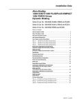
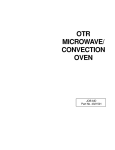
Removing the Fan Assemblies (A4 Frame Drives)
1.
2.
3.
4.
5.
Remove power from the drive.
Remove the Enclosure cover if the drive has an enclosure.
Check for zero volts at TB1 Terminals +DC and -DC
Check for the absence of control voltage before beginning fan removal.
Disconnect the fan leads at the J2 connector on the Main Control Board
(Figure 4.6). Cut any tie wraps fastening the fan leads to the drive frame.
6. Remove the four phillips head screws holding each fan unit and safety
shield to the heat sink. Withdraw each fan unit while threading the fan
leads down from the top layer of the drive.
Figure 4.6
Fan Assemblies (A4 Frame).
Installing Fan Assemblies (A4 Frame Drives)
1. Make certain power is removed from the drive.
2. Begin to thread the leads on the replacement fan units up thru the
opening to the first layer of the drive.
3. Position each fan unit with safety shield on the heat sink and install the
four screws thru the shields and the fans into the threaded holes on the
heat sink as shown in Figure 4.6. Tighten all screws securely.
4. Install the fan leads at terminal J2 and reroute and fasten the leads in the
same location as the previous unit.
5. Install all covers and re-power the drive.
1336 PLUS - 6.16 - September, 2001
4-10
Disassembly and Access Procedures
1336 PLUS - 6.16 - September, 2001
To contact Drives Technical Support . . .
Tel: (1) 262 512-8176, Fax: (1) 262 512-2222
Email: [email protected], Online: www.ab.com/support/abdrives
www.rockwellautomation.com
Corporate Headquarters
Rockwell Automation, 777 East Wisconsin Avenue, Suite 1400, Milwaukee, WI, 53202-5302 USA, Tel: (1) 414.212.5200, Fax: (1) 414.212.5201
Headquarters for Allen-Bradley Products, Rockwell Software Products and Global Manufacturing Solutions
Americas: Rockwell Automation, 1201 South Second Street, Milwaukee, WI 53204-2496 USA, Tel: (1) 414.382.2000, Fax: (1) 414.382.4444
Europe: Rockwell Automation SA/NV, Vorstlaan/Boulevard du Souverain 36-BP 3A/B, 1170 Brussels, Belgium, Tel: (32) 2 663 0600, Fax: (32) 2 663 0640
Asia Pacific: Rockwell Automation, 27/F Citicorp Centre, 18 Whitfield Road, Causeway Bay, Hong Kong, Tel: (852) 2887 4788, Fax: (852) 2508 1846
Headquarters for Dodge and Reliance Electric Products
Americas: Rockwell Automation, 6040 Ponders Court, Greenville, SC 29615-4617 USA, Tel: (1) 864.297.4800, Fax: (1) 864.281.2433
Europe: Rockwell Automation, Brühlstraße 22, D-74834 Elztal-Dallau, Germany, Tel: (49) 6261 9410, Fax: (49) 6261 17741
Asia Pacific: Rockwell Automation, 55 Newton Road, #11-01/02 Revenue House, Singapore 307987, Tel: (65) 351 6723, Fax: (65) 355 1733
U.S. Allen-Bradley Drives Technical Support
Tel: (1) 262.512.8176, Fax: (1) 262.512.2222, Email: [email protected], Online: www.ab.com/support/abdrives
Publication 1336 PLUS 6.16 – September, 2001
P/N 188749 (01)
Copyright 2001 Rockwell International Corporation. All rights reserved. Printed in USA