1
1336 PLUS II Quick Start Guide
This Quick Start Guide summarizes the basic steps needed to install, start-up and program the 1336 PLUS II Adjustable
Frequency AC Drive. The information provided Does Not replace the User Manual and is intended for qualified drive service
personnel only. Refer to the 1336 PLUS II User Manual (publication 1336 PLUS-5.3) for details on other application
considerations and related precautions.
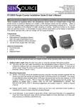
Power Wiring – TB1
TE
Ground
TE
AC Input
to Drive
R
(L1)
S
(L2)
PE
Ground
T
(L3)
PE
Drive Output
to Motor
PE
U
(T1)
V
(T2)
Dynamic Brake
W
(T3)
DC
+
DC
–
BRK
–
(Not on all drives)
(Not on all drives)
Required
Input Fusing
Common Mode Core*
Required Branch
Circuit Disconnect
Shield
Conduit/4-Wire Cable
* Optional
Motor
Terminator*
Motor Frame
PE
Ground per
Local Codes
Important: Verify motor insulation system peak voltage
rating. For cable lengths greater than 6.1
meters (20 feet), consult the User Manual.
Nearest
Building Structure Steel
Diagram shows connections that are common for all drives.
Refer to User Manual for Detailed Information.
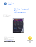
Digital Outputs – TB2
CR1
CR3
CR2
CR3
CR4
CR4
Only Present
on B Frame
& Up Drives
10
11
12
13
14
15
16
17
18
A1
A2
Contacts Shown in Unpowered State
(or Powered State with Fault/Alarm Present)
Terminal
TE
10, 11
11, 12
13, 14
14, 15
16, 17
17, 18
A1, A2
Signal
True Earth - Shield Termination
CR1 Programmable Contact
CR2 Programmable Contact
Resistive Rating = 115V AC/30V DC, 5.0A
CR3 Programmable Contact Inductive Rating = 115V AC/30V DC, 2.0A
Reserved for
Future Use
CR4 Programmable Contact
Reserved for Future Use
Important: On A Frame Drives, the power supply used for relay contact outputs requires a field installation of
transient voltage surge suppression with maximum clamping voltage of 2.5 kV on all control boards.
Publication 1336 PLUS-5.9ML – June, 2003
Supersedes January, 2002
P/N 188747 (06)
Copyright © 2003 Rockwell Automation, Inc. All rights reserved. Printed in USA.
1336 PLUS II Quick Start Guide
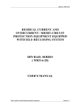
Digital Inputs – TB3
A hazard of personal injury from automatic restart exists
with 2-wire control. 2-wire control uses maintained Run
contacts that act as both Run (closed) and Stop (open)
devices. Opening the Stop contact (terminal 20) will stop
the drive. If this contact is reclosed, any fault will be reset.
If a valid Start command is still present, the drive will
restart. Only use 2-wire control for applications outlined in
NFPA79, "Under Voltage Protection."
If a 3-wire device (i.e. HIM) is also used, pressing the HIM
Stop key will also stop the drive. Releasing the Stop key
will clear any faults that are present, but the drive will not
restart without cycling the Start contact.
!
Speed Select Input State vs. Frequency Source
Speed Select 3 Speed Select 2 Speed Select 1
Open
Open
Open
Open
Open
Closed
Accessed through [Freq Select 2] parameter
Open
Closed
Open
Open
Closed
Closed
Closed
Open
Open
Closed
Open
Closed
Closed
Closed
Open
Closed
Closed
Closed
Frequency Source
[Freq Select 1]
[Freq Select 2]
[Preset Freq 1]
[Preset Freq 2]
[Preset Freq 3]
[Preset Freq 4]
[Preset Freq 5]
[Preset Freq 6]
[Preset Freq 7]
Important: The final speed command may be affected by the type of
modulation selected with [Speed Control], parameter 77.
Refer to [Speed Control] in Chapter 6 of the User Manual for
further information.
Differential Encoder Output
Connections Shown
Refer to User Manual
for
Single-Ended Connections
Input Mode (Start/Stop Functions Only)
Status2
(Factory Default)
2-Wire Control
Single-Source Control
3-Wire Control
Single-Source Reversing
Input 1
19
Status
Run Forward
Start
Input 2
20
Stop/Fault Reset3
Stop/Fault Reset3
Stop/Fault Reset3
Factory Default Inputs
Common
21
Input 3
22
Common
Status Only
Default Mode
shown at right
is not active
when
[Input Mode]
is set to "Status"
Rev/For4
(Programmable)
Jog
(Programmable)
Auxiliary3
(Programmable)
Input 4
23
Input 5
24
Common
25
Input 6
26
Speed Select 31
(Programmable)
Input 7
27
Speed Select 21
(Programmable)
Input 8
28
Speed Select 11
(Programmable)
Common
29
Common
Input 9
30
Encoder B
31
Encoder NOT A
32
Encoder NOT B
33
Encoder A
34
+12V (200mA max.)
35
Encoder Common
36
Common
Enable3
Included on
L4E through L9E
Only
Enable3
1
See Speed Select Table.
2
If this mode is selected, the status of all inputs can
be read at the [Input Status] parameter. However,
only “Stop/Fault Reset” and “Enable” will have
control function.
3
These inputs must be present (reprogram if
necessary) before drive will start.
Bit 0 of [Direction Mask] must = 1 to allow TB3
direction change/bipolar operation.
4
Recommended Cable (or equivalent):
Belden 9730 for distances less than 30 meters (98 feet)
Belden 9773 for distances greater than 30 meters (98 feet)
to TE
Jumper Locations
Connector J9
Connector J10
TB2-4
Common
TB2-9
Common
TB2-3
Input 1
TB2-8
Output 1
TB2-2
Input 0
TB2-7
Output 0
TB2-1
Pot Ref. (5V)
TB2-6
Input 2
Text Does Not Appear on Board
(for explanation purposes only)
Remaining Pins
Not Shown
Text Does Not Appear on Board
(for explanation purposes only)
Remaining Pins
Not Shown
J8, J11, J13
J9, J10
Slot A
J2
Slot B
J9
AN
A
SL LO
O G
T I/
A O
8
6
7
5
J9, J10
3
1
ES
J1
0
C
AN
A
SL LO
O G
T I/O
B
8
6
4
SE
2
7
J2
5
3
1
J8, J11, J13
JO
J9
8
AN
A
SL LO
O G
T I/
A O
6
7
5
3
1
J1
0
AN
A
SL LO
O G
T I/O
B
8
6
4
2
7
5
3
1
TB2
2
Slot A
Slot B
Frames A1 - A4
TB2
Frames B - G
(Not Programmable)
G
L
Analog I/O – TB2
Only Present
on B Frame
& Up Drives
TE
Signal
Common
TE
1
2
3
4
Std.
Pot.
Reference
+5V 1, 3
Single-Ended
Single-Ended
Signal
Input 0
Input 1
Common
Pot., 10V or 20mA Pot., 10V or 20mA
LA2
Isolated
Input 0 (+)
10V or 20mA
Isolated
Input 0 (–)
10V or 20mA
Isolated
Input 1 (+)
10V or 20mA
Isolated
Input 1 (–)
10V or 20mA
LA6
Isolated
Input 0 (+)
±10V, ±20mA
Isolated
Input 0 (–)
±10V, ±20mA
Thermistor
Isolated
Input (+)
Thermistor
Isolated
Input (–)
LA7
Isolated
Input 0 (+)
±10V, ±20mA
Isolated
Input 0 (–)
±10V, ±20mA
Isolated
Input 1 (+)
10V or 20mA
Isolated
Input 1 (–)
10V or 20mA
5
6
7
8
9
Std.
Single Ended Single Ended Signal
Single-Ended
Output 1
Common
Output 0
Input 2
0-10V Only
Pot., 10V or 20mA 0-10V Only
LA1
Single-Ended
Single-Ended Single-Ended 0-20mA
Input 2 2
Output 0
Output 1
Output
Pot., 10V or 20mA 10V or 20mA 20mA Only
Return
LA3
Isolated
Output 0 (+)
10V or 20mA
Isolated
Isolated
Isolated
Output 0 (–) Output 1 (+) Output 1 (–)
10V or 20mA 10V or 20mA 10V or 20mA
LA4
Isolated
Input 2 (+)
10V or 20mA
Isolated
Isolated
Isolated
Input 2 (–)
Output 1 (+) Output 1 (–)
10V or 20mA 10V or 20mA 10V or 20mA
LA5
Single-Ended
Output 0
10V or 20mA
Non-Isolated
250 kHz
Pulse Output
or (select 1)
or (select 1)
1 If an Option Board is installed in Slot A, the +5V pot. reference will not be
available. If a 5V source is required, it must be user supplied.
2 Standard Analog Input 2 is maintained at this terminal – configure with J11.
3 10k Ohm potentiometer required.
S
i
g
n
a
l
C
o
m
m
o
n
Analog I/O Option Slot A
Isolated
250 kHz
Pulse In (+)
Isolated
250 kHz
Pulse In (–)
Analog I/O Option Slot B
Start-Up
This start-up procedure covers only the most commonly adjusted values using the 1336 PLUS II “Startup” mode. Refer to the
User Manual for detailed information.
The following procedure is written for users who have a Human Interface Module (HIM) installed. For users without a HIM,
respective external commands and signals must be supplied. It is also assumed that all parameters are at factory default settings. Pay particular attention to steps marked with a “✔”.
!
ATTENTION: Power must be applied to the drive to perform the following. Some of the voltages present are at
incoming line potential. To avoid electric shock hazard or damage to equipment, only qualified drive service
personnel should perform the following procedure. Thoroughly read and understand the procedure before beginning.
If an event does not occur while performing this procedure, Do Not Proceed. Remove Power by opening the branch
circuit disconnect device and correct the malfunction before continuing.
!
ATTENTION: To avoid a hazard of electric shock when wiring or servicing the drive, verify that the voltage on the bus
capacitors has discharged. Measure the DC bus voltage at the + & – terminals of TB1. The voltage must be zero.
!
ATTENTION: To guard against possible machine damage and/or personal injury caused by unintended motor rotation,
Do Not press the Start key (HIM) or issue a Start command (TB3) during this Start-Up procedure until instructed to do
so. Pressing the Start key or issuing a Start command will cause the drive to start.
❑ 1. Verify that AC line power and control power match the drive rating.
Input Configuration (J8, J11, J13)
0-10V
J8 (TB2-2, Input 0)
(0-10V Configuration Shown)
Pot
❑ 4. If standard I/O is being used, verify that jumpers J8, J11 & J13 are properly set.
Refer to figure at right.
J13 (TB2-3, Input 1)
(Pot Configuration Shown)
Pot
✔ ❑ 3. If a Control Interface option is installed, verify that the Stop and Enable interlock
inputs are present. If this option is not installed, verify that jumpers are installed at
pins 3 & 4 and 17 & 18 of J2. In addition, [Input Mode] must be set to “Status.”
See page 2 for jumper locations.
Pot
✔ ❑ 2. Disconnect the load from the motor.
J11 (TB2-6, Input 2)
(0-20 mA Configuration Shown)
0-20 mA
0-10V
0-20 mA
0-10V
0-20 mA
1336 PLUS II Quick Start Guide
❑ 5. If Analog Option is installed, verify that DIP switch(es) are properly set (refer to Option Instruction Sheet).
ATTENTION: In all of the following steps, rotation of the motor may occur. To guard against injury, incorrect rotation
and possible equipment damage, read each step carefully and perform with caution.
!
❑ 6. Apply AC power and control voltages to the drive, the LCD display should light and display a drive status of
“Stopped” and an output frequency of “+0.00 Hz.” If the drive detects a fault, a statement relating to the fault will
be shown on the display – Record this information, remove power and correct the fault source before proceeding.
❑ 7. From the Status Display, press the Enter key (or any key). “Choose Mode” will be displayed. Press the Increment
(or Decrement) key until “Startup” is displayed. Press Enter.
Important: All questions can be answered Yes or No. Pressing Enter will select the default ("Y" or "N").
Pressing the Increment (or Decrement) key will change the selection - press Enter to select. Choosing
"Y" allows you to proceed through the step, "No" will advance you to the next step. The figure below
shows the steps involved.
Configure
Basic Setup
Configure Input
Voltage/Frequency
Enter Motor
Data
Enter
Encoder Data
Check Rotation
Verify Direction
Autotune
Configure
Digital I/O
Configure
Analog I/O
Enter Basic
Setup?
Modify Input
Volt/Freq?
Enter Nameplate
Motor Data?
Is an Encoder
Present?
Perform Motor
Rotation Test?
Autotune the
Motor?
Enter Digital
I/O Config?
Enter Analog
I/O Config?
Yes
Yes
[Accel Time 1]
[Decel Time 1]
[Overload Amps]
[Stop Select 1]
[Freq Select 1]
[Base Frequency]
[Maximum Freq]
[Base Voltage]
[Maximum Voltage]
Yes
[Motor NP Volts]
[Motor NP Amps]
[Motor NP Hertz]
[Motor NP RPM]
Yes
[Encoder Type]
[Encoder PPR]
Yes
Rotate Motor
Check Direction
Check Encoder Direction
(if present)
Yes
Compute Flux
Current &
IR Drop
See Important
statement below
Important: The Autotune routine is designed for use with standard induction motors only. It should not be used with synchronous motors.
Yes
Configure Inputs
[Input Mode]
[TB3 Term Sel]
Configure Outputs
[CR1-4 Out Select]
[Dig Out Freq]
[Dig Out Current]
[Dig Out Torque]
[Dig At Temp]
Yes
Configure Inputs
[Anlg In 0-2 Lo]
[Anlg In 0-2 Hi ]
[Anlg Signal Loss]
Configure Outputs
[Anlg Out 0-1 Sel]
[Anlg Out 0-1 Offset]
[Anlg Out 0-1 Abs]
[Anlg Out 0-1 Lo]
[Anlg Out 0-1 Hi]
Important: Please note the following:
• The “Startup” mode can be exited at any time by pressing ESCape until the Status Display is shown. If you wish
to re-enter the “Startup” mode, simply select “Reset Sequence” to start from the beginning. Selecting
“Continue” allows you to resume from the point where you left off.
• Completing the last action in any step will automatically take you to the next step.
• Pressing SELect will activate line 2 of the display – this must be done for all values.
• Press the Increment (or Decrement) key to adjust a value (skip if value is correct). Press Enter to store the value
or retain existing value. Pressing Enter again will cause you to move to the next step (parameter).
❑ 8. Remove all power, then reconnect load to motor. This completes the “Assisted Startup” procedure. Depending on
your application, further parameter programming and/or “Advanced Startup” may be required – refer to the User
Manual for details.
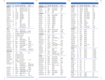
HIM Operation
Parameter programming (or viewing) is accomplished through the Program or Display modes as shown below.
a) From the Status Display, press Enter (or any key). “Choose Mode”
will be shown.
or
b) Press the Increment (or Decrement) key to show “Program” (or
“Display”).
c) Press Enter.
or
d) Press the Increment (or Decrement) key until the desired group is
displayed.
e) Press Enter.
or
f) Press the Increment (or Decrement) key to scroll to the desired
parameter.
4
1336 PLUS II Quick Start Guide
OPERATOR LEVEL
Power-Up Mode &
Status Display
ESC
or
SEL
or
or
or
MODE LEVEL
Not Available on Series A
HIMs (below Version 3.0)
Read Only
GROUP LEVEL
Process Display
Wraps to Linear List
Metering
Output Current (54)
Output Voltage (1)
Output Power (23)
DC Bus Voltage (53)
Output Freq (66)
Freq Command (65)
Anlg In 0 Freq (138)
Anlg In 1 Freq (139)
Anlg In 2 Freq (140)
Encoder Freq (63)
Pulse Freq (254)
MOP Freq (137)
Heatsink Temp (70)
Power OL Count (84)
Motor OL Count (202)
Last Fault (4)
Torque Current (162)
Flux Current (163)
% Output Power (3)
% Output Curr (2)
Elapsed Run Time (279)
Setup
Input Mode (241)
Freq Select 1 (5)
Accel Time 1 (7)
Decel Time 1 (8)
Minimum Freq (16)
Maximum Freq (19)
Stop Select 1 (10)
Current Limit (36)
Current Lmt Sel (232)
Adaptive I Lim (227)
Current Lmt En (303)
Overload Mode (37)
Overload Amps (38)
VT Scaling (203)
Motor NP RPM (177)
Motor NP Hertz (178)
Motor NP Volts (190)
Motor NP Amps (191)
PARAMETER LEVEL
5
Advanced
Setup
Frequency
Set
Minimum Freq (16)
Freq Select 1 (5)
Maximum Freq (19) Freq Select 2 (6)
PWM Frequency (45) Jog Frequency (24)
Accel Time 2 (30)
Preset Freq 1 (27)
Decel Time 2 (31)
Preset Freq 2 (28)
Sync Time (307)
Preset Freq 3 (29)
Stop Select 1 (10)
Preset Freq 4 (73)
DC Hold Time (12)
Preset Freq 5 (74)
DC Hold Level (13)
Preset Freq 6 (75)
Hold Level Sel (231) Preset Freq 7 (76)
Bus Limit En (11)
Skip Freq 1 (32)
Braking Chopper (314) Skip Freq 2 (33)
Motor Type (41)
Skip Freq 3 (34)
Stop Select 2 (52)
Skip Freq Band (35)
KP Amps (193)
MOP Increment (22)
Speed Brake En (319) 3 Save MOP Ref (230)
Freq Ref SqRoot (229)
Common Bus (58) 3
Pulse In Scale (264)
Encoder PPR (46)
Feature
Select
Digital
I/O
Analog
I/O
Anlg In 0 Lo (237)
Dwell Frequency (43) Input Mode (241)
Dwell Time (44)
TB3 Term 22 Sel (242) Anlg In 0 Hi (238)
Speed Control (77)
TB3 Term 23 Sel (243) Analog Trim En (90)
Slip @ F.L.A. (42)
TB3 Term 24 Sel (244) Anlg In 1 Lo (239)
Slip Comp Gain (195) TB3 Term 26 Sel (245) Anlg In 1 Hi (240)
Run On Power Up (14) TB3 Term 27 Sel (246) Anlg In 2 Lo (248)
Reset/Run Tries (85)
TB3 Term 28 Sel (247) Anlg In 2 Hi (249)
Reset/Run Time (15)
Anlg Signal Loss (250)
Input Status (55)
S Curve Enable (57)
CR1 Out Select (158) 4-20mA Loss Sel (150)
S Curve Time (56)
CR2 Out Select (174) Anlg Out 0 Sel (25)
Language (47)
CR3 Out Select (175) Anlg Out 0 Offst (154)
Flying Start En (155)
CR4 Out Select (176) Anlg Out 0 Abs (233)
FStart Forward (156)
Anlg Out 0 Lo (234)
Dig Out Freq (159)
FStart Reverse (157)
Dig Out Current (160) Anlg Out 0 Hi (235)
LLoss Restart (228)
Line Loss Mode (256) Dig Out Torque (161) Anlg Out 1 Sel (274)
Line Loss Volts (320)
Anlg Out 1 Abs (277)
Dig At Temp (267)
Loss Recover (321)
Anlg Out 1 Offst (278)
PI Max Error (293)
Ride Thru Volts (322) Pulse Out Select (280) Anlg Out 1 Lo (275)
Min Bus Volts (323)
Pulse Out Scale (281) Anlg Out 1 Hi (276)
Traverse Inc (78)
Pulse In Scale (264) Slot A Option (252)
Traverse Dec (304)
Slot B Option (253)
At Time (327) 3
Max Traverse (79)
Remote CR Output (326) 3
P Jump (80)
Bus Regulation (288)
Load Loss Detect (290)
Load Loss Level (291)
Load Loss Time (292)
Bus Reg Level 4/Max Bus Volts (325) 3
Faults
Diagnostics
Fault Buffer 0 (86)
Drive Status 1 (59)
Fault Buffer 1 (87)
Drive Status 2 (236)
Fault Buffer 2 (88)
Application Sts (316)
Fault Buffer 3 (89)
Drive Alarm 1 (60)
Clear Fault (51)
Drive Alarm 2 (269)
Cur Lim Trip En (82) Latched Alarms 1 (205)
Shear Pin Fault (226) Latched Alarms 2 (270)
Motor OL Fault (201)
Input Status (55)
Motor Therm Flt (268)
Freq Source (62)
Line Loss Fault (40)
Freq Command (65)
Blwn Fuse Flt (81)
Drive Direction (69)
Low Bus Fault (91)
Stop Mode Used (26)
Fault Data (207)
Flt Motor Mode (143) Motor Mode (141)
Flt Power Mode (144) Power Mode (142)
Fault Frequency (145) Output Pulses (67)
Current Angle (72)
Fault Status 1 (146)
Heatsink Temp (70)
Fault Status 2 (286)
Fault Alarms 1 (173) Set Defaults (64)
Fault Alarms 2 (287) DC Bus Memory (212)
Flt Clear Mode (39)
Meas. Volts (272)
Ground Warning (204) EEPROM Cksum (172)
Phase Loss Mode (330) 3
Phase Loss Level (331) 3
Precharge Fault (332) 3
Not Available on Series A
HIMs (below Version 3.0)
Not Available on Series A
HIMs (below Version 3.0)
Read Only
Save Values 2
Recall Values 2
Control Logic
Fault Queue
Reset Defaults
HIM -> Drive 1
Drive -> HIM 1
to Linear List & Metering
Ratings
Masks
Owners
Adapter I/O
Rated Volts (147)
Rated Amps (170)
Rated kW (171)
Firmware Ver. (71)
Cntrl Board Rev (251)
Rated CT Amps (148)
Rated CT kW (149)
Rated VT Amps (198)
Rated VT kW (199)
Drive Type (61)
Direction Mask (94)
Start Mask (95)
Jog Mask (96)
Reference Mask (97)
Accel Mask (98)
Decel Mask (99)
Fault Mask (100)
MOP Mask (101)
Traverse Mask (305)
Sync Mask (308)
Logic Mask (92)
Local Mask (93)
Alarm Mask 1 (206)
Alarm Mask 2 (271)
Stop Owner (102)
Direction Owner (103)
Start Owner (104)
Jog Owner (105)
Reference Owner (106)
Accel Owner (107)
Decel Owner (108)
Fault Owner (109)
MOP Owner (110)
Traverse Owner (306)
Sync Owner (309)
Local Owner (179)
Data In A1 (111)
Data In A2 (112)
Data In B1 (113)
Data In B2 (114)
Data In C1 (115)
Data In C2 (116)
Data In D1 (117)
Data In D2 (118)
Data Out A1 (119)
Data Out A2 (120)
Data Out B1 (121)
Data Out B2 (122)
Data Out C1 (123)
Data Out C2 (124)
Data Out D1 (125)
Data Out D2 (126)
Alt Type 2 Cmd (315)
1 Series B & Up Handheld HIM Only.
2 Reserved for Future Use
3 Firmware Version 3.001 & later
4 Firmware Version 4.001 & later
5 Firmware Version 5.001 & later
Login, Logout,
Modify
Process
Display
Process 1 Par (127)
Process 1 Scale (128)
Process 1 Txt 1 (129)
Process 1 Txt 2 (130)
Process 1 Txt 3 (131)
Process 1 Txt 4 (132)
Process 1 Txt 5 (133)
Process 1 Txt 6 (134)
Process 1 Txt 7 (135)
Process 1 Txt 8 (136)
Process 2 Par (180)
Process 2 Scale (181)
Process 2 Txt 1 (182)
Process 2 Txt 2 (183)
Process 2 Txt 3 (184)
Process 2 Txt 4 (185)
Process 2 Txt 5 (186)
Process 2 Txt 6 (187)
Process 2 Txt 7 (188)
Process 2 Txt 8 (189)
Encoder
Feedback
Speed Control (77)
Encoder Type (152)
Encoder PPR (46)
Maximum Speed (151)
Motor Poles (153)
Speed KI (165)
Speed KP* (164)
Speed Error (166)
Speed Integral (167)
Speed Adder (168)
Slip Adder (255)
Motor NP RPM (177)
Motor NP Hertz (178)
Encoder Counts (283)
Enc Count Scale (282)
Encoder Loss Sel (284)
Encoder Freq (63)
Max Enc Counts (328) 3
Process PI
Speed Control (77)
PI Config (213)
PI Status (214)
PI Ref Select (215)
PI Fdbk Select (216)
PI Reference (217)
PI Feedback (218)
PI Error (219)
PI Output (220)
KI Process (221)
KP Process (222)
PI Neg Limit (223)
PI Pos Limit (224)
PI Preload (225)
Motor
Control
Step Logic
Control Select (9)
SL0-6 Logic Step 5
Flux Amps Ref (192) SL0-6 Logic Jump 5
IR Drop Volts (194)
SL0-6 Step Setting 5
Flux Up Time (200)
SL0-6 Time 5
Start Boost (48)
SL0-6 Encoder Cnts 5
Run Boost (83)
Current Step 5
Boost Slope (169)
Break Voltage (50)
Break Frequency (49)
Base Voltage (18)
Base Frequency (17)
Maximum Voltage (20)
Run/Accel Volts (317)
Sync Loss Sel (310)
Sync Loss Gain (311)
Sync Loss Comp (313)
Sync Loss Time (312)
PWM Comp Time (333) 4
Break Freq (334) 4
PWM Break Freq (334) 5
Stability Gain (324) 4
Note: Parameters that appear in more than one group are shown in Bold – Parameter Numbers are shown in (parenthesis).
An asterisk (*) indicates that the parameter was not functional at time of printing.