1
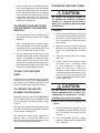
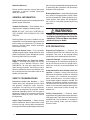
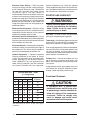
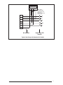
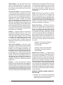
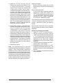
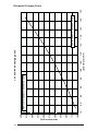
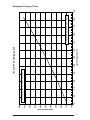
Outdoor Heat Pump
User’s Information and Installation Instructions
T3BN Series High Efficiency Commercial Split System
These units have been designed and tested for capacity and efficiency in accordance with A.R.I. Standards. Split System Heat Pump units, when combined with
our air handlers, offer a high quality, matched heating and cooling system.
These instructions are primarily intended to assist qualified individuals experienced in the proper installation of heating and/or air conditioning appliances.
Some local codes require licensed installation/service personnel for this type of
equipment. Read all instructions carefully before starting the installation.
OPERATING INSTRUCTIONS
TO OPERATE YOUR HEAT PUMP
FOR COOLING —
1. Set the thermostat system switch to COOL
and the thermostat fan switch to AUTO. (See
Figure 1)
2. Set the thermostat temperature to the desired
temperature level using the temperature
selector. Please refer to the separate
detailed thermostat user’s manual for
complete instructions regarding thermostat
programming. The outdoor unit and indoor
blower will both cycle on and off to maintain
the indoor temperature at the desired cooling
level.
2. Set the thermostat temperature to the
desired temperature level using the
temperature selector. Please refer to
the separate detailed thermostat user’s
manual for complete instructions regarding
thermostat programming. The outdoor unit
and indoor blower will both cycle on and off
to maintain the indoor temperature at the
desired heating level.
NOTE: If the thermostat temperature level is
re-adjusted, or the thermostat system switch
is repositioned, the outdoor unit may not
start immediately. The outdoor unit contains
a protective timer circuit which holds the unit
off for approximately five minutes following
a previous operation, or the interruption of
the main electrical power.
Emergency Heat:
NOTE: If the thermostat temperature level is
re-adjusted, or the thermostat system switch
is repositioned, the outdoor unit may not
start immediately. The outdoor unit contains
a protective timer circuit which holds the unit
off for approximately five minutes following a
previous operation, or the interruption of the
main electrical power.
TO OPERATE YOUR HEAT PUMP
FOR HEATING —
1. Set the thermostat system switch to HEAT
and the thermostat fan switch to AUTO. (See
Figure 1)
SYSTEM
MODE
The thermostat includes a system switch
position termed EM. HT. This is a back-up
heating mode to be used only if there is a
suspected problem with the outdoor unit.With
the system switch set to EM. HT. the outdoor
unit will be locked off, and supplemental heat
(typically electric resistance heating) will be
used as a source of heat. Sustained use of
electric resistance heat in place of the heat
pump will result in an increase in electric
utility costs.
Defrost:
During cold weather heating operation, the
outdoor unit may develop a coating of snow
and ice on the heat transfer coil. This is
FAN
SWITCH
Figure 1. Typical Thermostat
2
TEMPERATURE
SENSOR
normal, and the unit will periodically defrost
itself. During the defrost cycle, the outdoor
fan will stop, and the compressor will continue
to run and heat the outdoor coil, causing the
snow and ice to melt. After the snow and ice
have melted, some steam may rise from the
outdoor unit as the warm coil causes some
melted frost to evaporate.
TO OPERATE YOUR HEAT PUMP
FOR AUTOMATIC COOLING AND
HEATING—
1. Set the thermostat system switch to AUTO
and the thermostat fan switch to AUTO. (See
Figure 1)
Note: Thermostats will vary. Some models
will not include the AUTO mode, and others
will have the AUTO in place of the HEAT and
COOL, and some will include all three.
2. Set the thermostat temperature to the
desired heating and cooling temperature
level(s). The outdoor unit and the indoor
blower will then cycle on and off in either
the heating or cooling mode of operation as
required to automatically maintain the indoor
temperature within the desired limits.
TO SHUT OFF YOUR HEAT
PUMP—
Set the thermostat system switch to OFF and the
thermostat fan switch to AUTO. (See Figure 1)
The system will not operate, regardless of the
thermostat temperature selector(s) setting.
TO OPERATE THE INDOOR
BLOWER CONTINUOUSLY—
Set the thermostat fan switch to ON (See Figure
1). The indoor blower will start immediately, and
will run continually until the fan switch is reset
to AUTO.
The continuous indoor blower operation can be
obtained with the thermostat system switch set
in any position, including OFF.
The continuous indoor blower operation is
typically used to circulate the indoor air to
equalize a temperature unbalance due to a sun
load, cooking, or fireplace operation.
TO MAINTAIN YOUR HEAT PUMP—
CAUTION:
Be certain the electrical power to
the outdoor unit and the furnace/air
handler is disconnected before
doing the following recommended
maintenance.
1. Regularly:
a. Clean or replace the indoor air filter at the
start of each heating and cooling season,
and when an accumulation of dust and
dirt is visible on the air filter. Inspect the
filter monthly.
b. Remove any leaves and grass clippings
from the coil in the outdoor unit, being
careful not to damage the aluminum
fins.
c. Check for any obstruction such as twigs,
sticks, etc.
d. Certain models have external panels
fabricated from a premium grade
of steel designed to inhibit corrosion. For such units, if the unit is
located in a coastal region or other area
subjected to high concentrations of salt,
then the unit should be hosed off after
storms and monthly otherwise to maintain
its new appearance.
CAUTION:
Do not over-oil, or oil motors not
factory-equipped with oil tubes. The
compressor is hermetically “sealed”
and does not require lubrication.
2. Before Calling a Service Technician, Be
Certain:
a. The unit thermostat is properly set—see
“To Operate Your Heat Pump for Cooling”
and “To Operate Your Heat Pump for
Heating.”
b. The unit disconnect fuses are in good
condition, and the electrical power to the
unit is turned on.
3
Read Your Warranty
Please read the separate warranty document
completely. It contains valuable information
about your system.
GENERAL INFORMATION
Read the following instructions completely before
performing the installation.
the instructions provided with the equipment prior
to performing the installation and operational
checkout of the equipment.
Brazing Operations — Installation of equipment
may require brazing operations. Safety codes
must be complied with. Safety equipment (e.g.;
safety glasses, work gloves, fire extinguisher,
etc.) must be used when performing brazing
operations.
Outdoor Unit Section — Each outdoor unit is
shipped with a refrigerant holding charge.
NOTE: DO NOT USE ANY PORTION OF
THE CHARGE FOR PURGING OR LEAK
TESTING.
WARNING:
Ensure all electrical power to the unit
is off prior to installing or servicing the
equipment. Failure to do so may cause
personal injury or death.
Matching indoor coils and air handlers may be
shipped with a small holding charge to pressurize
them to keep out contaminants. To release the
pressure, read the indoor section installation
instructions carefully.
SITE PREPARATION
Liquid and Suction Lines — Fully annealed,
refrigerant grade copper tubing should be used
when installing the system. Refrigerant suction
line tubing should be fully insulated.
Unpacking Equipment — Remove the
cardboard carton and User’s Manual from the
equipment. Take care to not damage tubing
connections when removing from the carton.
Field Connections for Electrical Power
Supply — All wiring must comply with current
provisions of the “National Electrical Code”
(ANSI/NFPA 70) and with applicable local
codes having jurisdiction. The minimum size of
electrical conductors and circuit protection must
be in compliance with information listed on the
outdoor unit data label.
Inspect for Damage — Inspect the equipment
for damage prior to installing the equipment at
the job site. Ensure coil fins are straight and, if
necessary, comb fins to remove flattened and
bent fins.
SAFETY CONSIDERATIONS
Pressures within the System — Split
system heat pump equipment contains liquid
and gaseous refrigerant under pressure.
Installation and servicing of this equipment
should be accomplished by qualified, trained
personnel thoroughly familiar with this type of
equipment. Under no circumstances should the
Homeowner attempt to install and/or service
the equipment.
Labels, Tags, Precautions — When working
with this equipment, follow all precautions in the
literature, on tags, and on labels provided with
the equipment. Read and thoroughly understand
4
Preferred Location of the Outdoor Unit at the
Job Site — Conduct a survey of the job site to
determine the optimum location for mounting
the outdoor unit. Overhead obstructions,
poorly ventilated areas, and areas subject to
accumulation of debris should be avoided. The
outdoor unit should be installed no closer than
18 inches from the outside walls of the facility
and in an area free from overhead obstructions
to ensure unrestricted airflow through the
outdoor unit.
Facility Prerequisites — Electrical power
supplied must be adequate for proper operation
of the equipment. The system must be wired and
provided with circuit protection in accordance
with local building codes and the National
Electrical Code.
INSTALLING THE OUTDOOR UNIT
Slab Mount — The site selected for a slab mount
installation requires a stable foundation and one
not subject to erosion. The slab should be level
and anchored (if necessary) prior to placing the
equipment on the slab.
Cantilever Mount — The cantilever mount
should be designed with adequate safety factor
to support the weight of the equipment, and for
loads subjected to the mount during operation.
Installed equipment should be adequately
secured to the cantilever mount and levelled
prior to operation of the equipment.
Roof Mount — The method of mounting should
be designed so as not to overload roof structures
nor transmit noise to the interior of the structure.
Refrigerant and electrical line should be routed
through suitably waterproofed openings to
prevent water leaking into the structure.
INSTALLING THE INDOOR UNIT
The indoor section should be installed before
proceeding with routing of refrigerant piping.
Consult the Installation Instructions of the indoor
unit (i.e.: air handler, furnace, etc.) for details
regarding installation.
CONNECTING REFRIGERANT
TUBING BETWEEN THE INDOOR
AND OUTDOOR UNIT
General — Once outdoor and indoor unit
placement has been determined, route refrigerant
tubing between the equipment in accordance with
sound installation practices. Refrigerant tubing
should be routed in a manner that minimizes the
length of tubing and the number of bends in the
tubing. Refrigerant tubing should be supported
in a manner that the tubing will not vibrate or
abrade during system operation. Tubing should
be kept clean of foreign debris during installation
and installation of a liquid line filter drier is
recommended if cleanliness or adequacy of
system evacuation is unknown or compromised.
Every effort should be made by the installer
to ensure that the field installed, refrigerant
containing components of the system have been
installed in accordance with these instructions
and sound installation practices so as to insure
reliable system operation and longevity.
The maximum recommended interconnecting
refrigerant line length is 75 feet, and the
vertical elevation difference between the indoor
and outdoor sections should not exceed 20
feet. Consult long line application guide for
installations in excess of these limits.
Filter Dryer Installation — A filter dryer is
provided with the unit and installed inside the
outdoor unit.
Optional Equipment — Optional equipment
(e.g.: liquid line solenoid valves, etc.) should
be installed in strict accordance with the
manufacturer’s installation instructions.
ELECTRICAL CONNECTIONS
WARNING:
Turn off all electrical power at the main
circuit box before wiring electrical
power to the outdoor unit. Failure to
comply may cause severe personnel
injury or death.
Wiring Diagram/Schematic — A wiring
diagram/schematic is located on the inside cover
of the electrical box of the outdoor unit. The
installer should become familiar with the wiring
diagram/schematic before making any electrical
connections to the outdoor unit.
Outdoor Unit Connections — The outdoor
unit requires both power and control circuit
electrical connections. Refer to the unit wiring
diagram/schematic for identification and location
of outdoor unit field wiring interfaces.
Control Circuit Wiring — The outdoor unit is
designed to operate from a 24 VAC Class II control
circuit. Control circuit wiring must comply with
the current provisions of the “National Electrical
Code” (ANSI/NFPA 70) and with applicable local
codes having jurisdiction.
Thermostat connections should be made in
accordance with the instructions supplied with
the thermostat, and with the instructions supplied
with the indoor equipment. A typical commercial
installation with a heat pump thermostat and air
handler are shown on the next page.
5
Electrical Power Wiring — Electrical power
wiring must comply with the current provisions
of the “National Electrical Code” (ANSI/NFPA
70) and with applicable local codes having
jurisdiction. Use of rain tight conduit is
recommended. Electrical conductors shall have
minimum circuit ampacity in compliance with the
outdoor unit rating label. The facility shall employ
electrical circuit protection at a current rating no
greater than that indicated on the outdoor unit
rating label. Refer to the unit wiring diagram for
connection details.
Minimum Circuit Ampacity — Electrical wiring
to the equipment must be compatible and in
compliance with the minimum circuit ampacity
listed on the outdoor unit data label.
Maximum Fuse/Circuit Breaker Size — Circuit
protection for the outdoor unit must be compatible
with the maximum fuse/circuit breaker size listed
on the outdoor unit data label.
Disconnect Switch — An electrically compatible
disconnect switch must be within line of sight of
the outdoor unit. This switch shall be capable of
electrically de-energizing the outdoor unit.
Optional Equipment — Optional equipment
requiring connection to the power or control
circuits must be wired in strict accordance with
current provisions of the “National Electrical
Code” (ANSI/NFPA 70), with applicable local
codes having jurisdiction, and the installation
instructions provided with the equipment.
Optional Equipment (e.g.: liquid line solenoid
valves, refrigerant compressor crankcase heater,
etc.) should be installed in strict accordance with
the manufacturer’s installation instructions.
STARTUP AND CHECKOUT
WARNING:
Ensure electrical power to the unit is
off prior to performing the following
steps. Failure to do so may cause
personal injury or death.
Air Filters — Ensure air filters are clean and in
place prior to operating the equipment.
Thermostat — Set the room thermostat function
switch to OFF, fan switch to AUTO, and adjust the
temperature setpoint to its highest setting.
Prior to applying electrical power to the outdoor
unit, ensure that the unit has been properly and
securely grounded, and that power supply
connections have been made at both the facility
power interface and outdoor unit.
Outdoor Unit — Ensure the outdoor coil and
top of the unit are free from obstructions and
debris, and all equipment access/control panels
are in place.
Using extreme caution, apply power to the unit
and inspect the wiring for evidence of open,
shorted, and/or improperly wired circuits.
COPPER WIRE SIZE — AWG
(1% Voltage Drop)
Supply Wire Length-Feet
Supply Circuit
200
150
100
50
Ampacity
6
8
10
14
15
4
6
8
12
20
4
6
8
10
25
4
4
6
10
30
3
4
6
8
35
3
4
6
8
40
2
3
4
6
45
2
3
4
6
50
Wire Size based on N.E.C. for 60° type copper
conductors.
6
Functional Checkout:
CAUTION:
If equipped with a compressor
crankcase heater, wait 24 hours prior
to performing a function checkout to
allow for heating of the compressor
crankcase. Failure to comply may
result in damage and could cause
premature failure of the system.
Thermostat
G R W 2C E O Y
NOTE: Jumper
between W2 and E is
required when no OD
T-Stat is used.
C & W2 to be connected
to Electric Heat.
R
R
Y
Y
O
O
W1
W2
W2
C
C
G
Air Handler
Heat Pump OD
Section
Typical Heat Pump with Standard Air Handler
7
Indoor Blower — Set the thermostat function
switch to COOLING and the fan switch to ON.
Verify that the indoor blower is operating and
that airflow is not restricted. Set the fan switch
back to AUTO.
Low-Pressure Switch — A low-pressure switch
is factory-installed (see attached). This switch
is located in the suction line internal to the outdoor unit. The switch is designed to protect the
compressor from a loss of charge. Under normal
conditions, the switch is closed. If the suction
pressure falls below 5 psig, then the switch will
open and de-energize the outdoor unit. The
switch will close again once the suction pressure
increases above 20 psig. Please note that the
switch interrupts the thermostat inputs to the unit.
Thus, when the switch opens and then closes,
there will be a 5 minute short cycling delay before
the outdoor unit will energize.
Cooling — Gradually lower the thermostat
temperature setpoint below the actual room
temperature and observe that the outdoor unit
and indoor blower energize. Feel the air being
circulated by the indoor blower and verify that
it is cooler than ambient temperature. Listen
for any unusual noises. If present, locate and
determine the source of the noise and correct
as necessary.
Short Cycle Protection — With the system
operating in COOLING mode, note the setpoint
temperature setting of the thermostat, and
gradually raise the setpoint temperature until
the outdoor unit and indoor blower de-energize.
Immediately lower the setpoint temperature of
the thermostat to its original setting and verify
that the indoor blower is energized and that the
outdoor unit remains de-energized. Verify that,
after approximately 5 minutes, the outdoor unit
energizes and that the temperature of the air
supplied to the facility is cooler than ambient
temperature.
Heating — Lower the thermostat setpoint
temperature to the lowest obtainable setting and
set the thermostat function switch to HEATING.
The indoor blower and outdoor unit should stop
running. After a minimum of five minutes, increase
the setpoint temperature of the thermostat to the
maximum setting. Verify that the outdoor unit and
indoor blower have energized. Feel the air being
circulated by the indoor blower and verify that
it is warmer than ambient temperature. Listen
for any unusual noises. If present, locate and
determine the source of the noise and correct
as necessary.
NOTE: Other sources for heating (i.e.: electric
furnace, fossil fuel furnace, air handler with
electric heat options, etc.) that interface with
the unit should be functionally checked to verify
system operation and compatibility. Refer to the
installation instructions for this equipment and
perform a functional checkout in accordance
with the manufacturer’s instructions.
Defrost Cycle Timer — The defrost cycle timer
controls the accumulated run time interval of
the hot gas defrost after the defrost sensor
closes. It is located in the upper right corner of
the defrost control board. Three interval settings
are available: 30 minutes, 60 minutes, and 90
minutes. Time setting selection is dependent on
the climate where the unit is being installed. The
default defrost cycle timer is set to 30 minutes. To
adjust the cycle time, move the jumper to cover
the two pins directly adjacent to the desired
cycle time.
Example 1. Dry climate of Southern
Arizona. A 90 minute setting is
recommended.
Example 2. Moist climate of Seattle,
Washington. A 30 minute setting is
recommended.
High-Pressure Switch — A high-pressure
switch is factory-installed and located in the liquid
line internal to the outdoor unit. The switch is
designed to protect the system when very high
pressures occur during abnormal conditions.
Under normal conditions, the switch is closed.
If the liquid pressure rises above 425 psig, then
the switch will open and de-energize the outdoor
unit. The switch will close again once the liquid
pressure decreases to 350 psig. Thus, when the
switch opens and then closes, there will be a 5
minute short cycling delay before the outdoor
unit will energize.
DEFROST CONTROL BOARD OPERATION
AND TESTING
1. Terminals “R”-”C” must have 24±V present
between them in order for the time delay and
defrost sequences to be operational.
8
2. Jumper the “T2”-”DFT” test pins. This will
indicate to the board that the defrost T-stat
is closed(if the compressor is running).
Defrost T-stat is closed at 32° or below and
is open at 68° or above. But it’s state is
unknown if the temperature is between 32°F
and 68°F. The defrost thermostat tells the
board whether a defrost cycle needs to be
started or terminated. With the DFT closed
the unit will run for 30/60/90 minutes in heat
mode and then defrost the outdoor coil. The
defrost will turn off the outdoor fan, turn on the
compressor and raise the coil temperature to
68°F. This will open the DFT and terminate
the defrost. If the DFT does not open the
defrost will end after 10 minutes.
Speed up changes:
Manually initiating a defrost will cause the
compressor to run continually when entering
defrost.
3. Defrost board speed-up. With compressor
running in heat mode, next jump the “Test”
pin to “C” on terminal strip. This will initiate
a defrost test in 5, 10 or 15 seconds (This
is determined by the 30, 60 or 90 minute
defrost pin settings. The factory setting will
be 30 minutes). Note that this will bypass the
compressor off delay when the unit goes into
defrost test and if left in defrost test, the delay
will be bypassed when the test is terminated
by the processor. If the jumper is removed
before the test is over the processor will
perform the remainder of a normal defrost.
See step 2 above.
Note: If jumper is left on the “Test” to “common”
pins permanently, the defrost cycle will become
inoperable.
4. Remove the jumpers.
Note: The delay/no-delay pin concerns
compressor operation during defrosts.The default
setting is delay. Reciprocating compressors
should only use this setting in conjunction with
an approved hard start kit. Scroll compressors
that have noise issues while going into or coming
out of defrost should use this 30 second delay to
reduce the defrost noise.To switch from no-delay
to delay remove the pin from the “no-delay” pin
location and shift it to the “delay” pin location.
Normal defrost operation:
To test normal defrost operation when the
temperature is above 35°F, jumper “R” to
“DFT” on the 624656 board and allow the unit
to run for 30 minutes. Defrost will continue
until the “R” to “DFT” jumper is removed or
for 10 minutes. Remove the jumper.
The 5 minute time delay feature can be shortened
1 time to 1 second by jumping the “Test” to “C”
terminal. Remove the jumper and repeat as
desired.
Defrost Test Procedure for 624656
1. Jumper “T2” to “DFT” at the test terminals.
2. With unit running in heat mode, short the
“TEST” terminal to the common terminal near
it. This will speed up the board and cause
it to enter defrost mode in 5/10/15 seconds
depending on the defrost time selection.
Compressor delay will not function during
speed-up.
3. This test will end in 5 seconds if the “TEST”common short is not removed.
4. Remove both the short and the “T2” to “DFT”
jumper to terminate the defrost cycle. The
30 second compressor delay should operate
normally.
5. Test is complete, reset thermostat to home
owner preference.
9
10
150
175
200
225
250
275
300
325
350
375
400
75
80
85
90
95
Remove refrigerant when above curve
105
110
Liquid Temperature (F)
100
7.5 Ton HP TXV Charging Chart
115
120
125
130
Add refrigerant when below curve
135
Refrigerant Charging Charts
Liquid Pressure (psig)
Liquid Pressure (psig)
150
175
200
225
250
275
300
325
350
375
400
75
80
85
90
95
Remove refrigerant when above curve
105
110
Liquid Temperature (F)
100
10 Ton HP TXV Charging Chart
115
120
125
130
Add refrigerant when below curve
135
Refrigerant Charging Charts
11
12
Suc.
20
Suc.
169
176
24
25
123
125
127
129
131
133
135
26
25
24
23
22
21
20
175
169
163
158
152
146
140
123
125
127
129
131
133
135
27
26
25
24
23
22
21
124
126
128
130
132
134
136
28
27
26
25
24
23
22
40
Liquid Disch.
Suc.
50
Liquid Disch.
174
171
167
163
160
156
152
124
126
128
130
132
134
136
38
37
36
35
34
33
32
204
197
190
183
176
169
162
140
143
146
148
151
154
157
- Discharge temperatures greater than charted values indicates a
refrigerant undercharge.
- Rated Design Values. Suction Pressure will be lower than design
value if indoor air flow, entering dry bulb, or entering wet bulb
temperatures are lower than design.
- Shaded Boxes indicate flooded conditions
60
Liquid Disch.
67
66
65
64
63
62
61
290
283
276
269
262
255
248
216
210
204
198
191
185
179
Ensure that the unit is operating properly per the heating functional checkout in these installation instructions.
For line sets other than 15 feet add 9.0 oz. R-22 per additional 5 feet of 5/8 inch liquid line over 15 feet and remove 9.0 oz per 5 feet less than
15 feet of liquid line.
Charge the system by weighing in 30 lbs R-22 refrigerant. This is the recommended charge for 5/8 inch 15 foot line set.
171
175
180
184
189
193
198
2.
241
234
227
220
213
206
199
Evacuate the refrigerant system.
57
56
55
54
53
52
51
1.
3.
Suc.
Press. Temp. Press. Press. Temp. Press. Press. Temp. Press. Press. Temp.
Suc.
*Note: All pressures are listed in psig. and all temperatures in deg. F.
175
170
165
160
156
151
146
30
Liquid Disch.
PROCEDURE FOR CHARGING 10-TON HEAT PUMP IN HEATING MODE.
155
162
148
21
23
141
20
22
134
19
Liquid Disch.
Press. Temp. Press. Press. Temp. Press. Press. Temp. Press.
10
Liquid Disch.
Press
Suc.
Liquid Disch.
0
OUTDOOR TEMPERATURE (DEG. F)
Suc.
7.5 Ton
REFRIGERANT CHARGING CHART
Heating Mode of Operation
13
C
Y
O
W2
R
E
CAPACITOR
R
LPS
CC
RVS
HPS
CC
CC
LOGIC
3
DF1
L3
DEFROST CONTROL
BOARD
C
T2
T1
Y
4
R
1
W2
1
O
DFT
DF2
2
L3
L1
COMPRESSOR
L2
RELAY
DFT
C
OUTDOOR
FAN MOTOR
S
CCH
LEGEND:
FIELD WIRING
LOW VOLTAGE
HIGH VOLTAGE
CC - Contactor Coil
CCH - Crankcase Heat
DFT - Defrost Thermostat
RVS - Reversing Valve Selenoid
LPS - Low Pressure Switch
HPS - High Pressure Switch
1
5
2
OUTDOOR
FAN
MOTOR
BLACK
DEFROST BOARD OPERATION
4)With DFT closed and “Y” closed, compressor run time is
1)Closes during defrost.
accumulated. Opening of DFT during defrost or interval
Rating: 1 Amp. Max.
period resets the interval to 0.
2)Opens during defrost.
Rating: 2 HP. at 230 Vac Max. 5)Ground on location provided inside compressor
terminal box.
3)Closed when “Y” is on. Open
when “Y” is off. Provides “off ”
delay time of 5 mins. when
“Y” opens.
LOW VOLTAGE
TERMINAL
T3
T3
CC
L2
T1
3
6
4
C
R
S
COMPRESSOR
T2
T3
RELAY
CCH
L1
PURPLE
ORANGE
CAPACITOR
GRAY
YELLOW HARNESS
RED HARNESS
GRAY
BLACK
BLACK HARNESS
BLACK
L1
T1
L3
THREE PHASE
FIELD SUPPLY
L2
L3
L2
GRD L1
T3
T2
LOW PRESSURE
SWITCH
C
T2 C
Y
Y
DFT
DF2
DF1
O W2
R E
O W2 R DFT E
REV
VALVE
HIGH PRESSURE
SWITCH
T1
BLUE
BLUE
BROWN
DEFROST
CONTROL
BOARD
BLACK
GREEN
RED
CONTACTOR
1. Couper le courant avant de faire letretien.
2. Employez uniquement des conducteurs en cuivre
3. Ne convient pas aux installations de plus de 150 volt a la terre.
ORANGE
NOTES:
1. Disconnect all power before servicing.
2. For supply connections use copper conductors only.
3. Not suitable on systems that exceed 150 volts to ground.
4. For replacement wires use conductors suitable for 105°C
5. For supply wire ampacities and overcurrent protection, see unit data label.
6. Connect to 24 vac/40va/class 2 circuit. See furnace/air handler installation
instructions for control circuit and optional Relay/Transformer Kits.
BLACK
Split System Heat Pump
WHITE
GRAM
BLACK
7106060
Three Phase
PHYSICAL AND ELECTRICAL SPECIFICATIONS / OUTDOOR UNITS
10.1 EER —High Efficiency — Three Phase
Model No. T3BN-
090C
280/230-3-60
Volts-Phase-Hz
Voltage Range (Min-Max)
Electrical Data
187-253
090W
120C
120W
460-3-60 280/230-3-60 460-3-60
380/420-3-50
380/420-3-50
414-506
187-253
414-506
Total Amps
32.1
16.4
33.4
17.2
Min Circuit Ampacity
41.4
21.7
43
22.7
Delay Fuse Max. (1)
60
35
70
35
Wire Size/Max Length (AWG 60°C Cu)
4/100
8/100
4/100
8/100
Wire Size/Max Length (AWG 75°C Cu)
6/100
8/100
4/100
8/100
Area (ft^2)
31.94
31.94
31.94
31.94
Rows-FPI
2-16
2-16
2-18
2-18
Tube Dia.
Volts-Phase-Hz
3/8” OD
280/230-3-60
Qty
1
Coil
Fan Motor
Component Data
Fan Blade
Compressor
Data
3/8” OD
3/8” OD
3/8” OD
460-3-60 280/230-3-60 460-3-60
380/420-3-50
380/420-3-50
1
1
1
Horsepower
3/4
3/4
3/4
Full Load Amps
3.3
1.7
3.3
3/4
1.7
Dia./Pitch/#Blades
30/19/3
30/19/3
30/26/3
30/26/3
RPM/CFM (Max-Total)
825/7500
825/7500
825/8500
825/8500
Volts-Phase-Hz
280/230-3-60
460-3-60
280/230-3-60
460-3-60
Qty./Type
1 / Scroll
1 / Scroll
1 / Scroll
1 / Scroll
RLA
28.8
14.7
30.1
15.5
LRA
195
95
225
114
Stages/Percent
1 / 100
1 / 100
1 / 100
1 / 100
Crankcase Heater Qty./Type
1 / Band
1 / Band
1 / Band
1 / Band
Refrigerant Suction Line-Length/O.D.
0 - 15 ft.
1 1/8”
1 1/8”
1 1/8”
1 1/8”
(Liq. Line All Lengths - 5/8” O.D.)
Circuits (Qty) - 1
16 - 25 ft
1 3/8” (3)
1 3/8” (3)
1 3/8” (3)
1 3/8” (3)
26 - 75 ft.
1 3/8” (3)
1 3/8” (3)
1 3/8” (3)
1 3/8” (3)
Refrigerant Charge
Holding Charge
56
56
90
90
R-22 Ounces
Total System with 15’ Line Set (2)
374
374
486
486
Weight
Net
413
413
423
423
Approximate (lbs.)
Ship
425
425
435
435
(1) HACR Type Circuit Breakers may be used.
(2) Add 9.0 oz. of refrigerant per 5 feet of additional line set.
(3) Requires a 1-3/8” to 1-1/8” reducer line to unit.
ACCESSORIES —
Condensing Unit
Low Ambient Kit 913549A- Maintains system
pressures during low ambient conditions.
14
COPPER WIRE SIZE — AWG
(1% Voltage Drop)
Supply Wire Length-Feet
200
150
100
50
Supply Circuit
Ampacity
6
4
4
4
3
3
2
2
2
1
8
6
6
4
4
4
3
3
3
2
10
8
8
6
6
6
4
4
4
3
14
12
10
10
8
8
6
6
6
4
15
20
25
30
35
40
45
50
55
60
15
INSTALLER:
PLEASE LEAVE THESE
INSTALLATION INSTRUCTIONS
WITH THE HOMEOWNER
¢708538G¤
708538A
708538A (replaces 7085380)
Specifications and illustrations subject
to change without notice and without
incurring obligations.
Printed in U.S.A. (08/08)