1
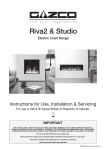
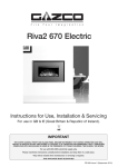
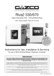
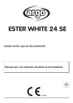
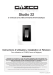
Riva2
800 & 1050 Balanced Flue
Instructions for Use,
Installation and Servicing
For use in Great Britain and Eire (GB, IE)
IMPORTANT
This product contains a Heat resistant glass panel. This panel should be checked during Installation and at each servicing
interval. If any damage is observed on the front face of the glass panel (scratches, scores, cracks or other surface defects), the
glass panel must be replaced and the appliance must not be used until a replacement is installed. Under no circumstances
should the appliance be used if any damage is observed, the glass panel is removed or broken.
Parts of this appliance will become hot during operation; it is therefore recommended that a suitable guard should be used for
protection of young children, the elderly or infirm.
This appliance is guaranteed for 2 years (subject to the conditions on page 3 of this Instruction manual). The second year of the
guarantee will only be valid if the annual service recommended in this Instruction manual has been completed by a GasSafe
registered engineer, and a copy of the service report is available for inspection by a Gazco engineer.
These Instructions must be left with the appliance for future reference and for consultation when servicing the appliance. Please
make the customer aware of the correct operation of the appliance before leaving these instructions with them.
The commissioning sheet found on Page 3 of this Instruction manual must be completed by the Installer prior to leaving the
premises.
PR1070 Issue 5 (February 2011)
COVERING THE FOLLOWING MODELS:
Riva2 800:
Riva2 1050:
134-031
134-476
134-225
134-568
PAGE
Appliance commissioning checklist
3
user instructions
4
instaLlation Instructions
13
Technical Specifications
13
Site Requirements
14
Installation
19
Commissioning
31
Servicing Instructions
32
Fault Finding
32
How to replace parts
34
Basic spare parts list
40
Service Records
41
2
APPLIANCE COMMISSIONING CHECKLIST
IMPORTaNT NOTICE
Explain the operation of the appliance to the end user, hand the completed instructions to them for safe keeping,
as the information will be required when making any guaranteed claims.
FLUE CHECK
Pass
1.
Flue is correct for appliance
2.
Flue flow test N/A
3.
Spillage test N/A
Fail
GAS CHECK
1.
Gas soundness & let by test
2.
Standing pressure test
mb
3.
Appliance working pressure (on High Setting)
mb
NB All other gas appliances must be operating on full
4.
Gas rate
5.
Does ventilation meet appliance requirements N/A
m3/h
DEALER AND INSTALLER INFORMATION
Dealer . . . . . . . . . . . . . . . . . . . . . . . . . . . . . . . . . . . . . . . . . . . . . . . . . . . . . . . . . . . . . . . . . . . . . Installation Company . . . . . . . . . . . . . . . . . . . . . . . . . . . . . . . . . . . . . . . . . . . . . . . . .
. . . . . . . . . . . . . . . . . . . . . . . . . . . . . . . . . . . . . . . . . . . . . . . . . . . . . . . . . . . . . . . . . . . . . . . . . . . . . . . ................................................................................
. . . . . . . . . . . . . . . . . . . . . . . . . . . . . . . . . . . . . . . . . . . . . . . . . . . . . . . . . . . . . . . . . . . . . . . . . . . . . . . ................................................................................
Contact No.. . . . . . . . . . . . . . . . . . . . . . . . . . . . . . . . . . . . . . . . . . . . . . . . . . . . . . . . . . . . . . Engineer . . . . . . . . . . . . . . . . . . . . . . . . . . . . . . . . . . . . . . . . . . . . . . . . . . . . . . . . . . . . . . . . . . . Date of Purchase. . . . . . . . . . . . . . . . . . . . . . . . . . . . . . . . . . . . . . . . . . . . . . . . . . . . . . . Contact No.. . . . . . . . . . . . . . . . . . . . . . . . . . . . . . . . . . . . . . . . . . . . . . . . . . . . . . . . . . . . . . . Model No.. . . . . . . . . . . . . . . . . . . . . . . . . . . . . . . . . . . . . . . . . . . . . . . . . . . . . . . . . . . . . . . . Gas Safe Reg No. . . . . . . . . . . . . . . . . . . . . . . . . . . . . . . . . . . . . . . . . . . . . . . . . . . . . . . . Serial No.. . . . . . . . . . . . . . . . . . . . . . . . . . . . . . . . . . . . . . . . . . . . . . . . . . . . . . . . . . . . . . . . . Date of Installation . . . . . . . . . . . . . . . . . . . . . . . . . . . . . . . . . . . . . . . . . . . . . . . . . . . . Gas Type. . . . . . . . . . . . . . . . . . . . . . . . . . . . . . . . . . . . . . . . . . . . . . . . . . . . . . . . . . . . . . . . . . This product is guaranteed for 2 years from the date of installation, as set out in the terms and conditions of sale between Gazco and your
local Gazco dealer. This guarantee will be invalid, to the extent permitted by law, if the above Appliance Commissioning Checklist is not
fully completed by the installer and available for inspection by a Gazco engineer. The guarantee will only be valid during the second
year, to the extent permitted by law, if the annual service recommended in the Instructions for Use has been completed by a Gas Safe
registered engineer, and a copy of the service visit report is available for inspection by a Gazco engineer.
3
USER INSTRUCTIONS
1. general
In the event of a gas escape or if you can smell gas,
please take the following steps:
•
•
•
•
•
•
1.8
Do not use a garden sprinkler or hose near the terminal.
1.9
This product is guaranteed for 2 years from the date of
installation, as set out in the terms and conditions of sale
between Gazco and your local Gazco dealer. Please consult
with your local Gazco dealer if you have any questions. In
all correspondence always quote the Model Number and
Serial Number.
Immediately turn off the gas supply at the meter/
emergency control valve
Extinguish all sources of ignition
Do not smoke
Do not operate any electrical light or power switches
(On or Off)
Ventilate the building(s) by opening doors and windows
Ensure access to the premises can be made
IMPORTANT : NEVER position an LCD/Plasma TV above this fire.
2. lighting the appliance
Please report the incident immediately to the National
Gas Emergency Service Call Centre on 0800 111 999
(England, Scotland and Wales) , 0800 002 001 (N.
Ireland) or in the case of LPG, the gas supplier whose
details can be found on the bulk storage vessel or
cylinder.
The gas supply must not be used until remedial action
has been taken to correct the defect and the installation
has been recommissioned by a competent person.
1.1
Installation and servicing must only be carried out by a
competent person whose name appears on the Gas Safe
register. To ensure the engineer is registered with Gas Safe
they should possess an ID Card carrying the following logo:
There are two ways of lighting the appliance:
• by thermostatic remote control, see 2A
• using the fire’s touch pad, see 2B
2A - THERMOSTATIC and TIMER REMOTE CONTROL
1
Up
Down
AR2302
1.2
In all correspondence, please quote the appliance type and
serial number, which can be found on the data badge
located on a plate attached to the lower slotted trim,
Diagram 5 Installation Section.
1.3
Do not place curtains above the fire:
You must have 300mm (1’) clearance between the fire and
any curtains at either side.
1.4
If any cracks appear in the glass panel do not use the
appliance until the panel has been replaced.
1.5
In the unlikely event the appliance is receiving interference
from other electronic devices, the handset/Control box can
be reprogrammed. Please consult your dealer if you think
this may be the case.
1.6
If, for any reason, the flue has to be removed from the
appliance, the seals must be replaced in the inner spigot.
1.7
Do not obstruct the flue terminal in any way, i.e. by
planting flowers, trees shrubs etc in the near vicinity, or by
leaning objects up against the terminal guard.
4
Turning the appliance On
Your remote can control the gas fire from pilot ignition
through to shut down.
To turn the fire on:
• Press the OFF button and the UP button simultaneously.
You hear several short signals.
The pilot and main burner ignite and the remote is now
in Manual Mode:
In ‘MANUAL MODE’ you can:
• turn on the main burner using the UP button
• regulate the flame from high to low and back
• turn off the burner leaving just the pilot burning
In ‘TEMP MODE’ (Automatic) you can:
• set the room temperature so the thermostat in the
remote automatically maintains that temperature
In ‘TIMER MODE’ (Automatic) the fire:
• turns on and off according to the set time periods
• automatically regulates the room temperature during the
set periods
USER INSTRUCTIONS
NOTE: When operating the fire in Temp or
Timer mode, the pilot remains lit and the fire
then automatically switches on at
programmed times to bring the room to the
set temperature whether or not you are in
the room.
NEVER LEAVE ANY COMBUSTIBLE MATERIALS WITHIN 1
METRE OF THE FRONT OF THE APPLIANCE.
2.4
TIMER MODE (AUTOMATIC)
There are two programmable settings you can make over a
24 hour period, P1 and P2. These are normally used to
provide an early morning and evening setting for each
working week:
P1 +
= Start Timed Setting 1
P1 +
= End of Timed Setting 1
P2 +
= Start Timed Setting 2
P2 +
= End of Timed Setting 2
2.4.1 P1 - Program 1 for a Timed Setting
• Press the SET button until the TIMER mode is displayed
• Hold the SET button. The displays flashes the current
time for P1. While the time displayed is flashing you can
alter the hours and minutes set.
To set the time your fire first lights, change P1
• Press the UP button to alter the hour
• Press the DOWN button to alter the minutes in 10 minute increments
• Press SET again to move to the end setting for P1 This is the time your Studio first shuts down:
• Press the UP button to alter the hour
• Press the DOWN button to alter the minutes
2.4.2 P2 - Program 2 for a Timed Setting
Use the same steps outlined in 2.4.1 to change the setting
for P2.
If you have already set P1 and want to alter the setting for
P2 only:
• Press the SET button until TIMER mode is displayed
• Hold the SET button until the display flashes the current time for P1
• Press the SET button once again to scroll past
the settings for P1 and P1
With the time s t i l l flashing:
• Press the UP button to alter the hour
• Press the DOWN button to alter the minutes
Once all four times are set press the OFF button.
2.4.3 To view existing settings:
• Select Timer Mode
• Press and briefly hold the SET button you see the start
time for P1
• Repeat the above step for the start and end of each
program.
2.1
SWITCHING BETWEEN MODES
• Press the SET button to change to Temperature Mode
• Press again to change to Timer Mode
• Keep pressing to run through all operating modes. These are:
•
MAN
•
DAY TEMP
•
NIGHT TEMP
•
TIMER and back to MAN
NOTE: MAN mode can also be reached by pressing
either the UP or DOWN button
2.2
MAN MODE
• Press the OFF button and the UP button simultaneously.
You hear several clicks and audible beeps as the fire begins
the ignition process , (up to 30 seconds)
Turning the appliance Off
• Press the OFF button to turn the appliance off
FOR SAFETY, YOU MUST WAIT 30 SECONDS BEFORE
LIGHTING THE FIRE AGAIN.
INCREASE FLAME HEIGHT
• Press the UP button once to increase flame height one
stage. Press and hold the UP button to increase to
maximum.
DECREASE FLAME HEIGHT
• Press the DOWN button once to decrease flame height one stage. Press and hold the DOWN button to decrease to
minimum. At the lowest point the fire goes to 'Standby
Mode' (Only Pilot lit).
2.3
NOTE: If you would like the Night temperature control
to turn off then decrease the temperature until [--] is
displayed.
NOTE: While pressing a button a symbol indicating
transmission appears on the display. The receiver
confirms transmission with a sound signal.
TEMP MODE (AUTOMATIC)
The display shows the current room temperature.
To increase or decrease the fire’s output:
• Press the SET button to select either the DAY TEMP or the NIGHT TEMP mode by briefly pressing the SET button
• Hold the SET button until the TEMP display flashes and then let go
• Set the desired temperature with the UP and DOWN arrows. (Minimum temperature 5C, maximum 40C or 40F to 99F when fahrenheit is the preferred option)
• Press the OFF button to stop the display flashing or wait
to return to TEMP mode.
NOTE: If you set a temperature that is beneath the
current room temperature, the fire automatically
switches to PILOT (Stand by).
2.5 LOW BATTERY
“BATT” is displayed on the remote when its batteries need
replacement.
2.6
5
SETTING THE TIME
• Simultaneously press the up and down buttons
• Press the up button to set the hour and the down button to set the minutes
• Press OFF to return to the manual mode or simply wait
USER INSTRUCTIONS
2.7
SETTING THE °C/24 HOUR OR °F/12 HOUR CLOCK
• Press OFF and the down arrow until the display changes from °C/24 hour clock to °F/12 hour clock and vice versa.
If the remote is removed, lost or damaged, signals
transmitted to the receiver cease. Your fire will go to
standby (pilot) mode after 6 hours.
3. CLEANING the RIVA2
2B - TOUCH PAD CONTROL
2
3.1
Make sure the fire and surrounds are cool before cleaning.
Use a damp cloth to clean the painted frame and use soap
and water for the glass.
Clean the burner using a vacuum cleaner with a soft brush
attachment. Ensure all debris is removed from the burner
ports.
In the unlikely event soot is deposited on the logs, use a soft
brush to remove.
3.2
To remove the glass door:
Remove the side trims, Diagram 4
4
AR1885
The UP button to increase the flame height. Press the
DOWN button to decrease the flame height. At the lowest
point it goes to ‘standby mode’, (only pilot lit). Press the ON-OFF button again to turn the appliance off
2C EMERGENCY SHUT OFF
If the batteries fail during use of the fire, move the switch to
the OFF (O) position, Diagram 3
(This switch is set to be ON during normal operation and
must remain ON)
AR2280
To operate the switch insert a thin screwdriver through the
semi circular cut out in the lower slotted trim. The switch is
located on the right hand side of the appliance under the
slotted trim.
These are held on by magnets.
3.3
Lift out the bottom slotted trim, Diagram 5
5
TAKE EXTREME CARE AS THE GLASS WILL BE VERY HOT
3
AR2279
AR2273
3.4
6
Remove all the screws around the door.
(10 on the 800 model and 9 on the 1050 model)
Please note: The screws are located down both sides and
along the bottom edge of the glass frame.
USER INSTRUCTIONS
3.5
Lift the door using the handle, up and over the lower edge
Take extreme care not to damage the paint, Diagram 6
8
6
AR2305
PLEASE ENSURE NO WIRES ARE TRAPPED BEFORE
REPLACING THE WALL PLATE. THE TOUCH PAD LEAD
IS EASILY DAMAGED
5. ARRANGEMENT OF FUEL BED
AR2275
3.6
Lower the door - the top edge will be hooked onto the top
of the appliance.
3.7
Hold the sides of the door and lift approximately 25mm
and pull the top forward. This will release the door - Lower
to clear the appliance
3.8
Refit in reverse order. When refitting the door ensure the
top is hooked over the lip on the firebox, Diagram 6.
ADVICE ON HANDLING AND DISPOSAL OF FIRE CERAMICS
4. CHANGING THE appliance BATTERIES
The appliance batteries are located behind the wall switch
plate.
4.1
Undo the two screws securing the wall switch and plate and remove, Diagram 7
The fuel effect in this appliance is made from Refractory
Ceramic Fibre (RCF), a material which is commonly used for
this application.
7
AR2304
4.2
Unclip the battery holder from the wall switch and remove
the old batteries.
4.3
Correctly position the four new AA size batteries into the
battery holder. Re-assemble the battery holder as shown in
Diagram 8
When servicing the appliance it is recommended that the
replaced items are not broken up, but are sealed within
heavy duty polythene bags and labelled as RCF waste.
RCF waste is classed as stable, non-reactive hazardous waste
and may be disposed of at a licensed landfill site.
Excessive exposure to these materials may cause temporary
irritation to eyes, skin and respiratory tract; wash hands
thoroughly after handling the material.
5.1
Vermiculite for Logs Layout
Use the entire bag of supplied Vermiculite.
TAKE CARE NOT TO SPILL VERMICULITE INTO THE
PILOT AREA. ONLY VERMICULITE SUPPLIED BY GAZCO
SHOULD BE USED IN THIS FIRE.
5.2
Log Layout
LOGS MUST BE POSITIONED ACCORDING TO
THE FOLLOWING INSTRUCTIONS TO GIVE THE
CORRECT FLAME EFFECT
5.3
Use all the vermiculite to fill the burner tray and spread
evenly across the whole burner
The centre ramp does not have vermiculite on it.
7
Protective clothing is not required when handling these
articles, but we recommend you follow normal hygiene
rules of not smoking, eating or drinking in the work area
and always wash your hands before eating or drinking.
To ensure that the release of RCF fibres are kept to a
minimum, during installation and servicing a HEPA filtered
vacuum is recommended to remove any dust accumulated
in and around the appliance before and after working on it.
USER INSTRUCTIONS
The logs are identified with letters A - H on the underside
or rear of the log. A, B, C, D and G have holes to locate the
logs on the pins fixed to the burner skin, Diagram 9.
There are two bags of effect material. One consists of black
embers, the other is a special pack of Embaglow. This looks
like wire wool and is placed after the logs are arranged.
Logs E and F have interlocking recesses which locate with
logs B and D. H has no locations but will rest in a specific
position.
5.4
Locate Log A on the pin in front of the pilot. Ensure the left
hand side of the log rest on the upper part of the burner,
Diagram 9
9
G
B
A
A
D
5.5
C
Locate Log B on the top left hand pin. The end of the log nearest the front of the appliance will rest on the side liner on the 800
model. On the 1050 model a distance of 25-30mm between the front left corner of the burner and the log is required, Diagram 10
10
B
A
5.6
Locate Log C on the lower burner right hand pin. The rear of the log should touch the black air guide between the upper and lower
burners, Diagram 11
11
C
B
A
8
USER INSTRUCTIONS
5.7
Locate Log D on the lower left hand pin. The hole is in the short branch of the log. The left hand side of the log sits in the groove on
Log B, Diagram 12
12
B
C
D
A
5.8
Place Log E on top of Log D. Engage the raised location into the recess on Log E. The rear of the log pushes against the right side of
the raised tag on the rear of the burner, see Diagram 13
13
B
E
C
D
A
5.9
Place Log F on top of Log B and engage the raised locator into the recess on Log F. The right end of the log pushes against the raised
tag on the rear of the burner, Diagram 14
14
F
B
E
C
D
A
9
USER INSTRUCTIONS
5.10 Place Log G on the two remaining pins. The charred effect faces forward, Diagram 15
15
F
B
G
E
C
D
A
5.11 Log H locates on three points. The short branch locates in the recess on the Left Hand side of Log G. The main body of Log H rests on
Log E and the front charred area of Log H rests between Log A and C on the raised tag, Diagram 16
16
H
F
G
B
C
D
A
5.12 The black embers are now placed underneath the logs C and D on the lower burner only.
A few embers are placed between Logs D and A. Place the remaining embers between logs A and C.
For best effect ensure no black embers are forward of the log front faces, Diagram 17
17
H
F
G
B
C
D
A
10
USER INSTRUCTIONS
5.13 Lastly locate the Embaglow wire wool. Take care when positioning to ensure the best final effect.
Note: ONLY half the material supplied is used
Separate half the material by hand and place the remainder back in the bag - the customer must keep this for use in the future.
The material must be pulled into shape until only a very thin layer is applied onto the burner - too much material being used can
diminish the flame effect.
The size of each piece is approximate. Loose strands of material can be trimmed with a pair of scissors. This will make it easier to
apply.
There are six areas the Embaglow is placed in. Ensure it does not overhang the front of the burner, Diagram 18 and 19
18
100
70
70
30
30
100
30
100
80
30
30
30
AR2247
19
AR2247
NOTE: This material will last approximately 500 hours burning. It is a consumable part and should be replaced when necessary. It can
be purchased from your local dealer, Part No. GZ8471.
9. servicing
7. flame failure device
7.1
9.1
This is a safety feature incorporated on this appliance which
automatically switches off the gas supply if the pilot goes
out and fails to heat the thermocouple.
8. running in
8.1
The surface coating on the materials used in your GAZCO
fire will "burn off" during the first few hours of use
producing a harmless and temporary odour. This will
disappear after a short period of use. If the odour persists,
ask your installer for advice.
The fire must be serviced every 12 months by a qualified
Gas Engineer. In all correspondence always quote the
Model number and the Serial number which may be found
on the data badge which is attached to the lower slotted
trim.
10. ventilation
10.1 Any purpose provided ventilation should be checked
periodically to ensure that it is free from obstruction.
11
USER INSTRUCTIONS
11. installation details
11.1 Your installer should have completed the commissioning
sheet at the front of this book. This records the essential
installation details of the appliance. In all correspondence
always quote the Model number and Serial number.
12. HOT SURFACES
12.1 Parts of this appliance become hot during normal use.
• Regard all parts of the appliance as a ‘working surface’
• Provide a suitable fire guard to protect young children and the infirm
13. FIRE WILL NOT LIGHT
13.1 If you cannot light the Riva2:
• Check that the emergency shut off switch is in the ON (1) position, see Section 2C, Emergency Shut Off
• Check and change the batteries in the remote handset
• Check and change the appliance batteries, Section 4
• Consult your Gazco dealer if the Riva2 still does not light
12
INSTALLATION INSTRUCTIONS
TECHNICAL SPECIFICATION
COVERING THE FOLLOWING MODELS:
Model
Gas
CAT.
Gas Type
riva2 800
riva2 1050
134-031
134-225
134-476
134-568
Working
Pressure
Aeration
Injector
Gas Rate
m3/h
Input kW
(Gross)
High
Low
Country
Riva2 800 BF
I2H
Natural (G20)
20mbar
12mm Ø
600
0.835
9.0
4.5
GB, IE
Riva2 800 BF
I3P
Propane (G31)
37mbar
14.5mm Ø (x2)
150
0.316
8.4
4.2
GB, IE
Riva2 1050 BF
I2H
Natural (G20)
20mbar
12mm Ø
600
0.835
9.0
4.5
GB, IE
Riva2 1050 BF
I3P
Propane (G31)
37 mbar
14.5mm Ø (x2)
150
0.316
8.4
4.2
GB, IE
Efficiency Class 2 - 82% / NOx Class 5
Flue Outlet Size Ø 150mm
Flue Inlet Size Ø 100mm
Gas Inlet Connection Size Ø 8mm
RESTRICTOR REQUIREMENT
VERTICAL & HORIZONTAL FLUE
TOP EXIT - VERTICAL ONLY INCLUDING OFFSET
RIVA2 800 BF
RIVA2 BF 800 and 1050
Vertical Flue Height
Horizontal Length
Restrictor Size
Vertical Flue Height
Restrictor Size
200mm - 500mm
Up to 500mm
No restrictor
3000 - 4990mm
60mm Ø
500mm - 1000mm
Up to 1000mm
No restrictor
5000mm - 10,000mm
52mm Ø
1000mm - 1490mm
Up to 1000mm
No restrictor
1500mm - 1990mm
Up to 5000mm
No restrictor
2000mm - 3000mm
Up to 5000mm
75mm Ø
RIVA2 1050 BF
Vertical Flue Height
Horizontal Length
Restrictor Size
200mm - 500mm
Up to 500mm
No restrictor
500mm - 1000mm
Up to 1000mm
No restrictor
1000mm - 1490mm
Up to 1000mm
No restrictor
1500mm - 1990mm
Up to 5000mm
No restrictor
2000mm - 3000mm
Up to 5000mm
75mm Ø
13
INSTALLATION INSTRUCTIONS
TECHNICAL SPECIFICATION
This appliance has been certified for use in countries other than
those stated. To install this appliance in these countries, it is
essential to obtain the translated instructions and in some cases
the appliance will require modification. Contact Gazco for further
information.
PACKING CHECKLIST
Qty Description
Fixing Kit containing:-
1 Log Set including Ember Pack
1 Vermiculite Pack
1 Chimney Renovation Kit Front Cover (Left Hand)
1 Chimney Renovation Kit Front
Cover (Right Hand)
2 Chimney Renovation Kit Rear
Cover
8 Fixing Screws (for Chimney
Renovation Kit Cover Plates)
1
1
4
1
1
2
1
1
1
x
x
x
x
x
x
x
x
x
Instruction Manual
Handset
AA cell batteries
9V cell batteries
wall box
wall plate screws
touch pad/wall plate
battery holder
Embaglow pack
AR2242
AR2243
14
INSTALLATION INSTRUCTIONS
SITE REQUIREMENTS
1.5
Two types of flue terminals are available, horizontal and
vertical. To measure for a horizontal terminal:
• Decide on the terminal position
• Measure the height from the top of the appliance to the
centre of the required outlet.
For minimum and maximum flue dimensions see Diagram 2
and 3.
• Allow enough room either above or to the side of the
appliance to assemble the flue on top
• Assemble a horizontal flue in the following order:
- Vertical section
- 90° elbow
- Horizontal plus terminal
1. Flue and Chimney Requirements
Note: This appliance must only be installed with the flue
supplied.
You must adhere to the following:
1.1 The flue must be sited in accordance with BS5440: Part 1
(latest edition). See Diagram 1.
1.2 Fit a guard to protect people from any terminal less than 2
metres above any access such as level ground, a balcony or
above a flat roof.
1.3 All vertical and horizontal flues must be securely fixed and
fire precautions followed in accordance with local and
national codes of practice.
1.4 A restrictor may be required. Refer to Technical
Specifications on page 12.
1
UK Dimensions
15
• Support the opening of a masonry installation with a lintel.
1.6
Only the horizontal terminal section can be reduced in size.
INSTALLATION INSTRUCTIONS
SITE REQUIREMENTS
RIVA2 1050 - Kit No. 8523
2. FLUE OPTIONS
RIVA2 800 BF
Vertical from the top of the appliance then horizontally
out. (See Diagram 3). The basic kit comprises:
1 x 500mm vertical length
1 x 500mm terminal length (cut to length on site)
1 x 90° elbow
1 x wall plate
1 x 75mm restrictor
2
The kit may be used on its own. (Note – RIVA2 800 with a
200mm rise only the 500mm terminal length can be used).
Extra lengths may be added to the vertical and horizontal
from the list below, See Section 2.5
2.2 TOP FLUE UP & OUT WITH ADDITIONAL
BEND
Any additional bend may be used on the horizontal section
(either 45° or 90°), but the overall horizontal flue run will
be reduced. Refer to Diagram 4.
AR1671
4
RIVA2 1050 BF
3
AR2246
Riva2 800 & 1050
When A = 1.0 to 1.499 metres B + C = 1.0 metres maximum
When A = 1.499 metres to 3.0 metres B + C = 4.0 metres maximum
Start of bend to centre line of horizontal flue 170mm.
Centre line of vertical flue to end of bend 220mm.
2.1 TOP FLUE UP & OUT KIT
AR1672
RIVA 2 800 - Kit No. 8534
2.3 TOP FLUE VERTICAL KIT (8524/8524AN)
Vertical from the top of the appliance then horizontally out.
(See Diagram 2). The basic kit comprises:
1 x 200mm vertical length
1 x 500mm terminal length (cut to length on site)
1 x 90° elbow
1 x wall plate
1 x 75mm restrictor
1 x 70mm restrictor - Not used on this appliance
1 x 60mm restrictor - Not used on this appliance
16
Vertical from the top of the appliance (See Diagram 5).
A minimum vertical rise 3m (9’10") to a maximum 10m
(32’10"). The basic kit comprises:
2 x 1m lengths
1 x 1m terminal length
1 x 52mm restrictor
1 x 47mm restrictor - Not used on this appliance
1 x 60mm restrictor
1 x 70mm restrictor - Not used on this appliance
Extra lengths may be added from the list below.
INSTALLATION INSTRUCTIONS
SITE REQUIREMENTS
5
3. GAS SUPPLY
AR1673
This appliance is intended for use on a gas
installation with a governed meter.
3.1
Before installation, ensure that the local distribution
conditions (identification of the type of gas and pressure)
and the adjustment of the appliance are compatible.
3.2
Ensure the gas supply delivers the required amount of gas
and is in accordance with the rules in force.
3.3
You can use soft copper tubing on the installation and soft
soldered joints outside the appliance and below the fire.
3.4
A factory fitted isolation device is part of the inlet
connection; no further isolation device is required.
3.5
All supply gas pipes must be purged of any debris that may
have entered prior to connection to the appliance.
3.6
The gas supply enters through the aperture located on the
RIGHT-HAND side of the box.
2.4 TOP FLUE VERTICAL OFFSET KIT
(8530/8530AN)
4. VENTILATION
Used with kit 8524. A minimum rise of 500mm (191/2) is
required to the first bend. See Diagram 5.
4.1
2.5 EXTRA FLUE LENGTHS
5. APPLIANCE LOCATION
All flue components are 150mm diameter (6")
NOMINAL
LENGTH
Actual
LENGTH
Stainless
finish
Anthracite
finish
200mm
140mm
8527
8527AN
500mm
440mm
8528
8528AN
1000mm
940mm
8529
8529AN
40° Bend
N/A
8507
8507AN
90° Bend
N/A
8508
8508AN
RIVA 2 BALANCED FLUE INSTALLATION FOR
STUDWORK/FALSE CHIMNEY BREAST.
5.1
While the figures quoted in these instructions for clearances
to combustible materials etc conform to the relevant
standards; it is advisable to read the following notes.
5.2
Due to the high efficiency and high temperatures expected
from a Glass Fronted Appliance it is advisable to plan
carefully the exact method of installation.
It is generally considered that the temperatures are higher
on a balanced flue version due to the extra efficiency.
NOTE: Carefully consider:
a)
Terminal positions
b)
Flue supports
c)
Weatherproofing
d)
Fire precautions
5.3
For all the above options, you must conform to local and
national codes of practice.
2.6 CHIMNEY RENOVATION KIT (999-668)
This appliance requires no additional ventilation.
5.4
Details of the Chimney Renovation Kit are available in the
separate Installation Instructions - PR1181 Chimney
Renovation Kit Instructions.
17
The studwork can be formed using metal or wood
framework paying particular attention to the diagram
showing combustible material distances.
The carcass must consist in part of totally fire proof materials
such as Supalux, Masterboard or Monolux.
The fireproof board names as shown above are factory
names and so there will be others available. (Contact your
local building supplier)
It is strongly recommended that a single sheet of this
material also surrounds the fascia of the appliance to the
sides and to the top to provide maximum heat proofing.
Plasterboard can be used on the outer limits of your false
chimney breast/studwork and then it should be possible to
PVA the construction using a neat solution and a plaster
finish.
INSTALLATION INSTRUCTIONS
SITE REQUIREMENTS
5.5
There are also Plaster products on the market which can be
used in areas of higher temperatures that have successfully
been used in some installations. (Vitcas and Envirograf are
two examples)
It may be prudent to contact the suppliers or manufacturers
of these products to check your particular application or
requirements.
5.6
Please remember that the expansion and contraction
properties will be different between fireproof boarding and
plasterboard and so a joint, or introduction of the two
materials too close to the appliance may result in plaster
cracking.
5.7
To avoid an unnecessary build up of heat in the void
created, fit 2 vents at high level.
The high level vents could be fitted at such a height that
following engineers on a service could in fact inspect any
flue work in the void.
The enclosure must also be constructed to leave a gap
between the top of the wall and the ceiling.
IMPORTANT : NEVER position an LCD/Plasma TV above this fire.
5.10
5.11 This appliance must stand on a non-combustible platform
that is at least 12mm thick.
5.12 Although a hearth is not required, consideration for the
young, elderly and infirm should be given. This is to prevent
accidental touching of the glass as it reaches high
temperature.
5.8
Please note this appliance has been primarily designed for
studwork applications. However, there are circumstances
where the appliance could be installed in a block or
brickwork fireplace using different methods and materials
for the final effect. This void must be vented, See Diagram
4, Section 2.
5.9
This appliance is not suitable for installation onto a
combustible wall. Remove all combustible material from the
area shown. See Diagram 6
6
150
100
AR2250
A combustible shelf must be:
• maximum 150mm in depth
• minimum, 150mm high above the fire
A combustible side wall must be a minimum of 150mm
from the appliance.
NOTE: If you intend to construct the fascia of the
fireplace opening from natural materials it is
recommended you cut this into three or more sections to
prevent cracking. Resin-based materials may not be
suitable. This appliance is an effective heat producer and
attention must be paid to the construction and finish of
the fireplace.
18
INSTALLATION INSTRUCTIONS
INSTALLATION
IMPORTANT NOTE: DUE TO THE DESIGN OF THE
APPLIANCE NO CONVECTED AIR IS EMITTED FROM
THE FRONT. WHEN INSTALLED IN THE FALSE CHIMNEY
BREAST ALL THE HOT AIR IN THE VOID IS RETURNED
INTO THE ROOM THROUGH EITHER THE TWO VENTS
OR THE GAP LEFT AT THE TOP OF THE WALL.
1
Skimmed Finish
IMPORTANT: REFER TO DATA BADGE AND TECHNICAL
SPECIFICATION AT THE FRONT OF THE MANUAL TO
ENSURE THE APPLIANCE IS CORRECTLY ADJUSTED FOR
THE GAS TYPE AND CATEGORY APPLICABLE IN THE
COUNTRY OF USE. FOR DETAILS OF CHANGING BETWEEN GAS TYPES
REFER TO SECTION 14, SERVICING, ‘REPLACING PARTS’.
Wall Finish
1. SAFETY PRECAUTIONS
1.1
For your own and other’s safety, you must install this
appliance according to local and national codes of practice.
Failure to install the appliance correctly could lead to
prosecution. Read these instructions before installing and
using this appliance.
1.2
These instructions must be left intact with the user.
1.3
Do not attempt to burn rubbish on this appliance.
1.4
Keep all plastic bags away from young children.
1.5
Do not place any object on or near to the appliance and
allow adequate clearance above the appliance.
IF THE APPLIANCE IS EXTINGUISHED OR GOES OUT IN
USE, WAIT 3 MINUTES BEFORE ATTEMPTING TO
RELIGHT THE APPLIANCE.
AR2254
IF IT IS INTENDED TO FIT THIS APPLIANCE WITH A
GAZCO STONE FIREPLACE, MANTEL OR HEARTH & SLIP
SET, IT WILL BE NECESSARY TO REFER TO THE
INSTRUCTIONS SUPPLIED WITH THE SURROUND OR
MANTEL TO ENSURE THE RIVA2 IS INSTALLED AT THE
CORRECT HEIGHT, See Diagram 1A
1A
2. INSTALLATION METHODS
THE appliance can be installed into a false chimney
breast. This is constructed of wood or metal
studwork with a plasterboard and skimmed finish.
A brick and block construction with plasterboard
and skimmed finished can also be used.
AR2201
The final appearance of the installation falls into
one of the following categories:
1) A plastered and painted wall
2)
A stone fireplace
3)
A tiled or marble finish
For installation 3 if the tile or marble is to
finish flush with the black frame then the
wall finish will have to be a set distance
behind the frame depending on the tile/marble thickness, see diagram 2
a fixing kit is available for this installation:
800 KIT NO: 999-440
1050 KIT NO: 999-321
The appliance has a purpose built frame to ensure
the wall finish is always in the correct position.
For installations 1 and 2 the wall finish sits
against the flanges on the sides and the vertical
faces top and bottom of the black frame, see
diagram 1
19
Attach the upper bar by screwing through
the top of the black frame using the screw
provided. This forms a vertical face to
support the tile/marble finish, Diagram 2.
The lower bar is attached under the bottom
of the black frame. The screws are inserted
INSTALLATION INSTRUCTIONS
INSTALLATION
downwards behind the frame, Diagram 2.
Due to the expansion of metal it is advisable
not to use adhesive between the tile/marble and the support bars.
Only use adhesive between the tile/marble and the wall finish.
3
2
Fixing screw
Tile/Marble
Upper Bar
AR2248
2.2
DO NOT PACK THE VOID AROUND OR ABOVE THE
APPLIANCE WITH INSULATION MATERIALS SUCH AS
MINERAL WOOL.
2.3
THE VOID BUILT FOR THE CASSETTE MUST BE
VENTILATED TO PREVENT A BUILD-UP OF HEAT. YOU
MUST FIT 2 VENTS OF APPROXIMATELY 100CM2 EACH.
THESE VENTS RETURN WARM AIR BACK INTO THE
ROOM, SEE DIAGRAM 4
Tile/Marble
4
Lower Bar
Fixing screw
AR2253
Alternatively the tile/marble can overhang forward of the black frame but must not
protrude inside so as to reduce the size of
the door frame aperture.
2.1
DISTANCE TO COMBUSTIBLE MATERIAL
COMBUSTIBLE PARTS OF THE STUDWORK MUST BE
KEPT BEYOND THE MINIMUM DIMENSIONS SHOWN
IN DIAGRAM 3. EVEN IF THE FRAMEWORK IS
PROTECTED BY NON-COMBUSTIBLE MATERIAL, YOU
MUST MAINTAIN THESE DIMENSIONS, DIAGRAM 3.
75mm
AR2249
20
2.4
alternatively the enclosure can be
constructed to leave a gap between the top
of the wall and the ceiling. ensure the open
area is equal to or greater than the two
vents.
2.5
AN ACCESS HATCH MUST BE LEFT IN THE SIDE OF THE
CHIMNEY BREAST FOR FUTURE SERVICING AND
INSPECTION OF THE FLUE AND APPLIANCE.
INSTALLATION INSTRUCTIONS
INSTALLATION
3.5
3. installation of the appliance
3.1
Remove the appliance from the carton and discard all
unnecessary packaging.
Ensure no components are thrown away when unpacking
3.2
If the appliance is being fitted with a Gazco Chimney
Renovation Kit, the four supplied metal cover plates MUST
be fitted to the appliance heat shield - see PR1181 Chimney
Renovation Kit instructions, Section 4 Page 8.
If the Chimney Renovation Kit is NOT being used then the
cover plates can be discarded.
THE COVER PLATES MUST NOT BE FITTED TO THE
APPLIANCE IF IT IS BEING INSTALLED WITH A
STANDARD GAZCO FLUE OPTION AS LISTED IN THIS
INSTALLATION BOOKLET (Page 16 Section 2).
3.3
Remove all the screws around the door.
(10 on the 800 model and 9 on the 1050 model)
Please note: The screws are located down both sides and
along the bottom edge of the glass frame.
3.6
Lift the door using the handle, up and over the lower edge
Take extreme care not to damage the paint, Diagram 7
7
To remove the glass door:
Remove the side trims, Diagram 5
5
AR2275
These are held on by magnets.
3.4
Lift out the bottom slotted trim, Diagram 6
Lower the door - the top edge will be hooked onto the top
of the appliance.
3.8
Hold the sides of the door and lift approximately 25mm
and pull the top forward. This will release the door - Lower
to clear the appliance
3.9
Remove the box from the appliance and store safely as it
contains the remote control and fuel effects, etc.
3.10 Remove all the vermiculite liners. The rear panels can
remain in place. See Replacing Parts, Section 4.
AR2280
3.7
3.11 Remove the Main Burner, see Replacing Parts, Section 5.
3.12 The gas supply enters the fire through the RIGHT HAND
side of the appliance along with the battery and touch pad
leads, Diagram 8
6
8
Gas Inlet
AR2264
AR2279
21
INSTALLATION INSTRUCTIONS
INSTALLATION
3.17 The 8mm compression fitting can now be attached to the
flexible pipe. The pipe may be bent to suit the fitters
pipework.
Riva 2 gas inlet pipe
The Riva 2 is supplied with a flexible pipe extension to aid
installation from the appliance inlet to the rigid gas supply pipe.
4. STUDWORK INSTALLATION FOR RIVA 2
3.13. To fit the Gas Inlet extension:
Gain access to the isolating elbow
NOTE: if the appliance is to be raised off the
floor ensure the platform is suitably
supported. these appliances are very heavy.
4.1
Build the studwork chimney breast and enclosures to the desired size to include the protected platform at the required height.
4.2
Line the aperture for the appliance with 12mm thick non- combustible material as shown, Diagram 13 and 14.
3.14 Remove the isolating elbow from the inlet pipe
3.15 Bend the flexible pipe as shown, Diagram 10.
10
13
AR2363
3.16 Fix the isolating elbow on the flexible pipe and secure using
an 8mm Pipe Nut.
11
Isolating Elbow
8mm
Pipe Nut
AR2255
Flexi-pipe
14
AR2364
3.17. Thread the flexible pipe through the top of the control
cover and out of the access hole in the side of the
appliance. Attach the isolating elbow back onto the inlet
pipe, See page 21 for details on the Isolating Elbow.
150
12
AR2256
Flexi-pipe
AR2365
22
INSTALLATION INSTRUCTIONS
INSTALLATION
• Do Not fit a timber bottom on the floor in front of the
appliance as this will block the airflow
Use the metal bracket provided, Diagram 9.
5. wall box & battery installation
• Ensure the clearances are maintained, Diagram 11
• Site the appliance and decide on flue requirements
• Cut a hole for the flue exit - see Installation
Instructions, Flue Assembly
• Provide gas into the cassette void on the right-hand side
NOTE: The touch pad and battery lead are long enough
to allow the touch pad and battery box to be sited on the
left hand side of the appliance.
4.3
Fit non-combustible board to the studwork around the fire. This should extend a minimum of 150mm above the
appliance and at least 100mm to the sides of the appliance,
Diagram 15.
It is however recommended that this is extended further to
prevent cracking.
When installing the wall box allow at least 100mm of slack
wire in the touch pad lead and battery lead where they
enter the appliance on the right hand side. This allows the
removal of the control assembly during servicing
5.1
Decide on the position for the wall box containing the
batteries and wall switch and cut the necessary hole.
Connect the wire from the fire to the battery pack, Diagram
17.
17
15
AR1920
5.2
150
Connect the wire from the fire to the touch pad/connector,
Diagram 18.
18
100
AR2250
4.4
Apply plasterboard to the remainder of the studwork.
Apply a plaster finish to the front of the chimney breast.
4.5
To finish this installation connect the wall box and batteries
following instruction in Section 5 below/
Connect:
- the flue system (see Installation, Flue Assembly)
- and gas services (see Installation 2.3) using the opening
in the side of the chimney breast for access.
AR2306
5.3
Correctly position the four new AA size batteries and
re-assemble the battery holder as shown, Diagram 19.
19
After commissioning finish the sides of the chimney breast,
Diagram 16.
12
AR2305
5.4
AR1905
23
Secure the wall switch plate to the wall box using the two
fixing screws, Diagram 20.
INSTALLATION INSTRUCTIONS
INSTALLATION
20
Drill small holes around the circumference when using
method b. Make good both ends of the hole.
6.6
Allow enough room either above or to the side of the
appliance to assemble the flue on top.
Assemble a horizontal flue in the following order:
- Vertical section
- 90° elbow
- Horizontal plus terminal
Support the opening of a masonry installation with a lintel.
6.7
Only the horizontal terminal section can be reduced in size.
wall plate
AR2304
5.5
Important
The wall switch must be installed using a nonmetallic mounting box, please ensure that the plastic dry lining box is used wherever possible. If it is intended to install the wall switch on a masonry it is possible to drill through the rear of this box and secure in position using wall plugs and screws although a small amount of finishing work will be required to cover the plastic side securing tags. Alternatively a standard 47mm deep pattress box can be used to surface mount the wall switch.
To find the length measure from the outside of the wall to
the stop on the 90°
Add 10mm to the outlet end
Measure from the edge of the slots closest to the wall and mark around the flue, Diagram 21.
21
6. FLUE ASSEMBLY
10mm
6.1
Refer to Flue Options in Site Requirements on page 15.
TAKE CARE WHEN MARKING OUT FOR THE FLUE AS IT
IS DIFFICULT TO MOVE AFTER INSTALLATION. IF A
RESTRICTOR IS REQUIRED FIT THIS BETWEEN THE
SMALL OUTLET SPIGOT AND THE AIR DUCT SEE
DIAGRAM 17. REFER TO TECHNICAL SPECIFICATIONS
FOR RESTRICTOR SIZE.
AR0629
21
A wall plate is supplied to fix the flue to the wall:
Bend the tab to 90°
Assemble the plate onto the flue but wait to secure to wall
and flue after the flue is fully assembled.
6.8
The cardboard fitment in the terminal is used to support the
flue whilst it is cut to length. ONCE CUT TO SIZE,
REMOVE THE CARDBOARD REMNANT, Diagram 22.
22
AR0627
6.2
A 152mm (6") diameter hole in the wall is required to install
the flue. This can be achieved by either:
a) Core drill
b) Hammer and chisel
AR0630
24
INSTALLATION INSTRUCTIONS
INSTALLATION
TOP EXIT - VERTICAL FLUE
If a vertical only flue system has been purchased refer to
Site Requirements, Diagram 8.
The following areas need careful consideration:
a) Terminal Positions
b) Flue Supports
c) Weatherproofing
d) Fire Precautions
For all of the above, local and national codes of practice
must be adhered to.
7.1
VERMICULITE PANELS
NOTE: RIVA2 FRONT AND REAR PANELS ARE IN TWO
PIECES.
The rear panels are already in place.
Ensure the two-piece rear panels are centralised, with the
chamfers touching and pushed together, Diagram 23.
23
TABLE A - TOP EXIT - VERTICAL ONLY,
INCLUDING OFFSET
Vertical Height from Floor
Restrictor Size
3,000mm to 4,990mm
60mm Ø
5,000mm to 10,000mm
52mm Ø
Flue temp
400˚C
6.9
7. ASSEMBLING THE APPLIANCE
AR2263
Connect a suitable pressure gauge to the test point located
on the inlet fitting
• Replace the burner
NOTE: On the Riva2 1050 the burner can be permanently
fixed. The Riva2 800 burner has to be removed after the
pressure check. This is to allow access to refit the controls
cover plate.
7.2
Place the left hand and right hand L shaped lower panels
either side of the burner, Diagram 24.
24
6.10 Turn on the gas and light the appliance. Check for leaks.
6.11 Turn the appliance to maximum and check that the supply
pressure is as stated on the data badge.
6.12 Turn off the gas and replace the test point screw
6.13 Turn the gas back on and check the test point for leaks
AR2263
7.3
Place the left and right hand front strips on the front edge of
the firebox. The rear of the vermiculite strips are angled to
match the angled stops on the firebox. Centralise the strips
and ensure all the chamfers align, Diagram 25.
25
AR2266
25
INSTALLATION INSTRUCTIONS
INSTALLATION
7.4
Place the side panels on top of the lower panels and secure
with clips.
The side panels are not handed. Ensure the grooves align
with the rear panels, Diagram 26.
26
AR2257
8. ARRANGEMENT OF FUEL BED
When servicing the appliance it is recommended that the
replaced items are not broken up, but are sealed within
heavy duty polythene bags and labelled as RCF waste.
RCF waste is classed as stable, non-reactive hazardous waste
and may be disposed of at a licensed landfill site.
Excessive exposure to these materials may cause temporary
irritation to eyes, skin and respiratory tract; wash hands
thoroughly after handling the material.
8.1
Vermiculite for Logs Layout
Use the entire bag of supplied Vermiculite.
TAKE CARE NOT TO SPILL VERMICULITE INTO THE
PILOT AREA. ONLY VERMICULITE SUPPLIED BY GAZCO
CAN BE USED IN THIS FIRE.
8.2
Log Layout
LOGS MUST BE POSITIONED ACCORDING TO
THE FOLLOWING INSTRUCTIONS TO GIVE THE
CORRECT FLAME EFFECT
8.3
Use all the vermiculite to fill the burner tray and spread
evenly across the whole burner
The centre ramp does not have vermiculite on it.
ADVICE ON HANDLING AND DISPOSAL OF FIRE CERAMICS
The fuel effect in this appliance is made from Refractory
Ceramic Fibre (RCF), a material which is commonly used for
this application.
The logs are identified with letters A - H on the underside
or rear of the log. A, B, C, D and G have holes to locate the
logs on the pins fixed to the burner skin, Diagram 24.
Protective clothing is not required when handling these
articles, but we recommend you follow normal hygiene
rules of not smoking, eating or drinking in the work area
and always wash your hands before eating or drinking.
To ensure that the release of RCF fibres are kept to a
minimum, during installation and servicing a HEPA filtered
vacuum is recommended to remove any dust accumulated
in and around the appliance before and after working on it.
Logs E and F have interlocking recesses which locate with
logs B and D. H has no locations but will rest in a specific
position.
There are two bags of effect material. One consists of black
embers, the other is a special pack of Embaglow. This looks
like wire wool and is placed after the logs are arranged.
8.4
Locate Log A on the pin in front of the pilot. Ensure the left
hand side of the log rest on the upper part of the burner,
Diagram 27.
27
G
B
A
D
8.5
A
C
Locate Log B on the top left hand pin. The end of the log nearest the front of the appliance will rest on the side liner on the 800
model. On the 1050 model a distance of 25-30mm between the front left corner of the burner and the log is required, Diagram 28.
26
INSTALLATION INSTRUCTIONS
INSTALLATION
28
B
A
8.6
Locate Log C on the lower burner right hand pin. The rear of the log should touch the black air guide between the upper and lower
burners, Diagram 29.
29
C
B
A
8.7
Locate Log D on the lower left hand pin. The hole is in the short branch of the log. The left hand side of the log sits in the groove on
Log B, Diagram 30.
30
B
C
D
A
8.8
Place Log E on top of Log D. Engage the raised location into the recess on Log E. The rear of the log pushes against the right side of
the raised tag on the rear of the burner, see Diagram 31.
27
INSTALLATION INSTRUCTIONS
INSTALLATION
31
B
E
C
D
A
8.9
Place Log F on top of Log B and engage the raised locator into the recess on Log F. The right end of the log pushes against the raised
tag on the rear of the burner, Diagram 32.
32
F
B
E
C
D
A
8.10 Place Log G on the two remaining pins. The charred effect faces forward, Diagram 33.
33
F
B
G
E
C
D
A
28
INSTALLATION INSTRUCTIONS
INSTALLATION
8.11 Log H locates on three points. The short branch locates in the recess on the Left Hand side of Log G. The main body of Log H rests on
Log E and the front charred area of Log H rests between Log A and C on the raised tag, Diagram 34.
34
H
F
G
B
C
D
A
8.12 The black embers are now placed underneath the logs C and D on the lower burner only.
A few embers are placed between Logs D and A. Place the remaining embers between logs A and C.
For best effect ensure no black embers are forward of the log front faces, Diagram 35.
35
H
F
G
B
C
D
A
8.13 Lastly locate the Embaglow wire wool. Take care when positioning to ensure the best final effect.
Note: ONLY half the material supplied is used
Separate half the material by hand and place the remainder back in the bag - the customer must keep this for use in the future.
The material must be pulled into shape until only a very thin layer is applied onto the burner - too much material being used can
diminish the flame effect.
The size of each piece is approximate. Loose strands of material can be trimmed with a pair of scissors. This will make it easier to
apply.
There are six areas the Embaglow is placed in. Ensure it does not overhang the front of the burner, Diagram 36 and 37.
29
INSTALLATION INSTRUCTIONS
INSTALLATION
36
100
70
70
30
30
30
100
100
80
30
30
30
AR2247
37
AR2247
NOTE: This material will last approximately 500 hours burning. It is a consumable part and should be replaced when necessary. It can
be purchased from your local dealer, Part No. GZ8471.
10.2 Using the handle in the bottom of the frame lift the frame
over the bottom trim and locate onto the lower brackets.
Keep pressure on the top of the frame to ensure it hooks
back onto the firebox.
10. COMPLETION OF ASSEMBLY
10.1 To fit the window frame:
NOTE: IT IS ADVISABLE TO PROTECT THE LOWER
BLACK TRIM AS THIS IS EASILY SCRATCHED
10.3 Align all the holes and locate all the screws.
DO NOT TIGHTEN.
Starting with the bottom screws and working upwards
tighten all the screws in the frame.
DO NOT OVERTIGHTEN THE SCREWS.
Insert the top of the window frame behind the black trim
and hook the frame onto the vertical face of the firebox,
Diagram 38.
Carefully rest the bottom of the frame up against the
appliance
10.4 Place the slotted trim over the studs to cover the gap at the
bottom of the window. The louvres point forwards, Diagram
39
38
39
AR2279
AR2274
30
INSTALLATION INSTRUCTIONS
INSTALLATION/COMMISSIONING
10.5 Place the magnetic side trims against the sides of the black
frame, Diagram 40.
TOUCH PAD CONTROL
39
40
AR1885
AR2280
11. LIGHTING THE STUDIO
Note: The Emergency Shut Off switch must be in the ON
position, refer to Section 2, User Instructions.
There are two ways of lighting the Studio:
• by thermostatic remote control
• using the fire’s touch pad
• Press the ON-OFF button to light the appliance, (up to 30 seconds)
• Press the UP button to increase the flame height.
• Press the DOWN button to decrease the flame height. At the lowest point it goes to ‘standby mode’, (only pilot lit)
• Press the ON-OFF button to turn the appliance off.
1. COMMISSIONING
1.1
THERMOSTATIC REMOTE CONTROL
38
1.2
Complete the Commissioning Checklist at the front of this
manual covering:
• Flue checks
• Gas checks
• Log layout - flame picture
For working pressure test, use the access panel at the gas
connection ensuring the burner is in position.
In the unlikely event that the appliance is receiving
interference from other electronic devices, re-programme
the handset/Control box
Reprogramming handset/Control box
AR2304
This remote controls the appliance from pilot ignition
through to shut down. In ‘MANUAL MODE’ you can:
• light the pilot
• turn on the main burner
• regulate the flame from low to high and back
• turn off the burner leaving just the pilot burning
In ‘TEMP MODE’ you can:
• set the room temperature so the stove automatically
maintains that temperature
In ‘TIMER MODE’ the fire:
• turns on and off according to the set time periods
• automatically regulates the room temperature during the
set periods
31
To access the control box see Servicing Instructions, Section
6 - Main Control Assembly.
• Press and hold the reset button on the control box until
you hear two signals. After the second longer signal:
• Release the reset button and within 20 seconds
• Press the DOWN button on the handset until you hear an additional long signal confirming the new code
SERVICING INSTRUCTIONS
SERVICING / FAULT FINDING CHARTS
1. SERVICING REQUIREMENTS
2. Fault Finding
IMPORTANT – The glass panel on this appliance should be
checked for any signs of damage on the front face of the glass
panel (scratches, scores, cracks or other surface defects). If
damage is observed, the glass panel must be replaced and the
appliance must not be used until a replacement is installed.
Under no circumstances should the appliance be used if any
damage is observed. Please isolate the appliance until a
replacement glass panel has been obtained and installed.
Replacement glass panels can be purchased from Gazco via the
dealer from which the appliance was purchased or any other
Gazco distributor.
This appliance must be serviced at least once a year by a
competent person.
All tests must be carried out in accordance with the current Gas
Safe recommendations.
1.1 Before any tests are undertaken on the appliance:
• Conduct a gas soundness test for the property to ensure there are no gas leaks prior to starting work
1.2
• Fully check the operation of the appliance
Special checks
1.2.1 Clean any lint or fluff from the pilot - pay particular attention to the aeration holes of the pilot
1.2.2 Clean away any fluff or lint from under the burner
1.2.3 Check the spark gap on the pilot is correct
• Correct any faults found during the initial tests
• Recommission the appliance conducting the usual safety
checks
1.3 Advise the customer of any remedial action taken.
REPLACE BATTERIES BEFORE ATTEMPTING TO RECTIFY ANY
FAULTS.
IF THE FIRE DOES NOT WORK, BUT HAS WORKED IN THE
PAST: •
CHECK THE EMERGENCY SHUT OFF SWITCH IN THE BOTTOM RIGHT CORNER BY THE DOOR IS SWITCHED ON, SEE USER SECTION, PAGE 6
Electronic Control Valve Fault Analysis
Cause
Remedy
3 Short beeps from
control
Batteries low in
appliance
Replace appliance
batteries
No ignition, 5 second
continuous tone (there
may be several short
beeps before)
1. On/Off switch is in
OFF position
2. Loose/damaged
wire
1. Move switch to
ON position
2 Check interrupter
block and wires
No ignition, no tone,
motor turns slightly when
operated
Receiver board
damaged
Replace receiver
No pilot flame and
control continues to
spark
Thermocouple circuit
wired incorrectly
Correct wiring
Pilot lights, control
continues to spark, value
shuts down after 10 - 30
seconds
1. No spark at pilot
burner
2. Loose/damaged
wire
1. Rectify spark at
pilot burner
2. Check interrupter
and wires
32
SYSTEM OK
GO TO THE NEXT
CHART IGNITION
FUNCTIONAL CHECK 2
No
There is a blockage in the system, check the inlet test point,
the mag seating and valve. Check thermocouple leads for correct
orientation, condition and connection
Has the system got
any air in it?
Yes
Purge the gas pipes and
retry.
Yes
Yes
Is the gas pressure
correct?
No
Correct and
retry.
Check isolation tap and
gas meter, retry.
No
Is the gas turned on to
the appliance?
No
Will the pilot light
with a match?
Yes
Check alignment of pilot
burner head, change the
ignition lead.
See Replacing Parts, section
2.
Yes
Is the control being
operated correctly?
No
Consult User
Instructions and retry.
No
Does the pilot light?
Yes
Operate the valve.
Is there a spark?
No
Ensure there is no debris around the pilot assembly,
(e.g. soot, etc.) which could short the spark, clean the
area.
PILOT WILL NOT LIGHT
IGNITION FUNCTIONAL CHECK 1
Yes
Symptom
33
Replace the lead, retry.
No
Has the ignition lead
become detached from the
control box?
No
Replace the electrode
Yes
Correct and retry.
Check the tab on the pilot
burner is not damaged. Either
repair tab or replace pilot
burner and retry.
Is the valve being
operated correctly?
Check handset batteries are OK.
Replace if required. Check handset is
on manual. Check if handset lock is
off. Check batteries to the control
unit. Replace if required. Retry with
handset and touch pad. Check that
the on/off switch is in On position,
diagram 13 Users Instructions.
Replace the ignition
lead and retry.
Yes
Yes
No
No
Remove the ignition lead
from electrode. With insulated
pliers. Hold the tip 4.0mm from the
pilot pipe work, is there a spark
when the system is operated?
No
Has ignition lead
become detached or is
connection poor?
Yes
Is the gap between
electrode and
thermocouple 4.0mm?
Yes
From Ignition Fault
Finding Chart 1
Consult the users
instructions, retry. Ensure there is no debris around the pilot assembly,
(e.g. soot etc.) which could short the spark, clean the area.
NO SPARK
IGNITION FUNCTIONAL CHECK 2
Yes
Change the
pilot unit.
No
Is the pilot flame of the
correct length? Is the
thermocouple in its
correct position in the
pilot bracket. See
Replacing Parts, section
8.5
Yes
With the pilot
running is the gas
pressure as stated on
the data badge?
Yes
No
Will pilot
stay alight?
SYSTEM OK
Change mag
unit.
No
Will pilot
stay alight?
No
No
No
Yes
Yes
Replace pilot unit.
No
Is thermocouple
connection good
in back of valve?
Problem is with the
pipe work or
fittings which lead
to the fire. Correct
and retry.
Yes
No
Yes
Run for 3 mins, turn
off, time interval until
mag unit shuts with a
click. Is this greater
than 7 seconds?
Tighten the
connection and retry.
Run for 3 mins,
turn off, time interval
until mag unit shuts
with a click. Is this
greater than 7
seconds?
Yes
With the fire running
on full is the gas at
the pressure stated
on the data badge?
Light the pilot using either the handset or the touch pad
Ensure there is no debris around the pilot assembly,
(e.g. soot etc.) Check for fluff in the pilot aeration hole.
See the Diagram in the Replacing Parts section.
PILOT WILL NOT STAY LIT OR FIRE GOES OUT IN USE
No
Yes
Is the flue working?
Yes
Rectify flue
FLAME FAILURE FUNCTIONAL CHECK 3
SERVICING INSTRUCTIONS
FAULT FINDING CHARTS
SERVICING INSTRUCTIONS
REPLACING PARTS
3.4
1. GENERAL
1.1
All main components can be replaced without removing the
appliance from its installation. It is essential that the
gas supply to the appliance is turned off at
the isolation device before proceeding
further.
1.2
3.5
Lift the door using the handle, up and over the lower edge
Take extreme care not to damage the paint, Diagram 3
3
DISCONNECT BATTERIES BEFORE SERVICING THE
APPLIANCE
1.3
Remove all the screws around the door.
(10 on the 800 model and 9 on the 1050 model)
Please note: The screws are located down both sides and
along the bottom edge of the glass frame.
Removal of Flue
If, for any reason, the flue has to be removed
from the appliance, the seal must be replaced
in the inner spigot.
1.4
Access to the controls is restricted and the whole of the
control assembly is to be removed as one unit. Refer to
Section 8 below
2. WINDOW FRAME ASSEMBLY
3.2
To remove the glass door:
Remove the side trims, Diagram 1
AR2275
1
3.6
Lower the door - the top edge will be hooked onto the top
of the appliance.
3.7
Hold the sides of the door and lift approximately 25mm
and pull the top forward. This will release the door - Lower
to clear the appliance
3.8
Refit in reverse order. When refitting the door ensure the
top is hooked over the lip on the firebox, Diagram 3.
3. GLASS WINDOW
3.1
AR2280
These are held on by magnets.
3.3
Lift out the bottom slotted trim, Diagram 2
Remove the two screws and clips from the underside of the
glass frame. Lift the bottom of the glass out and drop down
to release it from the bottom of the frame, Diagram 4
4
2
AR2267
AR2279
34
SERVICING INSTRUCTIONS
REPLACING PARTS
4. VERMICULITE PANELS
7
NOTE: RIVA2 FRONT AND REAR PANELS ARE IN TWO PIECES:
4.1
A
VERMICULITE PANELS
To remove the vermiculite panels it will be necessary to
remove the logs and burner see Section 5.
Release the screws at the top of the side panels and rotate
the brackets. Lean the top of the panel inwards and
remove. Repeat with the other side, Diagram 5
4.2
B
5
4.6
AR2270
To remove the right hand liner slide it to the left hand side
and repeat the above procedure, Diagram 8
8
AR2257
4.3
Remove the left and right hand front strips of vermiculite,
along with the left and right hand L shaped panels.
4.5
AR2272
To remove the rear panels loosen the retaining bracket at
the top of the liners, Diagram 6
6
AR2261
Lift the left hand liner off the lower support and lower it
between the rear air guide (arrow A) and burner fixing
bracket (arrow B). Lean the top forward and remove the
liner, Diagram 7
35
4.7
To replace the liners reverse the above procedure, noting
the following points.
a) Replace the rear right hand liner first by lowering the
bottom of the liner between the rear air guide and burner
fixing bracket. Then lift and insert the top behind the top
baffle but in front of the back support top rail.
Locate the bottom on the lower support rail and slide fully
to the right hand side of the appliance with the chamber
running centrally.
Repeat with the left hand liner
Ensure the two-piece rear panels are centralised, with the
chamfers touching and pushed together.
b) When replacing the L shaped panels and the front strips,
ensure the chamfers align where the liners touch, Diagram
9
SERVICING INSTRUCTIONS
REPLACING PARTS
8
9
AR2264
6.3
Isolate the gas supply at the isolation device and disconnect
the gas inlet, Diagram 9
AR2266
9
5. maIN BURNER
5.1
To replace the main burner:
• Remove the Logs, Embaglow, Black Embers and the
vermiculite
Take care when removing the Embaglow.
AR2268
Remove the vermiculite liners except for the two rear
panels.
6.4 Remove the seven screws from the top of the control cover
and a further four screws at the rear, Diagram 10
Remove the two burner fixing screws from the left side of the burner, Diagram 10
10
10
AR2265
5.4
Move the burner to the left to clear the injector. There is a
stop to prevent the burner from breaking the electrode
Lift the burner vertically taking care not to hit the pilot
electrode
Refit in reverse order
AR2269
6.5
11
6. maIN CONTROL ASSEMBLY
6.1
To access the main control assembly, first remove:
• Window frame
• Vermiculite panels
• Main burner
6.2
To remove the access panel:
• Undo the two screws, Diagram 8
Remove the two screws securing the air guide at the rear of
the control compartment, Diagram 11
AR2260
36
SERVICING INSTRUCTIONS
REPLACING PARTS
6.6
Release the On/Off switch from it's bracket situated on the
right hand side between the front of the firebox and the
black trim, Diagram 12
The pilot burner bracket can now be removed.
• Replace in reverse order
Ensure the black vidaflex cover is pushed up to the back of
the pilot bracket covering the thermocouple and ignition
lead.
7.3
Electrode
Pull the ignition lead off the electrode and undo the
retaining nut, Diagram 14
12
14
AR2273
6.7
Before the assembly can be completely removed, the
battery and touch pad lead must be disconnected from the
right hand side of the control box, Diagram 13
13
AR1349
AR2258
6.8
Feed the switch wire through the aperture in the front of
the firebox. The control assembly can now be removed
Replace with a new electrode.
Do not over-tighten the nut; this could break the
component
• Replace the ignition lead
7.4
Pilot Injector
Undo the pilot pipe from the control cover and from the
underside of the pilot burner and remove the pipe. The
injector drops out from the burner, Diagram 15.
Replace in reverse order.
When replacing the screws, locate the two screws on the
top rear corners first. All the top screws are M5x10 machine
screws. The rear four screws are all self tapping screws.
15
7. PILOT UNIT ASSEMBLY
7.1
The pilot assembly consists of four components which can
be individually changed:
1. Pilot burner bracket
2. Pilot injector
3. Electrode
4. Thermocouple
Before commencing work on the pilot the Main Burner
must be removed, see Section 7 above.
7.2
Pilot Burner Bracket
•
•
•
•
Remove
Remove
Remove
Remove
the
the
the
the
AR2264
electrode, see paragraph 9.3
thermocouple, see paragraph 9.5
pilot pipe
two screws securing the bracket
37
7.5
Thermocouple
To remove the thermocouple the control assembly will have
to be removed, See Section 6
Disconnect the thermocouple from the gas valve/interrupter,
Diagram 17, Arrow B.
Undo the thermocouple nut in the back of the pilot bracket
half a turn. This releases the thermocouple.
SERVICING INSTRUCTIONS
REPLACING PARTS
Remove the screw and sealing plate from the rear of the
cover. Then remove the Black vidaflex cover from the
thermocouple and re-use it on the new component
When replacing with a new thermocouple, take care to
bend the new component to the same shape as the
thermocouple just removed.
9. GAS VALVE
9.1 To change the gas valve:
First remove the control assembly, see Section 6, then release the gas inlet pipe, Diagram 17, Arrow A
To refit the thermocouple into the pilot bracket, ensure it is
pushed fully into the hole. There is a stop on the
thermocouple to set the height.
9.2
The remove the thermocouple from the interrupter block and release the two thermo current cables
9.3
Release the pilot pipe, Diagram 17, B and release the injector feed pipe, Diagram 17, C.
Lock the retaining nut just enough to grip the thermocouple and connect the thermocouple to the valve/
interrupter and take care not to over-tighten.
9.4
Remove the wire cable by inserting a small flat screwdriver in the top of the white plug, Diagram 18.
Fit a new cable tie to the vidaflex inside the control cover
9.5
Remove the two screws, Diagram 17, D.
The valve can now be freed.
Refit the cover plate and seal with a suitable silicone sealant
D
17
8. IGNITION LEAD
A
16
B
C
AR2271
18
AR2262
8.1
To replace the ignition lead remove the Main Control
Assembly, see Section 6.
Carefully remove the ignition lead from the electrode.
8.2
Undo the screw and sealing plate from the rear of the
control cover and pull the black control box forward.
This is held on by velcro pads.
8.3
Release the cables from the clip on the underside of the
assembly. This allows the control box to be pulled forward.
8.4
Feed the ignition lead through the aperture in the rear of
the control cover, Diagram 16. Pull the control box to
expose the ignition lead.
AR2278
10. MAGNETIC SAFETY VALVE
Remove the main control assembly, See Section 6.
10.1 To replace the magnetic safety valve:
Note the direction of the lead. The new lead must follow
exactly the same route.
NOTE: THE IGNITION LEAD MUST NOT PASS IN
FRONT OF THE CONTROL BOX AS THIS CAN DAMAGE
THE SENSITIVE ELECTRONICS.
Undo the thermocouple from the interrupter block and remove the two thermo current cables. Then unscrew the interrupter block from the back of the valve.
10.2 Undo the silver magnetic valve retaining nut on the back
of the valve and gently tap out the mag valve.
When replacing the lead re-use the black vidaflex. Ensure
it is pushed up to the rear of the electrode. Use a new
cable tie on the inside of the control cover. Reseal the
cover plate with a suitable silicone sealant.
10.3 Replace with a new unit and reassemble in reverse order
38
SERVICING INSTRUCTIONS
REPLACING PARTS
12. main injector
11. CONTROL BOX
11.1 To replace the control box first remove the main control
assembly, See Section 6.
12.1 To change the main injector undo the injector fee pipe and remove the lock nut from the injector.
11.2 Release the cables from the clip on the underside of the assembly. Then remove the sealing plate from the rear of
the control box.
12.2 Replace with the correct size injector.
13. Primary Aeration Plate
11.3 Pull the control box forward and remove the ignition lead
followed by the two thermo current cables by removing the
two screws.
NOT ALL MODELS HAVE AERATION PLATES. REFER TO
NOTE AT BEGINNING OF INSTALLATION
INSTRUCTIONS.
13.1 Remove the burner module as described in Servicing
section 5.
11.4 Remove the eight wire loom from the control box.
When replacing the sealing plate on the rear of the control
cover use a suitable silicone sealant.
18
Thermo current
cables
13.2 Remove the fixing screw and remove the plate off the
venturi.
Eight wire
cable
13.3 Replace with the correct size plate and secure with the
screw.
19
Ignition lead
Touch pad
extension
cable
AR0619
14. Changing between Gas Types
Battery
extension
cable
In order to change between gas types, it will be necessary to
change the following items:
Burner Assembly - NG: GZ8234N
- LPG: GZ8234P
Control Assembly:
AR1915
11.5
After replacing the control box you may need to reprogram the handset
Press and hold the reset button on the control box until you hear two signals. After the second longer signal:
•
Release the reset button and within 20 seconds
•
Press the DOWN button on the handset until you hear an additional long signal confirming the new code
39
NG
LPG
800
GZ8212N
GZ8212P
1050
GZ8231N
GZ8231P
Data Badge - PR0393 RIV 2
A kit of parts is available for this, always quote the Model
number and Serial number when ordering any spare parts.
NOTE: THE CONTROL VALVE IS FACTORY PRESET FOR
THE CORRECT GAS TYPE AND MODEL, A NEW UNIT
WILL NEED TO BE ORDERED WHEN CHANGING
BETWEEN GAS TYPES.
SERVICING INSTRUCTIONS
REPLACING PARTS
18. ShoRt Spares List
riva 2 - 850
COMPONENT
riva 2 1050
NG
LPG
NG
LPG
PILOT INJECTOR
PI0069
PI0070
PI0069
PI0070
MAIN INJECTOR
IN0032
IN0058
IN0032
IN0058
GZ8234N
GZ8234P
GZ8234N
GZ8234P
G20 - ME1350
12mm Ø
G31 - N/A
G20 - ME1350
12mm Ø
G31 - N/A
BURNER ASSEMBLY
AERATION PLATE
ELECTRODE
PI0075
PI0075
THERMOCOUPLE
PI0074
PI0074
MAG UNIT
GC0092
GC0092
IGNITION LEAD
GC0125
GC0125
GAS VALVE
GC0123
GC0123
CONTROL BOX
GC0150
GC0150
REMOTE CONTROL
GC0149
GC0149
INTERRUPTOR BLOCK
GC0124
GC0124
THERMOCURRENT CABLE
GC0136
GC0136
THERMOCURRENT SWITCH
CABLE
GC0128
GC0128
TOUCH PAD
GC0164
GC0164
TOUCH PAD LEAD
GC0144
GC0144
BATTERY HOLDER
EL0410
EL0410
BATTERY HOLDER CABLE
GC0138
GC0138
CONTROL BOX/VALVE CABLE
GC0133
GC0133
Vermiculite back panel
CEO780
CEO773
Vermiculite side panel
CEO783
CEO778
Vermiculite BASE panel (LH)
CEO781
CEO776
Vermiculite BASE panel (RH)
CE0782
CE0832
Vermiculite Front panel (LH)
CEO774
CEO833
Vermiculite front panel (RH)
CEO796
CEO834
EMBAGLOW
GZ8471
GZ8471
VERMICULITE (LOOSE)
CEO746
CEO746
LOG SET
CEO777
CEO777
GLASS PANEL
GZ8487
GZ8488
40
SERVICE RECORDS
1ST SERVICE
2ND SERVICE
Date of Service:...........................................................................
Date of Service:...........................................................................
Next Service Due:.......................................................................
Next Service Due:.......................................................................
Signed:........................................................................................
Signed:........................................................................................
Dealer's Stamp/Gas Safe Registration Number
Dealer's Stamp/Gas Safe Registration Number
3RD SERVICE
4TH SERVICE
Date of Service:...........................................................................
Date of Service:...........................................................................
Next Service Due:.......................................................................
.
Next Service Due:.......................................................................
Signed:........................................................................................
Dealer's Stamp/Gas Safe Registration Number
Signed:........................................................................................
Dealer's Stamp/Gas Safe Registration Number
6TH SERVICE
5TH SERVICE
Date of Service:...........................................................................
Date of Service:...........................................................................
Next Service Due:.......................................................................
Next Service Due:.......................................................................
Signed:........................................................................................
Signed:........................................................................................
Dealer's Stamp/Gas Safe Registration Number
Dealer's Stamp/Gas Safe Registration Number
8TH SERVICE
7TH SERVICE
Date of Service:...........................................................................
Date of Service:...........................................................................
Next Due:........................................................................
Next Service Due:.......................................................................
Signed:........................................................................................
Signed:........................................................................................
Dealer's Stamp/Gas Safe Registration Number
Dealer's Stamp/Gas Safe Registration Number
10TH SERVICE
9TH SERVICE
Date of Service:...........................................................................
Date of Service:...........................................................................
Next Service Due:.......................................................................
Next Service Due:.......................................................................
Signed:........................................................................................
Signed:........................................................................................
Dealer's Stamp/Gas Safe Registration Number
Dealer's Stamp/Gas Safe Registration Number
41
Gazco Limited, Osprey Road, Sowton Industrial Estate, Exeter, Devon, England EX2 7JG
Technical Customer Services (01392) 261950 Fax: (01392) 261951
E-mail: [email protected]
A member of the Stovax Group