1
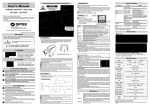
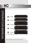
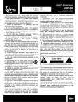
AK80
STEREO AMPLIFIER
User's manual
ED-3G-MA-060724-001
PRECAUTIONS
Thank you for purchasing our products. Please read this manual carefully for
your correct operation of this equipment, and keep this manual for future
reference.
For your safety please don't open the rack to avoid electric shock due to high
voltage inside. Consult professionals for maintenance help.
Keep the instrument off rain or humidity.
This instrument must work in places with good air flow.
Please check whether local voltage supply can meet the requirement of this
instrument.
Please pull out the plug when this instrument is not in use for a long time.
Load must be configured following this manual. Don't let the instrument work
overloaded for a long time.
TABLE OF CONTENTS
INTRODUCTION
INSTALLATION
Features
Signal Cables
4
Front Panel
5
Rear Panel
6
Speaker Cable Connection
Input Connection
Speaker Cable Connection In Stereo Mode
Speaker Cable Connection In Mono Mode
Speaker Cable Connection In Bridge Mode
7
OPERATION
ADDITIONAL
DESCRIPTION
4
7
8
8
8
9
Safety Instructions
Technical Specifications
Accessories
10
11
11
INTRODUCTION
Please read this manual carefully before you begin to use this instrument, and
keep the manual for future reference.
FEATURES
Ultra compact design, convenient for use.
Completely concealed adjustment button design, effective for status protection.
Adopting the amplification circuit targeting high sound quality, excellent in
expressing musical details.
Very low distortion.
Full protection function & high reliability.
SIGNAL CABLES
White
Red
4
When connecting with RCA connectors,
please ensure that the red connector is
plugged in the red socket, and the white
connector in the white socket.
FRONT PANEL
1
Bass Adjustment for L/R Channel
Turn this knob clockwise( )/anticlockwise( ) when you feel the bass
volume is not enough/too much.
2
HF Adjustment for L/R Channel
Turn this knob clockwise( )/anticlockwise( ) when you feel the
HF volume is not enough/too much.
3
Power Supply Indicator
This indicator will be on when
the power is turned on.
AK80
ON
SIGNAL
LEFT
RIGHT
MONO BRIDGE
BASS
TREBLE
OFF
STEREO PRO AMPLIFIER
POWER
4. Power Supply Switch
Power will be switched on/off when you
press ON/OFF end of this button.
5. R Channel Volume Adjustment
(Volume Adjustment for Mono Bridge Mode)
Volume of R Channel (in Mono / Bridge Mode)
is increased/reduced by turning this knob
clockwise( )/anticlockwise( ) .
6. L Channel Volume Adjustment
(Volume Adjustment for Mono Bridge Mode)
Volume of L Channel (in Mono / Bridge Mode)
is increased/reduced by turning this knob
clockwise( )/anticlockwise( ) .
7. Signal Indicator
The indicator will be on when there is stereo or
mono (in bridge mode) signal input.
REAR PANEL
2
Signal Input Socket for L Channel
3
Signal Output Socket for L Channel
4
Positive Terminal for L Channel Power Output
5
Positive Terminal for R Channel
Power Output
PARALLEL
STEREO
BRIDGE
CAUTION
BRIDGE
STEREO DIGITAL KARAOKE AMPLIFIER
MODEL NoA K80
POWER 8/ 28 0W
4/ 11 20W
8/ 12 40W(BRIDGE)
AC Rating:~110v/~220v,50/60Hz
RISK OF ELECTRIC SHOCK
ELDER AUDIO MANUFACTORY
R
+
6
DO NOT OPEN
R
L
L
+
AC 220V/50Hz
Fuse T2A/250V
OUTPUT
INPUT
L
L
R
R
PARALLEL
BRIDGE
Negative Terminal for R Channel
Power Output
7
Negative Terminal for L Channel
Power Output
8
Mode Switch
Turn this switch you can select stereo, mono,
or bridge mode.
9
Full Range/Low cut Switch
Turn this switch you can select between full range
and low cut status.
10
LF LIFTER (100Hz)
Power Supply Socket and fuss box
Power supply: AC220/50Hz, no other option is suitable
Fuss: T250V/IA( 5x20mm)
Please purchase parts for maintenance according to the above specifications.
FULL RANGE
1
Signal Output Socket for R Channel
11 (Mono / Bridge Mode) Signal Input Socket for R Channel
6
INSTALLATION
SPEAKER CABLE CONNECTION
1.Push down the eject button to open the cable
clip and insert the cable end in the hole.
2.Let the clip resume its original status, ensure
the cable end is tightened. Select suitable
speaker cable before connecting.
This amplifier can be connected to two clusters of speakers. Please check
whether the polarity of the speaker cables is correct. Incorrect connection
with reversed polarity will cause unnatural sound and bass loss.
Attention: Jut of cable end cannot touch adjacent cable.
RISK OF ELECTRIC SHOCK
DO NOT OPEN
Signals can be
accessed via
the output port
LD
DVD
+
Recorder or
loudspeaker
equipment
R
ELDER AUDIO MANUFACTORY
R
L
L
+
AC 220V/50Hz
Fuse T2A/250V
LF LIFTER (100Hz)
PARALLEL
STEREO
BRIDGE
CAUTION
BRIDGE
STEREO DIGITAL KARAOKE AMPLIFIER
MODEL NoA K80
POWER 8/ 28 0W
4/ 11 20W
8/ 12 40W(BRIDGE)
AC Rating:~110v/~220v,50/60Hz
FULL RANGE
INPUT CONNECTION
OUTPUT
INPUT
L
L
R
R
PARALLEL
BRIDGE
VCD
AUX
Signals can be accessed from LD, DVD, VCD, or AUX.
INSTALLATION
SPEAKER CABLE CONNECTION IN STEREO MODE
The mode switch must be located to "Stereo " .
SPEAKER CABLE CONNECTION IN MONO MODE
The mode switch must be located to "Mono " .
SPEAKER CABLE CONNECTION IN BRIDGE MODE
The mode switch must be located to "Bridge" .
8
OPERATION
The amplifier is ready for use when you finish connecting it to speakers and
plugging in the signal connector following the manual. Here are the instructions
for correct operation of the instrument:
1. Switch on the power (4) (see page 5).
2. Adjust volume
Adjust volume in stereo mode:
Turn the L channel volume knob (6) with a slotted screwdriver clockwise/anticlockwise
to increase/reduce the volume until you feel satisfied.
Turn the R channel volume knob (5) with a slotted screwdriver clockwise/anticlockwise
to increase/reduce the volume until you feel satisfied.
Adjust volume in mode/bridge mode:
Turn the R channel volume knob (5) with a slotted screwdriver clockwise/anticlockwise
to increase/reduce the volume until you feel satisfied.
3.Tone adujustment
Adjust tone in any mode:
Turn the bass volume knob (5) with a slotted screwdriver clockwise/anticlockwise
to increase/reduce the volume until you feel satisfied.
Turn the treble channel volume knob (5) with a slotted screwdriver clockwise/anticlockwise
to increase/reduce the volume until you feel satisfied.
4.Feet installation
Optional feet are available for standing the amplifier.
You need not mount the feet if you want to install the amplifier in the rack of a case.
If you want to lay the amplifier on a desk or other horizontal surface you must
mount the feet according to the following steps:
1 Take out the (four) feet from the package.
2 Insert the feet in the mounting holes at the bottom of the amplifier
3 Insert the locking pins in the center of the feet.
ADDITIONAL DESCRIPTION
SAFETY INSTRUCTIONS
DO NOT OPEN THE COVER
Do not open the cover to avoid the risk of electric shock caused
by high voltage parts in the product. Any problems caused by
user's wrong actions are out of warranty.
DO NOT DAMAGE THE POWER CORD
Please hold the plug when pull out or plug in the cord. Do not
pull out or touch the cord with wet hand, or it will cause the risk
of electric shock. Power supply cords should be routed so they
are not likely to be walked upon or pinched by items placed on
or again st them. When removing the cord from a power outlet
be sure to remove it by holding the plug attachment and not By
pulling on the cord.
AVOID OBJECT AND LIQUID ENTRY
Take care that objects do not fall into and that liquids are not
spilled into the inside of the product . If the object or liquid enter
the product , please ask qualified personnel to check it.
ABNORMAL STATUS
In the event of abnormal noise and smell, please put off
the power supply and pull out the cord, please ask
qualified personnel to check it.
NONUSE FOR A LONG TIME
When nonuse it for a long time, please put off the power
supply and pull out the cord to avoid the unexpected
dangers.
10
ADDITIONAL DESCRIPTION
TECHNICAL SPECIFICATIONS
Distortion Limit Output Power:
2x80W (THD+N: 0.5%, with 8
load, in stereo/mono mode)
2x120W (THD+N: 0.5%, with 4
240W (THD+N: 0.5%, with 8
Frequency Response:
load, in stereo/mono mode)
load, in bridge mode)
20Hz~20KHz(+/-3dB)with low-cut switch at GENERAL location
100Hz~20KHz(+/-3dB)with low-cut switch at LOWCUT location
Load Impedance:
8
(in mono/stereo mode), 4
8
(in bridge mode)
Harmonic Distortion:
0.03
Intermodulation Distortion:
0.05
Slew Rate:
12V/ S
Damping Factor:
200
Signal to Noise Ratio:
100db
Minimum Electromotive Force:
1V
Overload Electromotive Force:
8V
HF Compensation:
6dB(10KHz)
LF Compensation:
6dB(100Hz)
Dimensions(WxDxH):
430x160x43.8mm(without feet)
Net Weight:
5.6Kg
(in mono/stereo mode),
ACCESSORIES
Please check whether the accessories are complete after you open the
package according to the list below:
Feet
4pcs
User's manual
Warranty card
1pc
Certificate
1pc
1pc
MAINTENANCE
The equipment can be cleaned with dry cotton cloth. If the equipment is
abnormally dirty, please clean it with a piece of cotton cloth dipped in detergent
for 5 to 6 seconds, and finally dry it with a piece of dry cloth.
Don't use alcohol, insecticide, or any other volatile or corrosive liquid to clean
the equipment, which will cause colour fade or flake-off of the equipment surface.
When the equipment is not used for a long time, please keep it in an appropriate
dry place.
STEREO AMPLIFIER
www.elderaudio.com