Transcript
Non-Contact Thermometer
User's Manual
®
THERMO-HUNTER
BA-30TC
BUILT-IN2
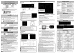
Name and Usage of Each Product Part
Trouble shooting
3. Measurement
qTurn the unit on after checking to see there are no mistakes in connection.
The LCD display will light up.
wPress the laser switch, and the laser marker will light up. Check to see that the
laser is aimed at the center area of the object to be measured. The laser marker is
aimed at the center of the area to be measured. Press the laser switch again to
turn it off or wait 20 seconds, and it will automatically turn off.
eFollow each step in "4. Setting."
rCheck to see if the unit is operating normally.
CAUTION
DO NOT STARE INTO BEAM
LASER DIODE POWER MAX1.0mW
WAVE LENGTH670nm
CLASS2 LASER PRODUCT
BA-06TC
4. Setting
Thank you for purchasing Optex products.
○Please check to make sure the model you purchased in the model you specified.
○Please read the manual before using the "Thermohunter Built-in 2" in order to use
it correctly.
○After reading the manual, please be sure to keep it for future reference.
Menu bar
qtake off the cover.
wPress the △/▽button to move the
menu bar, and set it to the positon
you want. At this time, the flashing
numerical figure will show the
current setting figure.
Laser switch turns on
red, when the laser is
emitting or the Relay
output is in operation.
5-8-12 Ogoto Otsu Shiga 520-0101 Japan
TEL.+81-77-579-8680 FAX.+81-77-579-8199
"Take Care of Environment."This manual uses recycled paper.
PRINTED IN JAPAN 1034-4 2008/2
Safe Usage
This user's manual contains various warnings to ensure safe usage of the product
and prevent damage and injury to you and other persons. Please be sure to heed the
warnings and strictly follow safety procedures.
CAUTION
This symbol signifies that improper usage may result in injuries or damage.
1. Installation
1. Please firmly install using the attachment screw holes on the lower section of
the main unit while strictly following the warnings below. Please use the M4
screws provided. When using screws sold on the market, please do not use
attachment screws over 8mm in length.
:This symbol signifies a prohibited action.
:This symbol signifies a required action.
CAUTION
Please don't look at the laser directly or aim it toward the eyes.
The laser may cause eye injury
or damage to your health.
CAUTION
This product is not a clinical
thermometer and therefore, cannot be used medical purposes.
Environmental Warnings
KEEP THE THERMOMETER AWAY FROM DIRECT SUNLIGHT, DUST, HIGH
TEMPERATURES AND HIGH HUMIDITY DURING USE AND STORAGE.
Otherwise, the optical lens will become dirty or damaged. Such usage or storange
will result in incorrect measurements.
DO NOT APPLY SUDDEN CHANGE OF ENVIRONMENTAL TEAPREATURE
TO THE THERMOMETER.
Sudden temperature changes of environments may cause incorrct measuring results.
In such cases, leave the thermometer for a moment to let it return to a stable condition
prior to the next measurement.
KEEP THE THERMOMETER AWAY FROM PRODUCS WHICH PRODUCE
STRONG ELECTROMAGNETIC WAVES. DO NOT USE IN AN ATMOSPHERE
CONTAINING CORROSIVE GASES OR EXPLOSIVE GASES.
™It is possible to angle the product by 45 degrees upward/downward or left/right if
the provided attachment fittings are used. The two taps of the attachment fittings
are the tripod attachment screws(W1/4). By screwing the attachment fittings onto
the main unit, the product can be attached the tripod.
Installation Warnings
qPlease install the unit so that the product is perpendicular to the object to be measured.
wPlease install the unit so that the cover can be attached and removed.
ePlease install the unit so that the main unit doesn't vibrate or receive shocks.
rPlease check to make sure that there are no sources of heat near the main unit or object
to be measured. Highly reflective objects may cause discrepancies in measurement.
tPlease install the unit in a location which isn't subject to deirect hot air and where
surrounding temperatures do not exceed 50℃.
2. Connection
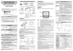
1. Please make the connections correctly as shown in the illustration below while
strictly following the warnings.
Connection Diagram
Usage in such environments will cause irreparable dameges to the unit and incorrect
maesurements.
Usage Warnings
AVOID MEASURING SHINY OBJECTS.
Shiny object reflect surrounding tempretures. The emissivity rate of the unit can
be adjusted to compensate for this probblem.
DO NOT USE WITH NON-STANDARD VOLTAGE.
Using the unit out of DC 12∼24 voltage range may result in damage to the
unit, shorts, fires and injuries. In such cases, immediately switch the unit off.
DO NOT TOUCH TO THE OBJECTS THAT IS BEING MEASURED.
The unit is a non-contact thermometer. Touching the unit to objects with high
temperatures will result in irreparable damages in the shape of the unit and incorrect measurements.
△button
DO NOT TOUCH THE LENS.
Do not thoch the lens with hard or sharp objects. Do not insert foreign objects
into the light receiving part. Otherwise, damage to the lens or incorrect measurements will occur.
DO NOT USE NEAR ELECTRIFIED OBJECTS.
Otherwise, irreparable dameges or incorrect measurements will result.
:Conduct a conventatiol measurement
:Set the temperature (real temperature) of the object to be
measured. Calculate the emissivity ratio from the real
temperature. Automatically adjust the set figure of the emissivity
ratio.
ε
:Set the emissibity ratio of the object to be measured.ε=1.20∼0.10
Adjust the measurement value according to the set emmissivity ratio.
DELAY
:Select the response time. Set figure 1∼200 (0.5∼10 seconds)
Smoothing is possible if setting when the display fluctuates or
when you wish to see (produce) the average figure.
°
C/°
F
:Switch between temperature displays. (BA-06/30TA only)
HI/ON :Setting Relay output. When the measuring value rises above the
preset value, Relay output is on.
LO/ON :Setting Relay output. When the measuring value is lower than the
preset value, Relay output is on.
ePress the ENTER button to put into "SET MODE". For the TEACH and emissivity setting, the laser marker lights up.
rPress the △/▽ button to change the set figure. At this time, the figure which is
displayed alternately with the set figure represents the operand temperature of
the set figure/value.
tPress the ENTER button to record. At this time, the blinking numerical figure,
etc. represents the set figure after change.
yPress the △/▽ button to return the menu bar to the MEAS. position and put
into "MEASURE MODE." The unit will automatically retun to "MEASURE
MODE" if no buttons are pushed for a period greater than 10 seconds. At this
time, setting is invalid.
※ Analog output produces a measurement figure during setting.
qRelay output setting
qMove the menu bar to HI/ON or LO/ON, press the ENTER button.
wPress the △/▽ button to change the pre-set value for Relay output and press the
ENTER button to fix the value.
ePress the △/▽ button to set ON (ffective) or OFF(ineffective), and press the ENTER
button. In case of ON, the Relay output is effective, after
the ENTER button is pressed.
※When Relay output is effectice, Enter button turns on. If
the preset value of HI is set lower than of LO, the Relay
output is effective when the Thermometer shows the
measuring value within the range preset value between
LO and HI.
TEACH Function
This is the function is case that the emissivity ratio of objects is unknown. Firstly, measure
the temperature value of the target with Thermocouple, etc, then enter the result(temperature value measured)into Teach Mode. After the process, the emissivity ration is
automatically calculated and Thermometer shows each measuring value according to the
ratio. Teach-in function is not available while the display blinks or shows ERR. Use direct
input of ε-value.
Emissivity ratio (ε)
The emissivity ratio is the rate of the energy emmited form the suface of the object. All
objects possess a particular emissivity ratio which changes according to the object's
surface conditions or tempreature. Since the unit allows the emissivity ratio to be set,
even more precise measurements can be conducted by matching the emissivity ratio of
the object to be measured.
Objects with a low emissivity ratio(e.g. the surface of shiny metallic objects) reflect the
surrounding tempreture since they are highly reflective. In this case, it is necessary to
block out these effects from surrounding objects since incorrect measurements will result
by reflecting these temperatures.
The emissivity ratio normally has a maximum value of 1.00.
However, taking into consideration the influence of surrounding noise, the unit can be set
up to 1.20.
Maintenace
Connection Warnings
qUse the unit within rated voltage and confirm prpoer wiring sufficiently for the connection.
wDo not short-circuit Relay output with another output cable.
eAs photo MOS relay is used for the relay output, it is isolated from a circuit. On-resister
is 2.5Ω or less.
rIn case of using the unit in the strong EMI noise environment, it is necessary to run the
output cable through an iron pipe, etc, as a precausion.
Main Unit
Calibration
Check the power voltage and adjust it to
the DC12∼24V range.
Clean the lens referring to the Lens
section under "Maintenance".
Clean the lens referring to the Lens
section under "Maintenance".
Adjust the laser marker so that it is aimed
at the center of the object to be measured.
Near the object to be measured is Block the heat source using a board, etc.
▽button
MEAS.
TEACH
Lens
Solution
Check the lead wires and the connections.
another object emitting high temperatures, affecting the temperature
reading.
ENTER/LASER switch
OPTEX CO.,LTD.
Problems
Cause
Display doesn't appear The power source is not
connected properly.
The power voltage is
low.
Laser doesn't ap-pear, The laser emitting
it is dark.
aperture is dirty.
The measured figure is The lens is dirty.
odd.
The measuring area is
off center.
Dust, dirt and scratches on the lens cause incorrect measurements. In case
of dirty lenses, please remove the dust on the lens with a blower, etc. for lens
cleaning use. If the dust or dirt can not be removed with a blower, lightly wipe
the lens with a cotton swab or special lens cleaning cloth using a little ethanol
alcohol.
The main unit is made of PBT and polycarbonate. When it becomes cirty,
lightly wipe caustic soda, ammonia, acetane, thinner, etc. to clean the dirt off
since these chemicals will permeate the surface and melt it.
We recommend a regular calibration. Please inquire at your distributor where
you bought the unit.
The measured figure is
not stable.
Impossible to teathin.
(ERR)
The emissivity ratio
setting is off.
The unit is vibrating.
The temperature of the
unit changes suddenly.
Unproper setting
Reset to the emissivity ratio of the object
to be measured.
Prevent the vibration.
Put the unit aside for a while to stabilize
the unit's temperature.
Confilm again the setting value, or input ε
value directly.
If the above solutions do no correct the problems or should othre problems not meneioned
above occur, please contact your distributor.
Field of View
●BA-30TC
●BA-06TC
* The laser marker is aimed at the center of the measuring area.
* The optical resolution values stated in "Field of View" are at 90% energy.
* The size of measuring object should be sufficiently larger than the "Field of View"
(spot size) shown in the above illustration.
Specifications
Model
Temperature Range
Area Size
BA-06TC
BA-30TC
0∼500℃(display −20∼520℃)
φ6/200mm
φ30/1000mm
Optics
Silicon lens
Spectral Response
Thermopile/8∼14μm
Response Speed
500ms/90%
Accuracy
±1% of reading value or ±2℃ ±1digit, whichever is greater(ε≒1.0)
Repeatability
±1℃ of reading value
Display Resolution
1℃
Relay output
Photo Mos relay output, 350mA・DC100V Max
Output Renewal Time
50ms
Focus
Coaxial laser marker
Emissivity ratio(ε)Adujustment
0.10∼1.20
Delay Function
Nominal 1∼200(0.5∼10sec) variable
Power Supply
DC12∼24V±10%/MAX150mA
Ambient temperature
0∼50℃
Environmental Humidity
35∼85%RH(without dew condensation)
Storage Temperature
−10∼60℃
Vibration Resistance
3G(20∼50Hz, according to JIS CO911)
Water Resistance
IP65
Materials
Ring case:glass-containing PBT, Rear:PSF Cover:PC
Weight
360g
Accessories:Attachment Fitting ×1, M4 screw ×2
Opitional accessories:Air purge collar:BA-AP1
*Design and specifications are subject to change for product improvement without prior
notice.