1
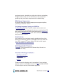
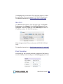
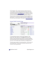
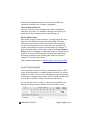
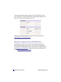
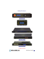
Web Power Switch 7
USER’S GUIDE
Product Features
Congratulations on selecting the DLI Web Power Switch, a
surge-suppressed, AC power switch with automatic reboot and
programmable power control. Features include:
Simple Web Interface
The internal web server is accessible from any standard browser.
Simply enter an IP address. The controller may be configured and
controlled via the web.
Auto-Ping Reboot
This automatic feature monitors a remote IP address. If a server,
router, or other peripheral goes down, the switch will automatically
reboot it, without user intervention. Up to 8 devices can be
monitored individually.
8 Switched Outlets + 2 Unswitched Outlets
Eight individually switched controlled circuits are provided with
single outlets. Outlets are spaced for large adapters and plugs.
Un-switched outlets are provided for “always on” devices.
LCD Display
A 2x16 LCD displays status for each outlet. Custom messages
can be displayed using a simple scripting language.
Password Security
Multi-user password security is provided to limit access to the
power controller. The administrator selects which outlets each
user controls.
Sequenced “On Timer”
A programmable delay timer allows outlets to be switched on in
sequence, rather than simultaneously. Most devices draw more
power when they are initially switched on. Using this timer, more
2
Web Power Switch 7
digital-loggers.com
equipment can be attached to a single circuit without overloading.
Programmable scripts can also be used to create customized
power-up and power-down sequences with variable timing.
MOV Surge Suppression
A 3600W metal oxide varistor clamps power surges and spikes,
protecting all attached devices.
Scripting Language, Syslog, and Utilities
A scripting language can be used to create custom control and
reboot sequences, schedule periodic reboots, customize the LCD,
and control serial devices. Both internal and external system logs
are provided. Windows utilities send status notifications, warnings,
and power bills via email.
New Features
New features include a larger keypad, extended real-time clock
battery life, scheduling function, removable power cord, Wake on
Lan (WOL) support, NTP sync, Apple iOS and Android support.
Learn more about new features here.
Field Upgradeable Firmware
Firmware is field upgradeable via Ethernet using the web or a
command line utility.
Standard Package Contents
•
•
•
•
Web Power Switch 7
Power Cord
Registration Card
Manual
Please contact the shipping carrier immediately if your package
appears opened or damaged in transit. Call DLI at (408) 330-5599
for tech support, service, and hardware upgrades.
Web Power Switch 7 3
Important Factory Defaults
DEFAULT IP ADDRESS
The factory default is 192.168.0.100
DEFAULT ADMINISTRATOR LOGIN
User name: admin (lower case)
Password:
1234
To reset the IP address and admin login to factory defaults, gently
press the reset-to-defaults button to the left of the LCD.
Note: Reset-to-defaults sets the admin login and IP address, but
it doesn’t affect outlet names, links, and stored scripts. Auto-Ping
and auto-start of custom scripts are disabled.
Quick Setup
Use these shortcuts if you are an experienced installer. If this is
your first time, please skim the entire manual first.
1. Remove the switch from its shipping carton. Save the
carton and packing for future hardware upgrade.
2. Attach the power cord to a protected power source with a
capacity of at least 15 amperes.
3. Attach the cable from the controller to a port on your
4
Web Power Switch 7
digital-loggers.com
4.
5.
6.
7.
8.
LAN. Switch power on. If you are connected to a switch,
you may need to cycle power to the switch to establish a
connection.
Ping the default address: 192.168.0.100 to confirm a
network connection is established. If you don’t receive a
response, see the IP Setup section below.
Log in to the power controller using the default user name
admin and the password 1234
“admin” must be entered in lower case.
Click on the Settings link to reach the configuration page.
Select the safest power-loss configuration for your
installation: (all OFF, all ON, or pre-powerloss)
Configure the power switch as described below. After
each change, click Submit and wait for the page to refresh
before continuing.
Tips:
•
A three-bulb electrical safety-tester is handy for configuring
the controller before attaching your equipment.
•
Please register your product for better support and free
firmware updates
IP Setup
If your network settings won’t access the default IP, use a direct
cable connection (temporarily bypass any switch or router)
and follow these steps to add a compatible static IP such as
192.168.0.50 Before adding an IP, close programs and browsers.
After the link is established, you can revert to DHCP if desired or
use a combination of DHCP and static IPs.
Web Power Switch 7 5
Windows Step 1
In Windows, the first step is locating the network adapter TCP/IP
properties. The procedure differs for each Windows version:
Windows XP, 2000, 2003: Open Start / Control Panel / Network
Connections. If you’re using “classic view”, it’s Start / Settings /
Control Panel /Network Connections. Right-click on Local Area
Network Connection and select Properties. Proceed to step 2.
Windows Vista: Open Start, right click on Network, then on
Properties. Double click Network and Sharing Center, click
Manage Newtork Connections. A Network Connections window
appears. Right click on the network connection to the switch, ie.
Local Area Network. Proceed to step 2.
Windows 7: Open the Start orb, click on Control Panel. Use the
default Category View. Click View Network Status and Tasks,
then Change Adapter Settings. Proceed to step 2
Windows 8: Mouse or swipe to the bottom right corner. Select
Settings. Select Control Panel. Use Category View. Select
Network and Sharing Center. Change Adapter Settings. Right
click on the connected network and select Properties. Go to step 2
Windows Step 2
The second step is adding an IP such as 192.168.0.50. If you are
using DHCP, it’s easiest to temporarily disable it while configuring
the switch.
Select Internet
Protocall TCP/IP
V4 Properties and
click Properties.
Enter a compatible
static IP such
as this:
6
Web Power Switch 7
www.digital-loggers.com
Click Apply and close windows. Ping the power switch to confirm
the connection. Point your browser at 192.168.0.100 and log in.
Find detailed instructions at digital-loggers.com/ip_setup.html
Max OS X
Turn AirPort off temporarily. Click the Apple logo, then System
Preferences, then Network. Select Built-In Ethernet and then
Configure. Under the TCP/IP tab, select Manually and enter an
IP address sucha s 192.168.0.50 as shown:
Make changes shown.Point your browser at 192.168.0.100 and
log in.
Find detailed instructions at digital-loggers.com/mac_ip_setup.pdf
Basic Operation
After power-up, the controller performs a sequence of self-tests to
ensure reliability. Network settings on the Settings page are used:
Web Power Switch 7 7
The IP address of the controller needs to match the “class C”
of your system. In other words, the first three bytes (192.168.0)
must be the same as the IP address on your computer in order to
access the controller. Using a Ping utility is a good way to confirm
you have a valid network configuration. A gateway setting is
Once you have a connection, the controller may be operated via a
web browser. To access the controller, enter the IP address in the
URL field of your web browser. The default is http://192.168.0.100.
Home (Outlet Control) Page
To access the home page, first enter the IP address in web
browser URL field, then log in. User admin has access to all
features. Other users have limited access to outlets as assigned
by the administrator. When configuring the power controller for the
first time, use the default admin username and 1234 password.
The home page contains 13 external hyperlinks. The first nine are
fixed internal links: The four links in the lower left corner of the
screen are user-programmable.
8
Web Power Switch 7
digital-loggers.com
Outlet Control
Clicking “Outlet Control” links to the home page used for
manually switching outlets on and off. Access to specific outlets is
determined by your login. User admin has access to everything.
Setup
The setup page lets you select outlet names, program web links,
startup delays, and the power loss recovery mode. You can also
change login credentials on this page.
Scripting
A scripting language using BASIC commands lets you
customize the power controller. Scripts may be started manually,
automatically on power-up, by external http commands, or by
Auto-Ping events. Find a full list of commands and example scripts
at: digital-loggers.com/scripting.html
Auto-Ping
The Auto-Ping link lets you set parameters for automatically reboot
attached equipment. First specify an IP address to ping. Next
adjust the timing settings and use the checkboxes to link the IP to
specific circuits. For example, if a router is unreachable, you may
choose to automatically reboot both a router and a switch attached
to two different circuits. Learn more: digital-loggers.com/auto-ping.
html.
System Log
The power controller keeps a log of system events including logins
(successful and attempted), outlet switching, power interruptions,
and Auto-Ping events. Recent events are stored in the log
and accessible from the System Log page. Multiple controllers
can export logs to a single external SYSLOG server. For more
information on syslog: digital-loggers.com/syslog.html
Logout
The controller will automatically log-out when your browser
session is closed. Click this link to log-out in advance.
Web Power Switch 7 9
Help
The Help link displays the latest online manual. Since features
are subject to change without notice, this manual may not be an
exact match for earlier controllers and earlier firmware versions.
Find the firmware revision history here.
Programmable Web Links
Four additional user-defined web links are provided on the outlet
control page. Factory defaults are Manual, FAQ, etc. You may
change the name and destination URL for these links on the
Settings page. These links are convenient for connecting to
other power controllers or to remote sites.
Switching Outlets On and Off
The outlet control page lets you control any outlet (except the
always-on pair). A master setting also allows users (with security
access) to switch all outlets on or off.
To switch an outlet on or off, simply click to the right of the outlet
name or number. Switching is immediate.
Use the keypad for local control: Select an outlet using the
arrow keys, then press on, off, or cycle. Press ON or OFF for
5 seconds to lock or unlock an outlet. Locking prevents web
access.
You may also Cycle a device which is connected to the
controller. This feature is useful for rebooting Ethernet devices
which may interrupt the web link to the controller. Clicking Cycle
switches power off, waits for the ON Delay time, and then
switches power back on. This reboots the attached device.
10 Web Power Switch 7
digital-loggers.com
You can also cycle all outlets
using the Master Control on the
bottom of the page. An adjustable
ON sequence delay takes effect
when cycling, when using All
Outlets ON and on power-up.
Depending on your web browser settings, you may need to click
the Refresh button or F5 key to update the on-screen status
display after changing settings. Screen refresh rate is adjusted in
two places: on the Setup page and in your browser settings.
Setup Page
The Setup page allows the administrator to configure the power
controller. These settings are supported:
Controller and Outlet Names
Use the controller name field to assign a Controller Name to the
power controller itself. Examples are Server Rack 4 PDU or
Phone Room Power Switch. The Controller Name appears on
top of all pages. Assign a separate name to each outlet, such as
DSL Router 1 or Backup Email Server to aid identification. Check
the Confirm check box to the right of the outlet name if you would
like a pop-up window to appear before switching critical outlets.
Power-On Sequence Delay
The power controller will pause for a period specified in the All ON
Sequence Delay before switching each outlet on. This delay helps
prevent power surges and blown circuit breakers which can occur
when multiple devices are switched on simultaneously. A delay of
60 seconds is suggested for server applications. This delay value
is also used in the Cycle function.
You may also enter a screen refresh delay in this section. If Enable
screen refresh is checked, and a delay value is entered, your
browser should periodically update the status screen.
Wrong Password Lockout
Web Power Switch 7 11
After three failed login attempts, the switch can disable access for
a selected period of time (0-60 Minutes).
Power Loss Recovery Modes
The power loss recovery mode setting has three settings which
take effect after a power failure:
1. You can turn all outlets off (all systems will be switched off
until manually turned on later).
2. You can automatically turn all outlets on using the All ON
sequence delay timer described above.
3. You can return to the same outlet settings that were
used prior to the power loss. ie. 1 On, 2 Off, etc. The ON
Sequency delay timer is used.
Note: If you have written a script and enabled scripting, the script
will start automatically on power up at LINE 1.
User Defined Links
You may link to other power controllers, your own web pages, or
remote web sites by entering up to four URLs and descriptions in
the Setup page. For example, enter “Site Two Power Controller”
in the description field with a URL of “192.168.0.250” These links
appear on the home page.
Access Control
The administrator can restrict user permissions to certain outlets.
To set permissions, login as admin, then create a permissions
matrix by entering user names on the left and checking permitted
outlets to the right of each user name.
Network Settings
A valid fixed IP address, network mask, and gateway must be
entered in this section.
12 Web Power Switch 7
digital-loggers.com
When changing IPs, you may need to restart your network
switch to validate the new IP on an “auto-configuring” switch
port. Be sure to record the new IP address.
Use the Protect button to lock the network
settings. Once protected, the network settings
cannot be changed except by pressing the
physical reset button below the LCD.
Auto-Ping
TM
Auto-Ping Operation and Settings
Auto-Ping is an automatic system for rebooting IP equipment
without human intervention. Auto-Ping will monitor a device. If
it stops responding, Auto-Ping will cycle power to reboot it. For
example, you might use Auto-ping to monitor an external multicast IP to automatically reboot a DSL router or WiFi AP.
To use Auto-Ping, first add an IP address. Next, link that
IP address to one or more outlets. Timing settings must be
considered.
Add IP Address to Auto-Ping
Use this option to specify the address of an IP device you
wish to monitor. After entering the IP address, the settings
page will refresh and you can select the outlets associated
with this address. Use the checkboxes in the Auto-Ping
section to correlate the IP address to one or more outlets. If
communications to the target IP is lost, these outlets will be
rebooted. Four parameters control Auto-ping operation:
Time between pings
This is the time between each “ping” check of the IP address. 60
seconds should be useful for most applications.
Ping failures before reboot
This sets the number of failed communications attempts that
must be sequentially detected before a power cycle. For
example, when set to 5, the target system must fail to respond
5 times in a row before it is rebooted. Since occasional network
Web Power Switch 7 13
timeouts and packet loss can occur during normal Ethernet
operation, between 5 and 10 pings is suggested.
Times to Attempt Reboot
Limit the number of times a target device will be rebooted by
entering a value here. For example, entering 5 will reboot your
server up to 5 times before giving up and leaving it on.
Device Reboot Delay
After power cycling to reboot a device, a waiting period will occur
before the IP address is re-checked by Auto-ping. This delay
allows the device time to reboot. Most devices take some time
to reboot. Windows and Linux servers can force automatic file
system checks which may take several minutes to complete. To
allow for startup delays, enter a time delay in the Device Reboot
Delay period. For example, a reasonable value for a typical server
might be 10 minutes (600 seconds). Entering 600 would cause
the power controller to start checking the server for normal IP
operation 10 minutes after reboot.
Find a detailed explanation at: digital-loggers.com/Autoping.html
Auto-Ping Example
In this example, we use Auto-Ping to automatically reboot a DSL
router. Since the switch is connected inside the router, we select a
target IP of 8.8.8.8. This is a multi-cast address which connects to
a multidude of Google name servers. We can safely assume that if
none of them respond, we have lost network connectivity.
We connect the router to outlet 1, and add the external IP here,
leaving all timing values at defaults. We first add the IP here:
14 Web Power Switch 7
digital-loggers.com
After clicking the green checkbox, Auto-Ping will check for several
responses before enabling itself. After that, the router will be
monitored and automatically rebooted.
Had we entered a number in the Script box, a program would
be excuted (starting at that line number) when the target router
required reboot. Find more examples at:
digital-loggers.com/Autoping.html
Mobile Device Access
The power controller will automatically “zoom” webpages to fit
smaller mobile device screens. To use this feature, first log-in as
admin. Then create a user such as “mobile”. The webserver will
auto-detect the screen size of the mobile user. This feature is
not avilable when logged in as admin. The larger admin pages
require a full-size screen. A number of third-party applications are
available to control the switch from Android and IoS. Find more
information here: digital-loggers.com/mobile.html
Real-Time Clock
The internal Real-Time-Clock (RTC) is provided. This clock can
be set manually using the Date/Time link. The time zone can be
selected based on GMT. To syncronize the clock to a networked
time standard, an NTP command is provided in the scripting
language. Internal batteries have an estimated 15-year lifetime.
Scripting Example
The controller can be used as-is in most applcations, or
customized using a BASIC scripting language. A full description is
beyond the scope of this manual, so please visit our website for
other examples and a full command list. Here’s a simple example:
a lighting economizer.
Web Power Switch 7 15
This simple program shuts the lights off at 9:30PM daily. Users
can turn them on using a web browser. Should they forget to turn
them off, the power switch takes care of it.
Find more scripting examples, and a full list of commands at
digital-loggers.com/Scripting.html
Windows Logging and Email Notification
A Windows utility can be used to record activity and notify you
when specified trigger events occur. This utility also logs power
consumption and generates reports when used in conjunction with
our larger power controllers. Learn more and download the utility
free at digital-loggers.com/pcl.html
16 Web Power Switch 7
digital-loggers.com
Specifications
Alert Beeper
73dBa at 12”. Programmable.
Applications
Commercial, industrial, and residential remote
power control and reboot. Indoor use only.
Circuit Breaker
Manual reset, 15A Thermal, UL
Clock / RTC
15 year Li battery, NTP support
Control / Display
w/ PowerSave
Reset -to-factory-default switch, 2x16 Backlit LCD
Dimensions
Outside 1.6x5.8x13” 12.3”Between mtg. holes
EEPROM
512Kb I2C Standard
Enclosure
Aluminum chassis, double grounded. Injection
olded high-temp thermoplastic base plate.
Vented 2 sides.
Fanless.
Ethernet Interface
10/100 autosensing, Static IP, TCP port selectable,
8 pin RJ-45 w/ internal FCC filtering
FCC Testing
Part 15 S/D
Humidity
8-80% RH Operating
Input Power Cord
Removable C19 14AWG 6’ length standard
Inlet and Outlet Rating
UL, CSA 15A, 120VAC only
Input Frequency
Power supply - DC-400Hz
Operating Temperature -30º to 170ºF, -34º to 77ºC
Options - User
• Right-Angle 19” rack-mount bracket.
Power Supply Rating
90-240V, AC/DC Autosensing
Password Transmission Encrypted, base 64
Movable HTTP port for security
Power Dissipation
3.9W Typ Max (all on) <3 W idle
Power Fail Hold-Over
350ms minimum (all relays on)
Power-Up Modes
Last used settings, all power on or off, sequential
on or run BASIC program script
Relay Contact Spec
15-25A AC/DC, 1/2HP
Software Controls
Individual outlets on/off, all on/
off/cycle. Net settings, Web UI
Surge Protection
3600WMetal Oxide Varistor
Size (Single-Pack Carton) 2.4x7.7x15.8”
Weight (bare)
14
Single unit 3.6 lbs excl. cord & packaging.
Web Power Switch 7 17
Limited Five Year Warranty
The terms of this warranty may be legally binding. If you do not agree to the terms
listed below, return the product immediately in original unopened condition for a full
refund. The purchaser assumes the entire risk as to the results and performance of
the unit. DLI warrants this power controller to be free from major defects. No agency,
country, or local certifications are included with this unit. It is the responsibility of
the user to obtain such certifications if necessary for the customer’s application.
Buyer acknowledges and agrees that it is solely responsible for proper use,
certification and safety testing of components supplied by DLI. DLI’s entire liability
and exclusive remedy as to defective hardware shall be, at DLI’s option, either (a)
return of the purchase price or (b) replacement or repair of the hardware that does
not meet DLI’s quality control standards and has been returned through proper
RMA procedures. DLI’s liability for repair or replacement is to DLI’s customer ONLY.
WARRANTY SERVICE DOES NOT INCLUDE SOFTWARE OR HARDWARE
UPGRADES. No warranty service will be provided without an original invoice from
DLI and an RMA number provided by technical support. RMA material must be
shipped prepaid to DLI. RMA numbers are valid for 15 days from date of issue.
This warranty does not cover products modified, subjected to rough handling, or
used in applications for which they were not originally intended. Batteries are not
covered under warranty. Physical damage caused by customer or in transit to DLI
is not covered under warranty. No oral advice or verbal warranties made by DLI’s
employees, dealers, or distributors shall in any way increase the scope of this
warranty. DLI makes no warranty as to merchantability or fitness for any particular
purpose. DLI assumes no liability for incidental or consequential damages arising
from the use or inability to use this product. This warranty gives you specific legal
rights. You may also have other rights that vary from state to state. Since some
states do not allow the exclusion of liability for consequential damages, some of
the above limitations may not apply to you. Auto-PingTM is a registered trademark
of Computer Performance, Inc. Since this is a FLASH based product, firmware
should not be updated over the Internet or a busy LAN. Packet loss could result
in FLASH corruption, requiring mail-in service. This product is designed for indoor
use only. It is not intended for and should not be used in outdoor, mobile, airborne,
or FDA Class III applications.
DIGITAL LOGGERS, INC.
2695 Walsh Avenue
Santa Clara, CA 95051
FAX (408) 541-8459
digital-loggers.com
[email protected]
© 2013 DLI This product is protected by pending US patents and foreign patents
Release 1.6.D 4/15/2013
18 Web Power Switch 7
digital-loggers.com
Related Products:
Datacenter PDU
Web Enabled DIN Relay
-48V Smart Switch
Smart PoE Injector
Call (408) 330-5599
Web Power Switch 7 19
Auto-ping Function
Online Manual
Scheduling Function
Product Suggestions
BASIC Scripting
2695 Walsh Avenue, Santa Clara, CA 95051
Tel: (408) 330-5599, Fax: (408) 541-8459
digital-loggers.com