1
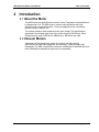
HR8 Ultrasonic Motor User Manual D/N: MSP8458000-01 REV: B Nanomotion Ltd. POB 623, Yokneam 20692, Israel Tel: 972-73-2498000 Fax: 972-73-2498099 Web Site: www.nanomotion.com E-mail: [email protected] August 29, 2012 HR8 Ultrasonic Motor User Manual Copyright Copyright This document contains proprietary information of Nanomotion Ltd., and may not be reproduced in any form without prior written consent from Nanomotion Ltd. No part of this document may be reproduced, translated, stored in a retrieval system or transmitted in any form and by any means, electronic, mechanical, photographic, photocopying, recording, or otherwise, without the written permission of Nanomotion Ltd. Information provided in this document is subject to change without notice and does not represent a commitment on the part of Nanomotion Ltd. Copyright April 2000-2012, January 2011, Yokneam, Israel. All rights reserved. Patent Information Nanomotion products are covered under one or more of the following registered or applied for patents. 5,453,653; 5,616,980; 5,714,833; 111597; 5,640,063; 6,247,338; 6,244,076; 6,747,391; 6,661,153; 69838991.3; 6,384,515; 7,119,477; 7,075,211; 69932359.5;1186063; 7,211,929; 69941195.5; 1577961; 4813708; 6,879,085; 6,979,936; 7,439,652; 7061158 ;1800356; 1800356; 1800356; 2007-533057 (pending); 2011-093431 (pending); 7,876,509; 10-2007-7009928 (pending); 200780019448.6 ; 7713361.9 (pending); 12/294,926 (pending); GB2008000004178 (pending); GB2009000003796 (pending); 12/398,216 (pending); GB2446428; 12/517,261 (pending); 08702695.1 (pending); 10-2009-7017629 (pending); 12/524,164 (pending); 12/581,194 (pending) Nanomotion Ltd. Page 2 of 41 HR8 Ultrasonic Motor User Manual Revision History Ver/Rev Date Details 00/A Apr 2000 New release. 00/B Sep 2008 Update manual. 01/A Jan 2011 Updated EOP tables. New format for the EOP graphs. 01/B Dec 2011 The graphs were standardized, as in all motor UMs. NA August 2012 Administrative change – Added patent information to front matter Nanomotion Ltd. Page 3 of 41 HR8 Ultrasonic Motor User Manual Limited Warranty Limited Warranty Nanomotion (hereinafter NM) warrants the product (other than software) manufactured by it to be free from defects in material and workmanship for a period of time of one year (except those parts normally considered as consumable/expendable components such as motor conditioning brushes). The warranty commences thirty (30) days from the date of shipment. NM warrants those parts replaced under warranty for a period equal to the remaining warranty coverage of the original part. NM’s sole and exclusive obligation under this warranty provision shall be to repair, or at its sole option exchange defective products or the relevant part or component, but only if : (i) the Purchaser reports the defect to NM in writing and provides a description of the defective product and complete information about the manner of its discovery within ten (10) days of its discovery; (ii) NM has the opportunity to investigate the reported defect and determines that the defect arises from faulty material, parts or workmanship; and (iii) the Purchaser returns the affected product to a location designated by NM. These provisions constitute the exclusive remedy of the Purchaser for product defects or any other claim of liability in connection with the purchase or use of NM products. This warranty policy applies only to NM products purchased directly from NM or from an authorized NM distributor or representative. This warranty shall not apply to (i) products repaired or altered by anyone other than those authorized by NM; (ii) products subjected to negligence, accidents or damage by circumstances beyond NM control; (iii) product subjected to improper operation or maintenance (i.e. operation not in accordance with NM Installation Manuals and/or instructions) or for use other than the original purpose for which the product was designed to be used. The warranty stands only when the motors are used with the NM drivers/ amplifiers. NM shall not in any event have obligations or liabilities to the Purchaser or any other party for loss of profits, loss of use or incidental, increased cost of operation or delays in operation, special or consequential damages, whether based on contract, tort (including negligence), strict liability, or any other theory or form of action, even if NM has been advised of the possibility thereof, arising out of or in connection with the manufacture, sale, delivery, use, repair or performance of the NM products. Without limiting the generality of the preceding sentence, NM shall not be liable to the Purchaser for personal injury or property damages. Nanomotion Ltd. Page 4 of 41 HR8 Ultrasonic Motor User Manual CE Compliance CE Compliance The motors and drivers comply to the following directive: Safety : IEC 61010-1:1990 EMC : 89/336/EEC as amended by 92/31/EEC and 93/68/EEC Harmonized Standards to which conformity is declared: EN 50081- 2:1993/EN 55011:1991 Generic Emission Standards Class A for radiated emission and Class B for conducted emission. EN 50082- 2:1995 Generic Immunity Standard NOTE: UHV motors are designed for convenient interface to the UHV setup. The motors are therefore supplied with three open electrical leads. Whereas standard motors comply with CE regulations and the UHV motors have the same internal design as standard motors, the UHV motors are supplied as components and CE conformity in both EMI and Safety must be implemented as part of the UHV system design. Nanomotion Ltd. Page 5 of 41 HR8 Ultrasonic Motor User Manual Preface This user Manual is designed to help the user in installing and operating the various types of Nanomotion’s HR8 Piezoceramic Motors. This manual assumes that the reader has a fundamental understanding of basic servo systems, as well as motion control concepts and applicable safety procedures. The manual describes the physical dimensions as well as the mechanical and electrical installation procedures for these motors. Warranty The motors are covered by warranty for a period of twelve months from the date of invoice. The following voids the warranty: Misuse or incorrect mounting, incorrect electrical connections, removal of motor cover or of serial number, modification of parts, and any other use that is not according to the cautions and warnings provided in this guide. Liability for replacement will be determined after inspection of any defective item by Nanomotion or an approved agent. Nanomotion Ltd. Page 6 of 41 HR8 Ultrasonic Motor User Manual Definition of Terms Table of Contents CE COMPLIANCE ................................................................................................................ 5 PREFACE ............................................................................................................................ 6 WARRANTY ......................................................................................................................... 6 1 DEFINITION OF TERMS.................................................................................................. 9 1.1 WARNINGS .................................................................................................... 9 1.2 CAUTIONS ............................................................................................................. 9 2 INTRODUCTION ............................................................................................................ 10 2.1 About the Motor .................................................................................................... 10 2.2 Vacuum Motors .................................................................................................... 10 2.3 HR8 System Parts ................................................................................................ 11 2.4 Handling ............................................................................................................... 11 2.5 Installation and Servicing ...................................................................................... 11 3 PREPARATION AND INSTALLATION.......................................................................... 12 3.1 Preparation ........................................................................................................... 12 3.1.1 Mounting Base ....................................................................................... 12 3.1.2 Limiting Stage Motion ............................................................................. 14 3.2 Motor Installation .................................................................................................. 15 3.2.1 Bonding the Ceramic Driving Strip to the Stage...................................... 15 3.2.2 Mounting the Motor ................................................................................ 18 3.2.3 Motor Grounding .................................................................................... 21 3.2.4 Motor Connections ................................................................................. 22 3.2.5 For Ultra High Vacuum motor: ................................................................ 24 3.2.6 Motor Run-In .......................................................................................... 24 4 SPECIFICATIONS ......................................................................................................... 26 4.1 General................................................................................................................. 26 Nanomotion Ltd. Page 7 of 41 HR8 Ultrasonic Motor User Manual Definition of Terms 4.2 Specification Parameters ...................................................................................... 28 4.3 Thermal Envelope of Performance (EOP) ............................................................. 29 4.3.1 Description ............................................................................................. 29 4.3.2 Stage Heat Dissipation Consideration .................................................... 30 4.3.3 Thermal EOP for HR8 Motor Driven by AB1A, AB2 AB4 Drivers ............ 31 4.3.4 EOP for HR Motors Driven by AB5, AB51 Drivers .................................. 33 4.4 Schematics ........................................................................................................... 38 4.4.1 Dimensions for Standard and High-Vacuum Motors ............................... 38 4.4.2 Dimensions for Ultra-High-Vacuum Motors ............................................ 38 4.4.3 Mounting Base Dimensions .................................................................... 40 5 CONTACT INFORMATION............................................................................................ 41 5.1 Customer Service ................................................................................................. 41 5.2 General Inquiries and Ordering ............................................................................. 41 Nanomotion Ltd. Page 8 of 41 HR8 Ultrasonic Motor User Manual 1 Definition of Terms Definition of Terms CAUTION: Identifies conditions or practices that could result in damage to this product or other property. WARNING: Identifies conditions or practices that could result in personal injury, damage to the product or other property. 1.1 WARNINGS • Do not remove the cover of the motor or disassemble its connector. High voltage inside. • Be sure to ground the motor to the electrical network ground (according to the following instructions) before operating the motor. 1.2 CAUTIONS • Arrows on motor indicate direction of motion. Align accordingly. • Do not set power-on unless motor is mounted and preloaded! • Do not immerse the motor in any liquid or cleaning agent. • Use only a clean cloth to wipe the motor. • Be sure that the motor, and especially motor’s 'finger tips', are not subjected to mechanical shocks. • Be sure that the distance of the motor to the Ceramic Driving Plate enables the motor’s ‘finger tips’ to contact the Ceramic Driving Strip, otherwise the motor might be damaged during operation. • The mounting base and the method used for mounting should be designed for maximum mechanical rigidity and stiffness. • Reducing the length of the supplied motor cable may damage the motor. Do not attempt to shorten the cable without prior confirmation from Nanomotion. • Extending the motor cable will not damage the motor, however it will affect its performance. Nanomotion Ltd. Page 9 of 41 HR8 Ultrasonic Motor User Manual 2 Table of Contents Introduction 2.1 About the Motor The HR8 motors are high precision ceramic motors. Designed and manufactured by Nanomotion, Ltd. The HR8 motors, combine unlimited stroke with high resolution and compact dimensions. Among its applications are microscopy, precision motion, robotics, etc. The motors provide a linear response to the input voltage. The specifications described in this chapter apply only to the motor driven by AB1A driver. Minor differences may result if AB2 driver, AB4 driver or AB5 driver are used. 2.2 Vacuum Motors Applications of the Nanomotion motors for vacuum and high-vacuum environments include wafer inspection and metrology, scanning stages and lithography. The HR8-V and HR8-U motors are constructed of materials that have been selected and designed for high vacuum compatibility. Nanomotion Ltd. Page 10 of 41 HR8 Ultrasonic Motor User Manual Introduction 2.3 HR8 System Parts A complete set for a single axis will comprise of the following: a) HR8 Motor b) Ceramic Driving Strip for linear applications or Ceramic Driving Ring/Disk for rotary applications. c) One of the following drivers: • • • • AB1A AB2 AB4 AB5 2.4 Handling CAUTION: Do not set power-on unless the motor is mounted and preloaded! Do not immerse the motor in any solvent or cleaning agent. Use only a clean cloth to wipe the motor. Be sure that the motor, and specially motor’s 'finger tips', are not subjected to mechanical shocks. 2.5 Installation and Servicing It is recommended to follow the installation instructions in this guide, when mounting and installing the motor. The HR8 does not contain any user-serviceable parts. Nanomotion Ltd. Page 11 of 41 HR8 Ultrasonic Motor User Manual 3 Preparation and Installation Preparation and Installation 3.1 Preparation For optimal motor performance, it is recommended to use the Ceramic Driving Strip provided by Nanomotion. These Ceramic Driving Strips have been specifically designed to work with Nanomotion motors. Substituting this strip with any other material might reduce motor performance or damage the motor. Note: ◘ The instructions given in this section refer to the standard Ceramic Driving Strips provided by Nanomotion. Nanomotion does not guarantee performance attained by strips purchased from other sources. 3.1.1 Mounting Base Prepare the base as described further in this section – Mounting Base Dimensions. The base should be positioned perpendicular to the Ceramic Driving Strip that is bonded to the stage. If necessary, refer to the schematic for motor dimensions. CAUTION: The mounting base and the method used for mounting should be designed for maximum mechanical rigidity and stiffness. Stage Carriage Ceramic Driving Strip location Stage Base Mounting Base 4x holes Figure 1: Motor Mounting Base The mounting base dimensions diagram refers to the front surface of the Ceramic Driving Strip. Nanomotion Ltd. Page 12 of 41 HR8 Ultrasonic Motor User Manual Preparation and Installation Available Ceramic Driving Strip (CS) dimensions for HR8 motor are as follows: CS-20-3-XXX, where “20” is the width, “3” is the thickness and “XXX” is the standard lengths. Available standard lengths: 50, 100, 150, 200, 250, 300, 350, 400 and 500. All dimensions are in mm. For other dimensions please contact Nanomotion (see chapter 5 for Contact Information). The four screws securing the motor to the mounting surface will be inserted from its underside. Protrusion of the screws might interfere with motion on another axis. Nanomotion Ltd. Page 13 of 41 HR8 Ultrasonic Motor User Manual Preparation and Installation 3.1.2 Limiting Stage Motion The provided Ceramic Driving Strip should not exceed the stage. It must be supported by a solid even backing along all its length, in order to avoid breaking when motor is pressed against it. The Ceramic Driving Strip should also be at least 20 mm longer than the stage travel length, otherwise the motor’s ‘finger tips’ might be damaged. If the above requirements are not met, limit the stage travel distance using end stops. Nanomotion Ltd. Page 14 of 41 HR8 Ultrasonic Motor User Manual Preparation and Installation 3.2 Motor Installation The installation procedure consists of: Bonding the Ceramic Driving Strip to the stage Mounting the motor Grounding the motor Connecting the motor to its driver 3.2.1 Bonding the Ceramic Driving Strip to the Stage The Driving Ceramic Strip interfaces between motor’s 'finger tips' and the stage, and provides the required friction. Bond the driving plate to the stage surface interfacing with motor’s 'finger tips', according to the instructions given in this section. Stage Ceramic Driving Strip Figure 2: Bonding the Ceramic Driving Strip Nanomotion Ltd. Page 15 of 41 HR8 Ultrasonic Motor User Manual Preparation and Installation 1. Clean the bonding region on the stage, using a suitable agent such as Acetone or Methanol. 2. Peel off the self-adhesive backing paper on the Ceramic Driving Strip. The self adhesive tape is compatible with highvacuum applications. 3. Referring to the figure below, place the plate in position, verifying that: There is a maximum of 3.5mm between the lower edge of the Ceramic Driving Strip and the motor mounting surface. There is a minimum of 21mm between the upper edge of the Ceramic Driving Strip and the motor mounting surface. Ceramic Driving Strip Mounting Surface 21 mm (min) 3.5 mm (max) Figure 3: Ceramic Driving Strip Position Nanomotion Ltd. Page 16 of 41 HR8 Ultrasonic Motor User Manual Preparation and Installation 4. Referring to the figure below, apply two drops of epoxy adhesive, on the center of the Ceramic Driving Strip upper surface, about 2cm apart. The Epoxy must bond between the plate and the stage. Recommended adhesive: Emerson & Cuming Ecobond 24, for vacuum applications 3M 2216 epoxy applications or Arldite Radite, for non-vacuum Notes: ◘ Be sure the epoxy contacts the upper surfaces of the plate and the stage carriage but does not flow over the Ceramic Driving Strip front surface. Stage 2 cm Epoxy Ceramic Driving Strip Figure 4: Securing the Ceramic Driving Strip to the Stage 5. Allow the required time period for curing, according to the Epoxy manufacturer specifications. 6. Mount the motor according to the following section. Nanomotion Ltd. Page 17 of 41 HR8 Ultrasonic Motor User Manual Preparation and Installation 3.2.2 Mounting the Motor 1. Retract the motor: using a 3mm flat screwdriver, turn both of the two preload setting screws counter-clockwise until the turn is completed and the slot is in the position illustrated below. Notes: ◘ The motor is usually supplied with the preload screws already retracted. If so, please continue to step 2. Retracted position Figure 5: Preload Screws Retracted Position Nanomotion Ltd. Page 18 of 41 HR8 Ultrasonic Motor User Manual Preparation and Installation Motor Stage Carriage Ground screw Stage Base Ceramic Driving Plate Mounting Base Figure 6: Mounting the Motor 2. While making sure not to exert any force on motor’s ‘finger tips’, place the motor on the mounting base and loosely secure it using four M4 screws and spring washers inserted from the underside of the mounting base. Do not tighten yet. 3. Gently press the motor against the Ceramic Driving Strip, until it just contacts it and tighten the four screws of Step-2 at a torque of 0.5 - 0.7 Nm. Nanomotion Ltd. Page 19 of 41 HR8 Ultrasonic Motor User Manual Preparation and Installation 4. Release the preload setting screws: using again the 3mm flat screwdriver, turn both screws clockwise until the turn is completed and the slot is in the position illustrated below. The motor is now correctly mounted against the Ceramic Driving Strip. Released position Figure 7: Released Position 5. Ground the motor according to the following section. Nanomotion Ltd. Page 20 of 41 HR8 Ultrasonic Motor User Manual Preparation and Installation 3.2.3 Motor Grounding Warning! Be sure to ground the motor to the electrical network ground (according to the following instructions) before operating the motor. 1. Prepare a grounding wire and terminal connection with the following specifications: Terminal diameter - for an M3 screw Wire diameter - minimum 18 AWG Wire length - maximum of 2 meter 2. Open the motor ground screw (see Figure 6) and connect the Ground connection prepared in step-1. 3. Secure the terminal between the two lock washers. 4. Connect the other end of this cable to the electrical network ground. 5. Connect the motor to its driver according to the instructions given in the following section. Nanomotion Ltd. Page 21 of 41 HR8 Ultrasonic Motor User Manual Preparation and Installation 3.2.4 Motor Connections This section describes the motor connector pinout and the connections to each of the available drivers. Make sure the driver is set to operate with the HR8 motor series. CAUTION: Reducing the length of the supplied motor cable may damage the motor. Do not attempt to shorten the cable without prior confirmation by Nanomotion. Extending the motor cable will not damage the motor, however it will somewhat decrease its performance. 3.2.4.1 Motor Connector Pinout WARNING! Do not remove the cover of the motor or disassemble its connector. High voltage inside! CAUTION: Do not set power-on unless the motor is mounted and preloaded. Nanomotion Ltd. Page 22 of 41 HR8 Ultrasonic Motor User Manual Preparation and Installation The motor driver connection is a standard 9 contacts D-type female connector whose pinout is given below. Connector Motor Pinout 5 Direction 1 Red Common Direction 2 Black Screen White Shield 9 4 8 3 7 2 6 1 Figure 8: Motor Connector Notes: ◘ Pins 6 and 1 on the motor connector are shorted. This is done for safety reasons – driver voltage is disabled unless pins 1 & 6 are shorted when motor is connected. Nanomotion Ltd. Page 23 of 41 HR8 Ultrasonic Motor User Manual Preparation and Installation 3.2.5 For Ultra High Vacuum motor: The HR8 –1-U motor does not have an outlet cable or a connector. Instead, there are 3 TFE jacketed wires extending outside the motor: 1 black wire, 1 red and 1 white wire. The red and white wires are direction 1 and 2 respectively, and the black wire is the common. Also, the safety shorting between pins 1 and 6 is not implemented and should be performed by the user. WARNING! Since there is no cable shielding the HR8-1-U motor case to ground, it must be grounded by means of connection to the network ground. Please refer to section 2.2.3 in the manual for detailed instructions 3.2.5.1 System Electrical Configuration The Motor is to be operated by one of Nanomotion’s drivers. Following are the two possible configurations: Nanomotion’s Driver Without an Integrated LC circuit LC Box Motor Figure 9: Connection to a Driver Using an External LC box Nanomotion’s Driver With an Integrated Internal LC circuit Motor Figure 10: Connection to a Driver with Internal LC Circuit 3.2.6 Motor Run-In Run-in of the motor is important to reduce wear rate of the system and to increase its lifetime. The required run-in conditions are as follows: • Velocity - 100 mm/sec. • Acceleration - <1.5 m/s2 Nanomotion Ltd. Page 24 of 41 HR8 Ultrasonic Motor User Manual Preparation and Installation • Duty cycle - 50%. • Duration - 4 hours. When the run–in is completed, carefully clean the Ceramic Driving Strip with a Q-Tip soaked with IPA, without dismounting the motor. General remarks: 1. The procedure should be repeated if the motor is disconnected and then reinstalled. 2. Do not perform run-in in a vacuum environment. Nanomotion Ltd. Page 25 of 41 HR8 Ultrasonic Motor User Manual 4 Specifications Specifications 4.1 General These specifications apply to the standard motor driven by the AB1A Driver Box. The motor features a linear voltage response. The motor and driver can be modeled as a DC-motor with friction driven by a voltage amplifier, as illustrated in the following diagram. . Offset Vin + Kf - + 1/M 1/S Vel Kfv Figure 11: Block Diagram of the Motor and Driver Where: Nanomotion Ltd. Vin - Command to the driver -10 to +10 [V] Kf - Force constant [N/V] Offset - Starting voltage [V] Kfv - Velocity damping factor (phenomena similar to back EMF) [N x sec / m] Vel - Motor velocity [m/Sec] M - Moving mass [kg] S - Laplace variable [1/sec] Page 26 of 41 HR8 Ultrasonic Motor User Manual Specifications A block diagram of a typical HR8 Driver/Motor Sub-system is shown below. A command voltage of ±10V is applied to the driver. The driver then generates a 39.6Khz sine wave (V motor) whose amplitude is a function of command voltage. The sine wave drives the HR8 motor. V Command Driver Velocity, Force V Motor HR8 Motor Figure 12: Block Diagram of a Typical HR8 Driver/Motor Sub-System Nanomotion Ltd. Page 27 of 41 HR8 Ultrasonic Motor User Manual Specifications 4.2 Specification Parameters Performance Maximum Allowable Velocity: 250 [mm/sec] Dynamic Stall Force: 30 to 36 [N] Static Holding Force 28 [N] (reference value) Non-Energized Stiffness 3.3 to 3.8 [N/µm] Nominal Preload on Stage 144 [N] Kf 4 [N/Volt] - driver & command dependant Kfv 120 to 144 [N • sec/m] Offset 1 to 2 [V] – driver dependant Attainable Resolution Better than 100nm – see application notes. Nominal Lifetime 20,000 hours under nominal operating conditions Electrical Maximal Voltage: 270Vrms, 39.6KHz, sine wave. Maximal Current consumption: 600 mA rms Maximal Power Consumption: 40W Environmental Ambient Temperature: 0 - 50°C Storage: -40°C - +70°C Humidity: 0 - 80% non condensing Vacuum level (high-vacuum motors): 10 Vacuum level (ultra-high-vacuum motors): Maximum Baking Temperature (for vacuum motors): -7 Torr (guaranteed only after baking) -10 10 Torr (guaranteed only after baking) 110ºC (140ºC for ultra high vacuum motor) Physical Dimensions Length: 41.9mm Width: 46.6mm Height: 23.8mm Weight: 120/170 gr. (high & ultra high vacuum motors /standard motor) Nanomotion Ltd. Page 28 of 41 HR8 Ultrasonic Motor User Manual Specifications 4.3 Thermal Envelope of Performance (EOP) 4.3.1 Description Motor operating temperature is a result of the balance between heat generation and heat dissipation. • The heat generation depends on motor's work regime (driver command level). • The heat is dissipated through the following heat transfer mechanisms: conduction, radiation and convection (the convection mechanism is negligible in vacuum environment). The heat dissipation mechanisms should be able to dissipate the heat generated in order to avoid overheating. The EOP gives the user the tools to assess the permitted operating conditions (for set ambient temperature and command, deriving the duty cycle and maximal continuous operation that assures safe operation). The user can either operate the motor for an extended period of time at a specific duty cycle or alternatively, can operate the motor for a continuous time period specified under “Maximal Continuous Operation Time” (see graphs and tables in sections 4.3.3 and 4.3.4). After the continuous operation is completed, the driver must be disabled to cool down the motor for 400 sec in air and for 700 sec in vacuum environment. Nanomotion Ltd. Page 29 of 41 HR8 Ultrasonic Motor User Manual Specifications Notes: ◘ ◘ ◘ The duty cycle is the ratio of the operation time and the total work cycle (operation time + idle time). When operating the motor with the AB5/AB51 driver continuously in Brake_Off Mode (refer to section 4.3.4 "EOP for HR Motors Driven by AB5, AB51 Driver"), the motor consumes power at all times, even when the control command voltage is “0” (zero) thus the time at “0” command is accounted in the heating process and reduces the thermal EOP. Upon operating a motion system in vacuum, it is expected that the Coefficient of Friction of the bearing structure will increase. This may require changing the system operation point on the thermal EOP curves. 4.3.2 Stage Heat Dissipation Consideration The motor heat dissipation mechanism is by convection and radiation to the motor case, and by conduction through motor’s ‘finger tips’. Hence, the motor and the Ceramic Driving Strip bases, must both be thermally designed to dissipate 2W each (per motor’s ‘finger tip’), with maximum temperature rise of 15°C. Nanomotion Ltd. Page 30 of 41 HR8 Ultrasonic Motor User Manual Specifications 4.3.3 Thermal EOP for HR8 Motor Driven by AB1A, AB2 AB4 Drivers Figure 13 illustrates motor velocity as a function of the applied driver command voltage. Allowing up to 30 mm/sec variations, use it as a reference and as a guideline for expected motor performance: 300 250 Velocity [mm/sec] 200 150 100 50 0 0 1 2 3 4 5 6 7 Command (V) 8 9 10 Figure 13: Motor Velocity vs. Command1 1 The motor operates horizontally at room temperature and low duty cycle (< 10%). It interfaces with the Ceramic Driving Strip (according to Nanomotion Specifications) and a cross-roller high quality slide. Nanomotion Ltd. Page 31 of 41 HR8 Ultrasonic Motor User Manual Specifications Figure 14 and Table 1 are designed to help the user determining the correct envelope of performance and avoid overheating and damaging the motor. Figure 14: Motor Force vs. Velocity at the Various Work Regimes (a-g) AB1A, AB2, AB4 Curve Air 25°C Air 50°C Vacuum Duty Cycle [%] Maximal Continuous Operation time [sec] Duty Cycle [%] Maximal Continuous Operation time [sec] Duty Cycle [%] Maximal Continuous Operation time [sec] a 100 ∞ 100 ∞ 100 ∞ b 100 ∞ 100 ∞ 44 184 c 100 ∞ 92 137 26 107 d 100 ∞ 62 93 17 72 e 78 87 47 70 13 55 f 56 62 33 50 9 39 g 50 56 30 45 8 35 Table 1: EOP Table for HR Motors Driven by AB1A, AB2, AB4 Nanomotion Ltd. Page 32 of 41 HR8 Ultrasonic Motor User Manual Specifications 4.3.3.1 An Example for Defining the EOP for AB1A Driver in Vacuum Environment An example for using the graph and table (Figure 14 and Table 1) for the AB1A driver: A vacuum application requires 10N at a velocity of 100mm/sec. The graph shows that this point of operation corresponds to the curve “d”. The table shows that curve “d” and a vacuum environment require that a duty cycle of 17% will not be exceeded and the maximum continuous operation time is limited to 72 seconds. 4.3.4 EOP for HR Motors Driven by AB5, AB51 Drivers The AB5, AB51 drivers are preferable for a perfect servo tracking and/or very low ripple constant velocity. Refer to the "AB5 and AB51 Drivers User Manual", D/N: AB05458200. The AB5 unique features result in the motor consuming more power and in a lower EOP, compared to the EOP for a motor operating with the AB1A driver. The AB51 driver is a modified version of the AB5 driver, which gives a higher EOP, compared to the AB5 driver, with some adverse effect on control performance in respect to tracking error and low velocity ripple. Nanomotion Ltd. Page 33 of 41 HR8 Ultrasonic Motor User Manual Specifications Figure 15 illustrates motor velocity as a function of the applied AB5/AB51 driver command voltage. Allowing up to 30 mm/sec variations, use it as a reference and as a guideline for expected motor performance: 300 250 Velocity [mm/sec] 200 150 100 50 0 0 1 2 3 4 5 6 7 Command (V) 8 9 10 Figure 15: Velocity vs. Command Using the AB5/AB51 Driver Figure 16 and Table 2 are designed to help the user determining the correct envelope of performance and avoid overheating and damaging the motor. Nanomotion Ltd. Page 34 of 41 HR8 Ultrasonic Motor User Manual Specifications Figure 16: Force vs. Velocity Using the AB5/AB51 Driver at the Various Work Regimes (a-h) AB5 Air 25°C Curve Duty Cycle Brake_ Off [%] Duty Cycle Brake_On [%] “0”÷a 100 100 b 100 c Vacuum Continues Operation [sec] Duty Cycle Brake_On [%] Continues Operation [sec] 28 230 100 ∞ ∞ 23 210 100 100 ∞ 19 150 d 100 100 ∞ 14 110 e 50 80 280 13 90 f 33 58 170 12 66 g 24 45 77 10 44 h 11 28 32 6.5 25 Table 2: EOP Table for HR Motors Driven by AB5 (Standard LUT) Nanomotion Ltd. Page 35 of 41 HR8 Ultrasonic Motor User Manual Specifications AB51 Air 25°C Vacuum Duty Cycle Brake_ Off Duty Cycle Brake_On Continues Operation Duty Cycle Brake_On Continues Operation [%] [%] [sec] [%] [sec] “0”÷a 100 100 ∞ 56 500 b 100 100 ∞ 54 450 c 100 100 ∞ 45 280 d 100 100 ∞ 33 170 e 100 100 ∞ 23 100 f 53 58 170 12 66 g 33 48 77 10 44 h 17 28 32 6.5 25 Curve Table 3: EOP Table for HR Motors Driven by the AB51 Driver (Reduced LUT). Note: ◘ In the Brake_Off Mode the full advantage of the AB5 driver is enabled giving a linear response, best tracking and low velocity performance. Using this mode, the motor operates continuously, even at “0” command and special attention must be given to maintain the work regime within the permitted "Duty Cycle" and "Maximal Continuous Operation Time” (refer to Table 2 and Table 3). Once the operation time has reached the "Maximal Continuous Operation Time”, even at Brake_Off Mode without motion (!) the driver must be disabled to allow the motor to cool down for at least 400 seconds in air and 700 sec in vacuum environment. Nanomotion Ltd. Page 36 of 41 HR8 Ultrasonic Motor User Manual Specifications 4.3.4.1 An Example for Defining the EOP for AB5 Driver in Vacuum Environment, Brake_On Mode A vacuum application requires 8N at a velocity of 80mm/sec and the motor is disabled when stand still (Brake_On Mode). The graph (see Figure 16) shows that this point of operation corresponds to the curve “e” (see Table 2). Table 2 for AB5 in Brake_On Mode shows that curve “e” and a vacuum environment require that a duty cycle of 13% will not be exceeded and the maximum continuous operation time is limited to 90 seconds. Alternatively AB51 can be used giving duty cycle and continuous operation of 23% and 100 sec respectively. The same conditions under Air at 25°C will result in 100% Duty Cycle and unlimited continuous operation. 4.3.4.2 An Example for Defining the EOP for AB5 Driver in Vacuum Environment, Brake_Off Mode When Brake_Off Mode is used under vacuum conditions the motor will overheat at any duty cycle, if operated for a prolong time. To calculate the max operation time, use curve "0÷a" (see Table 2) for time at “0” command and the operation curve for the operating time according to the following formula: Tmax=(max continues operation at the operation regime) * DC + (max continuous operation under regime "a")*(1-DC). If operating under curve "c" (see Table 2), using AB5 in a duty cycle of 10%, the total operation time is: Tmax=150 *0.1 +230*(1-0.9)=222 sec Once Tmax is reached, the driver should be disabled for a period of 700 sec. Nanomotion Ltd. Page 37 of 41 HR8 Ultrasonic Motor User Manual Specifications 4.4 Schematics 4.4.1 Dimensions for Standard and High-Vacuum Motors Figure 17: Dimensions for Standard and High-Vacuum Motors 4.4.2 Dimensions for Ultra-High-Vacuum Motors Nanomotion Ltd. Page 38 of 41 HR8 Ultrasonic Motor User Manual Specifications Figure 18: Dimensions for Ultra-High-Vacuum Motor Nanomotion Ltd. Page 39 of 41 HR8 Ultrasonic Motor User Manual Specifications 4.4.3 Mounting Base Dimensions 0.1 STAGE CARRIAGE A 2.75 REF CERAMIC PLATE MOTOR MOUNTING SURFACE (SHOULD BE FIXED TO STAGE BASE) TYPx4 10.7±0.1 25.8±0.1 TYPx2 TYPx2 40.6±0.1 TYPx2 φ5+0.2 Figure 19: Base Layout Nanomotion Ltd. Page 40 of 41 Technical Release Note 5 Contact Information Contact Information 5.1 Customer Service Contact your local distributor or email Nanomotion Ltd. Technical Support Department at [email protected], with detailed problem description, additions, corrections or suggestions. 5.2 General Inquiries and Ordering • Outside the USA Nanomotion Ltd. Headquarters Nanomotion Ltd. PO Box 223 Yokneam, Israel 20692 Tel: + 972-73-2498065 Fax: + 972-73-2498099 Web site: www.nanomotion.com Email: [email protected] • In the USA Nanomotion Inc. (US) Headquarters Nanomotion Inc 1 Comac Loop, Ste. 14B2 Ronkonkoma, NY 11779 Tel: (800) 821-6266 Fax: (631) 585-1947 Web site: www.nanomotion.com Email: [email protected] Nanomotion Ltd. Page 41 of 41