1
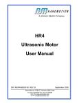
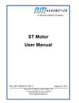
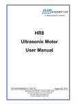
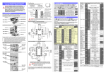
RC3 Ultrasonic Motor User Manual D/N: RC03458000-00 REV: F Nanomotion Ltd. POB 623, Yokneam 20692, Israel Tel: 972-73-2498000 Fax: 972-73-2498099 Web Site: www.nanomotion.com E-mail: [email protected] August 29, 2012 CE Compliance Copyright 2000-2012. This document contains proprietary information of Nanomotion, Ltd. and may not be reproduced in any form without prior written consent from Nanomotion Ltd. Limited Warranty Nanomotion (hereinafter NM) warrants the product (other than software) manufactured by it to be free from defects in material and workmanship for a period of time of one year (except those parts normally considered as consumable/expendable components such as motor conditioning brushes). The warranty commences thirty (30) days from the date of shipment. NM warrants those parts replaced under warranty for a period equal to the remaining warranty coverage of the original part. NM’s sole and exclusive obligation under this warranty provision shall be to repair, or at its sole option exchange defective products or the relevant part or component, but only if : (i) the Purchaser reports the defect to NM in writing and provides a description of the defective product and complete information about the manner of its discovery within ten (10) days of its discovery; (ii) NM has the opportunity to investigate the reported defect and determines that the defect arises from faulty material, parts or workmanship; and (iii) the Purchaser returns the affected product to a location designated by NM. These provisions constitute the exclusive remedy of the Purchaser for product defects or any other claim of liability in connection with the purchase or use of NM products. This warranty policy applies only to NM products purchased directly from NM or from an authorized NM distributor or representative. This warranty shall not apply to (i) products repaired or altered by anyone other than those authorized by NM; (ii) products subjected to negligence, accidents or damage by circumstances beyond NM control; (iii) product subjected to improper operation or maintenance (i.e. operation not in accordance with NM Installation Manuals and/or instructions) or for use other than the original purpose for which the product was designed to be used. The warranty stands only when the motors are used with the NM drivers/ amplifiers. NM shall not in any event have obligations or liabilities to the Purchaser or any other party for loss of profits, loss of use or incidental, increased cost of operation or delays in operation, special or consequential damages, whether based on contract, tort (including negligence), strict liability, or any other theory or form of action, even if NM has been advised of the possibility thereof, arising out of or in connection with the manufacture, sale, delivery, use, repair or performance of the NM products. Without limiting the generality of the preceding sentence, NM shall not be liable to the Purchaser for personal injury or property damages. Nanomotion Ltd. Page 2 of 21 Preface and Warranty Patent Information Nanomotion products are covered under one or more of the following registered or applied for patents. 5,453,653; 5,616,980; 5,714,833; 111597; 5,640,063; 6,247,338; 6,244,076; 6,747,391; 6,661,153; 69838991.3; 6,384,515; 7,119,477; 7,075,211; 69932359.5;1186063; 7,211,929; 69941195.5; 1577961; 4813708; 6,879,085; 6,979,936; 7,439,652; 7061158 ;1800356; 1800356; 1800356; 2007-533057 (pending); 2011-093431 (pending); 7,876,509; 10-2007-7009928 (pending); 200780019448.6 ; 7713361.9 (pending); 12/294,926 (pending); GB2008000004178 (pending); GB2009000003796 (pending); 12/398,216 (pending); GB2446428; 12/517,261 (pending); 08702695.1 (pending); 10-2009-7017629 (pending); 12/524,164 (pending); 12/581,194 (pending) Revision History ECO Revision Release date Details NA NA Aug. 2012 Administrative change – added patent information section in front matter. . Nanomotion Ltd. Page 3 of 21 CE Compliance CE Compliance The Nanomotion’s family of drivers and motors complies to the following directives: Safety : IEC 61010-1:1990 EMC :89/336/EEC 93/68/EEC as amended by 92/31/EEC and Harmonized Standards to which conformity is declared: EN 50081- 2 :1993/EN 55011:1991 Generic Emission Standards Class A for radiated emission and Class B for conducted emission. EN 50082- 2 :1995 Generic Immunity Standard NOTE: Standard Nanomotion motors comply with CE regulations. Although the RC3 motors have the same internal design as the standard motors, they are supplied as components for the vacuum system and therefore, CE conformity in both EMI and Safety must be implemented as part of the UHV system design. Nanomotion Ltd. Page 4 of 21 Preface and Warranty Preface This Installation Manual is designed to help the reader install and operate the RC3 Piezo-ceramic Motor. This manual assumes that the reader has a fundamental understanding of basic servo systems, as well as motion control concepts and applicable safety procedures. The manual describes the physical dimensions as well as the mechanical and electrical installation procedures for these motors. Warranty The motors are covered by warranty for a period of twelve months from the date of invoice. The following voids the warranty: Misuse or incorrect mounting, incorrect electrical connections, removal of motor cover or of serial number, modification of parts, and any other use that is not according to the cautions and warnings provided in this guide. Liability for replacement will be determined after inspection of any defective item by Nanomotion or an approved agent. Nanomotion Ltd. Page 5 of 21 Definition of Terms and Warnings Definition of Terms NOTE: Additional useful information. CAUTION: Identifies conditions or practices that could result in damage to this product or other property. WARNING: Identifies conditions or practices that could result in personal injury, damage to the product or other property. Warnings and Cautions WARNINGS Do not attempt to open the motor. High voltage inside. Be sure to ground the motor to the electrical network ground before operating. CAUTIONS Do not set power-on unless motor is mounted and preloaded! Do not immerse the motor in any liquid or cleaning agent. Use only a clean cloth to wipe the motor. Nanomotion Ltd. Avoid mechanical stress on the flex tail. Be sure that the motor, and specifically the 'finger tips', are not subjected to mechanical shocks. Be sure that the distance of the motor to the plate enables the motor finger tip to contact the driving plate, otherwise the motor might be damaged during operation. The mounting base and the method used for mounting should be designed for maximum mechanical rigidity and stiffness. Page 6 of 21 Table of Contents Table of Contents 1. 2. 3. INTRODUCTION ............................................................................................................8 1.1 About the Motor ..............................................................................................8 1.2 Handling ..........................................................................................................9 1.3 Installation and Servicing...............................................................................9 PREPARATION AND INSTALLATION ........................................................................10 2.1 Overview ........................................................................................................10 2.2 Bonding the Driving Plate to the Stage .......................................................10 2.2.1 Mounting the motor .........................................................................................13 2.2.2 Electrical Connection ......................................................................................13 2.2.3 Motor Grounding .............................................................................................13 2.2.4 Motor Run-In ...................................................................................................14 SPECIFICATIONS .......................................................................................................15 3.1 General ..........................................................................................................15 3.2 Specification Parameters .............................................................................17 3.2.1 Specifications..................................................................................................17 3.2.2 Materials Comprising the Motor ......................................................................18 3.2.3 Performance Envelope ...................................................................................19 3.3 Dimensions Layout .......................................................................................21 Nanomotion Ltd. Page 7 of 21 Introduction 1. Introduction 1.1 About the Motor RC3 motors are high precision ceramic motors. Designed and manufactured by Nanomotion, Ltd., these motors combine unlimited stroke with high resolution, all in a compact package. RC3 motors provide a linear response to the input voltage. The operation of the motor and driver resembles that of a DC-motor driven by a voltage amplifier. The RC3-HV and RC3-UHV motors are constructed of materials that have been selected and designed for high vacuum compatibility. NOTE: The specifications described in this manual apply only to the motor driven by the PD7 driver box. Nanomotion Ltd. Page 8 of 21 Introduction 1.2 Handling CAUTIONS Avoid mechanical stress on the flex tail. Do not set power-on unless the motor is mounted and preloaded! Do not immerse the motor in any liquid or cleaning agent. Use only a clean cloth to wipe the motor. Be sure that the motor, and specifically the 'finger tips', are not subjected to mechanical shocks. 1.3 Installation and Servicing It is recommended to follow the installation instructions in this guide, when mounting and installing the motor. The RC3 motor does not contain any user-serviceable parts. Nanomotion Ltd. Page 9 of 21 Preparation and Installation 2. Preparation and Installation 2.1 Overview The installation procedure consists of the following: Bonding the Ceramic Driving plate to the stage Mounting the motor Grounding the motor Connecting the motor to its driver 2.2 Bonding the Driving Plate to the Stage The Driving Ceramic Plate interfaces between the motor 'finger tips' and the stage, providing the required friction. Bond the driving plate to the stage surface interfacing with the motor 'finger tips', according to the instructions given in this section. Stage Ceramic Driving Plate Figure 1: Bonding the Ceramic Driving Plate Nanomotion Ltd. Page 10 of 21 Preparation and Installation 1. Clean the bonding region on the stage, using a suitable agent such as acetone or methanol. 2. Peel off the self-adhesive tape on the Ceramic driving plate. The self adhesive tape is compatible with high-vacuum applications. 3. Referring to the figure below, position the plate, so that there is a distance of at least 0.5mm between the edges of the ceramic plate and the finger-tips. RC3 Motor 0.5 mm 0.5 mm Ceramic Plate Figure 2: Ceramic Drive Plate Position Nanomotion Ltd. Page 11 of 21 Preparation and Installation 4. Referring to the Figure 3, apply at least two drops of epoxy adhesive (about 2cm apart), to the center of the Ceramic driving plate upper surface. The Epoxy must bond the plate and the stage. Recommended adhesive: Emerson & Cuming ecobond 24 (vacuum compatible). NOTE: Be sure the epoxy contacts the upper surfaces of the plate and the stage carriage, but that no excess glue flows over the Ceramic plate front surface. Stage 2 cm Epoxy Ceramic Plate Figure 3: Securing the Ceramic Driving Plate to the Stage 5. Allow the required time period for curing, according to the Epoxy manufacturer specifications. 6. Mount the motor according to the following section. Nanomotion Ltd. Page 12 of 21 Preparation and Installation 2.2.1 Mounting the motor The motor is inserted into the mounting base hole. Make sure all of the dimensions and tolerances specified in the figure below are met. CERAMIC DRIVE PLATE 21 +0.05 41.7±0.05 (COMPRESSED) SLIDE 39 +1 MOTOR MOUNTING BASE (WITH MOTOR INSERTED) Figure 4: Motor Mounting (dimensions in mm) 2.2.2 Electrical Connection Wire the electrical connections to the flex tail using an AMP connector, model 487951-4. 2.2.3 Motor Grounding The motor’s mounting base should be grounded to the main ground. Nanomotion Ltd. Page 13 of 21 Preparation and Installation 2.2.4 Motor Run-In Be sure to perform motor run-in an ambient environment in order to reduce the wear rate of the system and to prolong its lifetime. The required run-in conditions are as follows: • Velocity - 50 mm/sec. • Duty cycle - 50%. • Duration - 4 hours. General remarks: 1. Be sure to operate the motors using only drivers supplied by Nanomotion and the correct resonance circuit. 2. The procedure should be repeated if the motor is disconnected and reinstalled. 3. Do not perform run-in within a vacuum environment. Nanomotion Ltd. Page 14 of 21 Specifications 3. Specifications 3.1 General These specifications apply to the motor driven by the PD7 Driver Box. The motor features a linear voltage response. The motor and driver can be modeled as a DC-motor with friction driven by a voltage amplifier, as illustrated in the following diagram. . Offset Vin + Kf - + 1/M 1/S Vel Kfv Figure 5: Block Diagram of the Motor and Driver Where: Vin - Command to the driver -10 to +10 [V] Kf - Force constant [N/V] Offset - Starting voltage [V] Kfv - Velocity damping factor (similar to back EMF) [N x sec / m] Nanomotion Ltd. Vel - Motor velocity [m/Sec] M - Moving mass [kg] S - Laplace variable [1/sec] Page 15 of 21 Specifications A block diagram of a typical RC3 Driver/Motor Sub-system is illustrated in Figure 5. A command voltage of ±10V is applied to the driver, which then generates a 40.5Khz sine wave (V motor) whose amplitude is a function of command voltage. The sine wave drives the RC3 motor. Velocity, Force V Motor V Command DRIVER RC3 MOTOR Figure 6: Block Diagram of a typical RC3 Driver/Motor Sub-system Nanomotion Ltd. Page 16 of 21 Specifications 3.2 Specification Parameters 3.2.1 Specifications Performance Maximum Velocity: 180 [mm/sec] (min). Dynamic Stall Force: 12 [N] (min) Force @ 80 mm/sec 8.5 [N] (min) Non-Energized Stiffness 1.8 [N/µ] (min) (less for HV motor) Nominal Preload on Stage 50 [N] Kf 2.7 ±40% [N/Volt command] Kfv 50 ±20% [N • sec/m] Offset 1 to 2 [V] Attainable Resolution Better than 100nm – See application notes Nominal Lifetime 20,000 hours under nominal operating conditions Electrical Maximal Voltage: 280Vrms, 40.5KHz, sine wave Maximal Current consumption: 270mA rms ± 30mA Maximal Power Consumption: 17W ± 2W (zero W at hold) Electrical Connection 4 contact edge connector on FPC Environmental Ambient Temperature: 0 - 50°C Storage: -20°C - +70°C Humidity: 0 - 80% non condensing Vacuum level (ultra-high-vacuum motors): 10 Maximal Baking Temperature 140ºC -10 Torr (guaranteed only after baking) Physical Dimensions Diameter ∅21mm Length 41.7mm Weight 34 gr. Nanomotion Ltd. Page 17 of 21 Specifications 3.2.2 Materials Comprising the Motor AL 2024-T6 Peek Viton Conifer Tellurium Copper Silver coated Tellurium Copper Fired Silver Electrodes PZT Alumina Vacuum Epoxy Kapton – Pyralux Flexible Printed Circuit SS AISI 304 Nanomotion Ltd. Page 18 of 21 Specifications 3.2.3 Performance Envelope The following graph illustrates motor velocity as a function of the applied driver command voltage under no load. Allowing up to 30 mm/sec variations, use it as a reference and as a guideline for expected motor performance, Motors velocity VS command . Velocity [mm/sec] 300.0 250.0 200.0 150.0 100.0 50.0 0.0 0 1 2 3 4 5 6 7 8 9 10 Command [V] Figure 7: Motor Velocity vs. Command 1 1 The motor operates horizontally at room temperature and low duty cycle (< 10%). It interfaces a Ceramic Strip (according to Nanomotion Specifications) and a cross-roller high quality slide. Nanomotion Ltd. Page 19 of 21 Specifications The following graph and table are designed to help the user determine the correct performance envelope of operation so as to not overheat and damage the motor. ForceVs.Velocityatvariousworkregimes 12 Force [N] 10 8 6 g 4 c 2 0 d e f b a 0 100 200 300 Velocity[mm/sec] 25°C Curve Duty Cycle VACUUM 50° C Maximum Continuous Cycle Operation (sec) Duty Cycle Maximum Continuous Cycle Operation (sec) Duty Cycle Maximum Continuous Cycle Operation (sec) a 100% - 100% - 100% - b 100% - 100% - 44% 184 c 100% - 92% 137 26% 107 d 100% - 62% 93 17% 72 e 78% 87 sec. 47% 70 13% 55 f 56% 63 sec. 33% 50 9% 39 g 50% 56 sec. 30% 45 8% 35 Figure 8: Performance Envelope At Various Work Regimes Defining a performance envelope (example of the use of the above graph and table) A vacuum application requires 4N at a velocity of 60mm/sec. The graph shows that this point of operation corresponds to curve “c ”. The table shows that curve “c” and a vacuum environment require that a duty cycle of 26% will not be exeeded while maintaining a maximum continuous operation time of 107 seconds. Vacuum application note – Heat dissipation mechanism is by radiation to the motor case and by conduction through the fingers. Hence, the motor and the ceramic drive strip bases, must both be thermaly designed to dissipate 0.75W each (per motor), with a temperature rise of 15°C maximum. Also, the temperature of all parts in contact with the motor and with the ceramic drive strip, should not exeed 40°C. Nanomotion Ltd. Page 20 of 21 Specifications 3.3 Dimensions Layout Figure 9: Dimensions Layout Nanomotion Ltd. Page 21 of 21